Sign In
Upload
Manuals
Brands
Allied Telesis Manuals
Switch
AT-FS909M
Allied Telesis AT-FS909M Manuals
Manuals and User Guides for Allied Telesis AT-FS909M. We have
1
Allied Telesis AT-FS909M manual available for free PDF download: Installation Manual
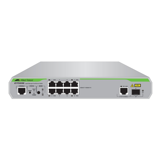
Allied Telesis AT-FS909M Installation Manual (56 pages)
Brand:
Allied Telesis
| Category:
Switch
| Size: 1.66 MB
Table of Contents
Installation Guide
1
Electrical Safety and Emissions Standards
3
Translated Safety Statements
4
Table of Contents
5
Preface
11
Symbol Conventions
12
Contacting Allied Telesis
13
Chapter 1 : Overview
15
Features
16
Twisted-Pair Ports
16
SFP Slots
16
Leds
17
Installation Options
17
MAC Address Table
17
Front and Back Panels
18
Figure 1: AT-FS909M, AT-FS917M, and AT-FS926M Front Panels
18
Figure 2: AT-FS909M, AT-FS917M, and AT-FS926M Back Panels
19
Management Software
20
Twisted-Pair Ports
21
Combo Ports
22
Table 1. Combo Ports
22
Leds
23
STATUS Leds
23
Figure 3: STATUS Leds
23
Table 2. POWER LED Functional Description
23
MODE Leds
24
Figure 4: MODE Leds
24
Table 3. FAULT LED Functional Description
24
Port Leds
25
Figure 5: Port Leds
25
Table 4. MODE LED Functional Descriptions
25
Table 5. Port LED Functional Descriptions
25
SFP Slot Leds
26
Figure 6: SFP Slot Leds
26
Table 6. SFP Slot LED Functional Descriptions
26
Reset Button
27
Mode Button
28
Power Supply
29
Chapter 2 : Installation
31
Reviewing Safety Precautions
32
Selecting a Site for the Switch
35
Cable Specifications
36
Table 7. Twisted-Pair Cabling and Distances
36
Unpacking the Switch
37
Figure 7: Shipping Package Contents
38
Installing the Power Cord Retaining Clip
39
Figure 8: Power Cord Retaining Clip
39
Figure 9: Power Cord Retaining Plates
39
Figure 10: Installing Retaining Plates on the Power Connector
40
Figure 11: Inserting the Retaining Clip into the Retaining Bracket
40
Installing the Switch on a Desktop or Table
41
Installing the Switch in an Equipment Rack
42
Figure 12: Attaching the Rack-Mount Brackets to the Switch
42
Figure 13: Mounting the Switch in an Equipment Rack
42
Installing SFP Transceivers
44
Figure 14: Removing the Dust Plug from an SFP Slot
44
Figure 15: Inserting the SFP
45
Figure 16: Positioning the SFP Handle in the Upright Position
45
Cabling the Switch
47
Powering on the Switch
48
Figure 17: Plugging in the AC Power Cord
48
Chapter 3 : Troubleshooting
51
Appendix A : Technical Specifications
53
Physical Specifications
53
Dimensions
53
Weight
53
Environmental Specifications
53
Table 8. Chassis Dimensions
53
Table 9. Chassis Weight
53
Table 10. Environmental Specifications
53
Power Specifications
54
Safety and Electromagnetic Emissions Certifications
54
Table 11. Power Specifications
54
Table 12. Safety and Electromagnetic Emissions Certifications
54
Connectors and Port Pinouts
55
Figure 18: RJ-45 Connector and Port Pin Layout
55
Table 13. MDI Pin Signals (10Base-T or 100Base-TX)
55
Table 14. MDI-X Pin Signals (10Base-T or 100Base-TX)
55
Advertisement
Advertisement
Related Products
Allied Telesis AT-FS906E
Allied Telesis AT-FS905E
Allied Telesis AT-FS917M
Allied Telesis AT-FS980M/28
Allied Telesis AT-FS980M/28PS
Allied Telesis AT-FS980M/52
Allied Telesis AT-FS980M/9PS
Allied Telesis AT-FS980M/18PS
Allied Telesis AT-FS970M/8
Allied Telesis AT-FS970M/8PS
Allied Telesis Categories
Switch
Network Router
Media Converter
Network Hardware
Wireless Access Point
More Allied Telesis Manuals
Login
Sign In
OR
Sign in with Facebook
Sign in with Google
Upload manual
Upload from disk
Upload from URL