Advertisement
Quick Links
45 Class
2-cycle engine
70 Class
4-cycle engine
Or Electric equivalent
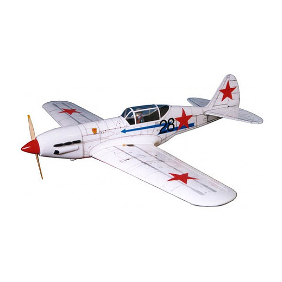
VQA016 (White)
TECHNISCHE DATEN
Spannweiter
Lange
Elektroantrieb
Verbrennerantrieb
Fernsteuerung
WARNING! This radio controlled model is NOT a toy. If modified or flown carelessly it could go out of controll and
cause serious human injury or property damage. Before flying your airplane, ensure the air field is spacious enough.
Always fly it outdoors in safe areas and seek professional advice if you are unexperienced.
ACHTUNG! Dieses ferngesteuerte Modell ist KEIN Spielzeug! Es ist für fortgeschrittene Modellflugpiloten bestimmt,
die ausreichende Erfahrung im Umgang mit derartigen Modellen besitzen Bei unsachgemäßer Verwendung kann
hoher Personen- und/oder Sachschaden entstehen. Fragen Sie in einem Modellbauverein in Ihrer Nähe um
professionelle Unterstützung, wenn Sie Hilfe im Bau und Betrieb benötigen. Der Zusammenbau dieses Modells ist
durch die vielen Abbildungen selbsterklärend und ist für fortgeschrittene, erfahrene Modellbauer bestimmt.
INSTRUCTION MANUAL / Montageanleitung
All balsa, plywood construction and almost ready to fly
1580mm
1180mm
650 Watt
7.5cc 2-T / 11cc 4-T
5 Kanal / 4-5 Servos
MIKOYAN-GOUREVITCH
MIG-3
MIG-3
SPECIFICATIONS
Wingspan
Length
Electric Motor
Glow Engine
Radio
4 Channel / 4-5 Servos
VQA0161 (Summer Camo)
1580mm
1180mm
870 Watt
.46 2-T / .70 4-T
Advertisement

Related Manuals for VQ VQA016


Summary of Contents for VQ VQA016
- Page 1 45 Class MIKOYAN-GOUREVITCH 2-cycle engine MIG-3 70 Class MIG-3 4-cycle engine Or Electric equivalent INSTRUCTION MANUAL / Montageanleitung All balsa, plywood construction and almost ready to fly VQA016 (White) VQA0161 (Summer Camo) SPECIFICATIONS TECHNISCHE DATEN Wingspan 1580mm Spannweiter 1580mm Length 1180mm...
- Page 2 REQUIRED FOR OPERATION (Purchase separately) BENOTIGTE KOMPONENTEN FUR DEN ABFLUG (Nicht enthalten) Extension for aileron 10.5x6 for .40 - 2 cycle engine servo, retract servo. Retract servo x1 11x6 for .46 - 2 cycle engine 12x6 for .60 - 4 cycle engine 12x7 for .70 - 4 cycle engine 13x6 for Electric Motor...
- Page 3 1/8”x19/32”(3x15mm) both up and down position. screw (included with retract) After checking that the retract works smoothly with the VQ-AR04 - 160224 servos, fix the retract on the wing with 3x15mm screws. (option) 1/8”(3mm) Retract pushrod plywood buffer...
- Page 4 4- Servo mount / Servohalterung Retract servo mount (plywood A,B,C) Einziehfahrwerk servohalterung FWU1 Schneiden Sie etwas Folie weg Cut away only FWU2 the covering CENTER FWU2 WING FWU1 SECTION BOTTOM Install the retract servo onto the retract 5- Retract servo / Einziehfahrwerk servo servo mount and secure it in place with four screw (included with radio set).
- Page 5 6- Fixed gear / Landegestange 3x20mm Main landing gear Nylon gear 3x12mm screw strap ..8 3x20mm screw ..16 Gear mount Nylon gear strap 3x20mm screw ..4 Ply gear mount flat Gear mount x 2 Square plastic 3x20mm 3x20mm screw Ply gear mount plate x 2 Square plastic x 2 Wing - bottom view...
- Page 6 9- Air scoop / Olkuhlerattrappe ABS air scoop 15/32 12mm Using the ABS air scoop as a template, trace around the outside edge of the ABS Sticker air-scoop and then remove it. Using a sharp hobby knife, cut away the covering inside the lines.
- Page 7 1-Trial fit the vertical stabilizer in place . Check the alignment of the 12- Vertical stabilizer / Hohenleitwerk vertical stabilizer. When you are satisfied with the alignment, use a pencil to trace around the right and left of the stabilizer where it Apply the epoxy meets the fuselage.
- Page 8 - Using a plywood motor mounting plate as a template, mark the fire wall 15- Electric Motor / Elektromotor where the four holes are to be drilled (1). - Remove the plywood motor mounting plate and drill a 13/64”(5mm) hole through the fire-wall at each of the four marks marked (2).
- Page 9 ! Engine thrust on balk head ! Align the mark on both mounts 16- Engine mount / Motortrager is already adjust at factory with the center mark on the fire wall B=B’ ! Align the engine B’ center with fire wall marked line B’...
- Page 10 19- Fuel tank installation / Tankeinbau To muffler Secure the battery stand in place using CA glue Filler tube Rubber stopper Magnetic battery hatch 3x25mm To engine screw In case of gas engine After confirming the direction . Insert this assembly, clunk end first, into the fuel tank and tighten and screw the fuel tank cap on firmly.
-
Page 11: Servo Installation
21- Servo installation Receiver area NOTE: Place of the servos may be change depend of engine (Four-stoke or two-stroke engine) 22- Linkages / Ruderanlenkung Rudder pushrod Elevator pushrod Bottom view /Ansicht von unten Rudergestange Rudder servo Seitenruderservo Elevator servo Hohenruderservo Throttle servo Drosselservo 3mm set Screw... - Page 12 26- Decor / Aufkleber VQA016 (White) Sticker VQA0161 (Summer Camo) Sticker Note: Cut out the stickers and apply them in the proper area. Do not peel the backing paper off all at once. Peel off one corner of the backing and cut off with scissors. Arrange sticker on model and when satisfied adhere the corner without backing.
Need help?
Do you have a question about the VQA016 and is the answer not in the manual?
Questions and answers