Table of Contents
Advertisement
Quick Links
VQ No: VQA120
Instruction manual / Montageanleitung
SPECIFICATIONS
Wingspan:.........................1540mm (61.4in)
Length:................................1060mm (46 in)
Electric Motor:.....................See next pager
Glow Engine:.................... .46 2-T / .70 4-T
RTF Weight: 3.2Kg / 7.05lbs (Will vary with
Equipment Used).
Radio:....................7-8 Channel / 7-8 Servos
Function: Ailerons-Elevator-Rudder-Throttle
Flaps-Optional Retractable Landing Gear.
WARNING! This radio controlled model is NOT a toy. If modified or flown carelessly it could go out of controll and
cause serious human injury or property damage. Before flying your airplane, ensure the air field is spacious enough.
Always fly it outdoors in safe areas and seek professional advice if you are unexperienced.
ACHTUNG! Dieses ferngesteuerte Modell ist KEIN Spielzeug! Es ist für fortgeschrittene Modellflugpiloten bestimmt,
die ausreichende Erfahrung im Umgang mit derartigen Modellen besitzen. Bei unsachgemässer Verwendung kann
hoher Personen- und/oder Sachschaden entstehen. Fragen Sie in einem Modellbauverein in Ihrer Nähe um
professionelle Unterstätzung, wenn Sie Hilfe im Bau und Betrieb benötigen. Der Zusammenbau dieses Modells ist
durch die vielen Abbildungen selbsterklärend und ist für fortgeschrittene, erfahrene Modellbauer bestimmt.
Radio control model / Flugmodel
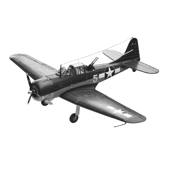
U.S NAVY DIVE BOMBER
ALL BALSA, PLYWOOD CONSTRUCTION AND ALMOST READY TO FLY
TECHNISCHE DATEN
Spannweite:...................................1540mm
Lange:............................................1060mm
Elektroantrieb.............(siehe nächste Seite)
Verbrennerantrieb:...............7.45cc - 11.5cc
Fluggewicht:.......................................3.2Kg
Fernsteuerung..........7-8 Kanal / 7-8 Servos
Advertisement
Table of Contents


Need help?
Do you have a question about the VQA120 and is the answer not in the manual?
Questions and answers