Table of Contents
Advertisement
Quick Links
60 Class
2-cycle engine
90 Class
4-cycle engine
or electric equivalent.
AEROMODELLO RADIOCOMANDATO
RADIO CONTROLED ALMOST READY-TO-FLY ENGINE POWERED ALL BALSA PLANE
.61
cu.in.
.90
cu.in.
WARNING! This radio control model is not a toy. If modified or flow carelessly it could go out of control and cause
serious bodily injury or property damage.
Before flying your airplane, ensure the air field is spacious enough.
Always fly it outdoors in safe areas with no debris or obstacles.
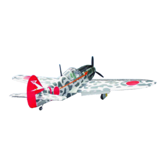
KAWASAKI
Ki-61 Hien "Tony"
INSTRUCTION MANUAL
6 ch.
10V (40A)
Wingspan approx.
Fuselage length approx
6.4 lb.
Kg
(2900g)
VQA048 / VQA049
61.8 in. (1570mm)
48.8 in. (1240mm)
Advertisement
Table of Contents

Related Manuals for VQ KAWASAKI Ki-61 Hien “Tony”


Summary of Contents for VQ KAWASAKI Ki-61 Hien “Tony”
-
Page 1: Instruction Manual
60 Class KAWASAKI 2-cycle engine Ki-61 Hien “Tony” 90 Class 4-cycle engine or electric equivalent. INSTRUCTION MANUAL VQA048 / VQA049 AEROMODELLO RADIOCOMANDATO RADIO CONTROLED ALMOST READY-TO-FLY ENGINE POWERED ALL BALSA PLANE Wingspan approx. 61.8 in. (1570mm) 6 ch. cu.in. Fuselage length approx 48.8 in. - Page 2 REQUIRED FOR OPERATION (Purchase separately) 12x6 for .60 - 4 cycle engine Extension for aileron 13x7 for .90 - 4 cycle engine servo, retract servo. 14X8 for Quantum 4120/07 Phoenix-60 Brushless Motor Control or equivalent. Retract landing gear VQAR010 Retract servo Minimum 6 channel radio for airplane Quantum 4120/07 .60 - 2 cycle...
-
Page 3: Joining The Wing
1-Aileron extension cord installation Aileron servo hatch 30cm Extension cord WING BOTTOM-VIEW Thread Turn the screws and full the aileron and flap servo hatch out of the wing half. Using the thread (pre-installed at factory) to slide the aileron and flap extension cord into the wing half. -
Page 4: Retract Servo
3- Joinning the wing Glue Wing joiner Wing half Glue must go inside ! Make sure to glue securely, If not properly glued, a failure in flight may occur. WING TOP-VIEW 30 min. Epoxy Carefully slide the wing halves together, 30 min. -
Page 5: Fixed Gear
6- Retract and struts 3x15mm viti 3x15mm ..8 ..8 BOTTOM VIEW STEP STEP 5/64” STEP Note: Struts and retract not included. With the retract and retract servo in the retracted position, mark the position 7- Retract linkage where each of the pushrod will attach to the servo arm, a small piece of masking tape works well for this. -
Page 6: Aileron Servo
9- Fixed gear ABS gear cover 3x12mm screw ABS gear cover 2x6mm screw 1.5mm 3x12mm screw ABS gear strap ..8 Gear mount 2x6mm screw BOTTOM VIEW ..4 (plywood) ABS wheel well cover (for fixed gear) 10- Fixed gear BOTTOM VIEW 11- Aileron servo Aileron servo hatch (ply 3mm) - Page 7 12- Aileron and flap linkage Aileron extension cord exit Aileron extension cord Aileron servo hatch Flap servo hatch flap extension cord Flap servo hatch 2x10mm BOTTOM VIEW Servo mount Installing the flap servo on to the hatch (side-view) 1.5mm Pushrod exit hole WING BOTTOM Flap servo Hatch Flap pushrod...
-
Page 8: Vertical / Horizontal Stabilizer
Trial fit each part before gluing . Be certain that there 14- Vertical / Horizontal stabilizer are no gaps. If the parts will join, but with a gaps, sand or trim the parts a little at a time until the parts meet exactly with no gaps. - Page 9 16- Linkages BOTTOM VIEW Connector ...2 Elevator push rod Tail wheel push rod Elevator servo Connector ....3 2mm screw Throttle pushrod Throttle servo Rudder servo Elevator push rod Rudder push rod Throttle / Rudder servo 2mm screw Connector Elevator pushrod Elevator servo 17- Tail gear BOTTOM-VIEW...
-
Page 10: Engine Mount
18- Engine mount ! Align the mark on both mounts with the mark on the fuselage Note: Engine thrust on balk head is already adjust at factory FRONT-VIEW B’ FRONT-VIEW B=B’ 1-Using a pencil or felt tipped pen, mark the fire wall where the four holes are to be drilled. - Page 11 20- Engine installation -Reposition the engine on the mounting beams , aligning it with the holes drilled. Insert one 3x25mm screw through each of the mounting holes. Apply silicon (Blue-Locktile 242) to each of the 3x25mm screw and firmly secure the engine to the engine mount using four 3mm nuts.
-
Page 12: Electric Motor
FUEL TANK INSTALLATION 22- Fuel tank To muffler Filler tube Rubber stopper After confirming the direction . Insert this assembly, clunk end first, into the fuel tank and tighten and screw the fuel tank cap on firmly. Blow Fuel tube Stopper To engine Water... -
Page 13: Machine Guns
Remove the engine and insert the cowl on to the fuselage 25- Cowling so the distance from the fire wall to the front of the cowl is 109 to 111mm (4-21/64”) Remove the cowl from the fuselage and carefully cut the opening for the engine head as marked above. -
Page 14: Air Scoop
27- Air scoop Bottom view Plastic air scoop 6x50mm nylon bolt 6X50mm bolt 12mm 15/32” ...2 Plastic wing cover Using the ABS air scoop as a template, trace around the outside edge of the ABS air-scoop and then remove it. Using a sharp hobby knife, cut away the covering inside the lines. -
Page 15: Control Surface
30- Sticker Sticker Sticker 31- Balance Note: Adjust the location of the battery pack to achieve this C.G location. DO NOT try to fly an out-of balance model! 4 ~ 4-1/8” (100 ~ 105mm) 32- Control surface 15/64”(6mm) 15/64”(6mm) AILERON STROKE 13/32”(10mm) 1-23/64””(35mm) 13/32”(10mm) - Page 16 PRE-FLIGHT CHECKING AND ADJUSTING YOUR MODEL It is almost impossible to fly your model without checking and adjusting your model. You can stop easily if your car is not running strait. But you cannot stop your airplane after take off. Your plane could go right or left. Or even go up or down.
Need help?
Do you have a question about the KAWASAKI Ki-61 Hien “Tony” and is the answer not in the manual?
Questions and answers