Table of Contents
Advertisement
Quick Links
Radio control model / Flugmodel
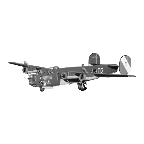
B-24 LIBERATOR
ALMOST READY TO FLY
ALL BALSA AND PLYWOOD CONSTRUCTION
Instruction manual / Montageanleitung
SPECIFICATIONS
Wingspan:......................................2800mm
Length:.........................................17000mm
Electric Motor:.....................See next pager
Glow Engine:...................21-27 2-T / 40 4-T
RTF Weight: 10.5Kg (will vary with equipment
use)
Radio:........................9 Channel / 11 Servos
Function: Ailerons-Elevator-Rudder-Throttle
Flaps-Optional Retractable Landing Gear.
TECHNISCHE DATEN
Spannweite:...................................2800mm
Lange:............................................1700mm
Elektroantrieb.............(siehe nächste Seite)
Verbrennerantrieb:.............21-25 2T / 40 4T
Fluggewicht:......................................10.5Kg
Fernsteuerung................9 Kanal / 11 servos
Advertisement
Table of Contents

Related Manuals for VQ B-24 LIBERATOR


Summary of Contents for VQ B-24 LIBERATOR
- Page 1 Radio control model / Flugmodel B-24 LIBERATOR ALMOST READY TO FLY ALL BALSA AND PLYWOOD CONSTRUCTION Instruction manual / Montageanleitung TECHNISCHE DATEN SPECIFICATIONS Wingspan:........2800mm Spannweite:........2800mm Length:.........17000mm Lange:..........1700mm Electric Motor:.....See next pager Elektroantrieb.....(siehe nächste Seite) Glow Engine:....21-27 2-T / 40 4-T Verbrennerantrieb:.....21-25 2T / 40 4T...
- Page 2 B-24 LIBERATOR HISTORY: The Consolidated B -24 Liberator was designed with the high aspect -ratio Davis Wing. In combat, the wing had drawbacks as far as durability was concerned, but it increased fuel efficiency and gave the B-24 a longer range than the Boeing B -17 Flying Fortress.
- Page 3 RADIO REQUIRED: NORMAL EP - Radio 9 channels with 11 servos - 5 high torque servos ( 2x ailerons + 2x elevator + 1x nose wheel ) - 2 mini 9gr servo for rudder. - 4 mini servo for flaps RADIO REQUIRED: NORMAL GP - Radio 9 channels with 15 servos.
-
Page 4: Motor Mount
B-24 LIBERATOR 1- MOTOR MOUNT Motor mount - Bottom view Paste the B1 and B1A onto the both sides of the B1 Motor mount as show. (Paste the B2 and B2A onto the both sides of the B2 Motor mount) Note: You are need to do step 1A and 1B when using the glow engine. - Page 5 B-24 LIBERATOR 2- MOTOR MOUNT WING - TOP VIEW Note: The arrow to upper. ! Align the mark on both sides of the motor mount with the surface of the wing Step 2A Note: The arrow to upper. Trial fit the motor mounting into the slots on the wing panel.
-
Page 6: Brushless Motor Installation
B-24 LIBERATOR 3- BRUSHLESS MOTOR INSTALLATION B-24 Using a aluminum motor mounting plate Remove the aluminum motor mounting as a template, mark the plywood motor plate and drill a 1/8”(3mm) hole through mounting plate where the four holes are the plywood at each of the four marks to be drilled. -
Page 7: Glow Engine Installation
B-24 LIBERATOR 4- BRUSHLESS MOTOR INSTALLATION 98mm A= 98mm B’ B=B’ Installation other motor with the same way. B-24 LIBERATOR 5- GLOW ENGINE INSTALLATION pic.4a Attach the engine mount beams onto the fire-wall so the distance between of two engine mount beams is “C”, and D=D’ as show (see pic. 4c) Secure the engine mount beams onto the fire-wall with litter CA glue. - Page 8 B-24 LIBERATOR 6- GLOW ENGINE INSTALLATION Carefully remove the engine mount beams and drill a 4mm hole through the fire-wall at each of the four marks made above. Insert the blind-nut with the wooden washer onto each of the four holes make above.
-
Page 9: Fixed Gear Installation
B-24 LIBERATOR 7- FIXED GEAR ASSEMBLY Main gear (left) Main landing gear 3x20mm Main gear (right) Nylon gear strap Ply gear mount flat Plastic strap Gear mount Square plastic Gear mount 3x20mm screw..16 (plywood) 3x20mm Ply gear mount plate Square plastic... - Page 10 B-24 LIBERATOR 9- ERETRACT WITH STRUT INSTALLATION GEAR SWITCH EXTENDED RETRACTED 3x20mm screw...
- Page 11 B-24 LIBERATOR 10- ERETRACT WITH STRUT INSTALLATION Robart Electric retract & Strut ( for VQ B-24) www.VQwarbirds.com 3x10mm screw Note: Screws for the Robart retract installation not include.
- Page 12 B-24 LIBERATOR 11- FUEL TANK MOUNT INSTALLATION Fuel-tank stand B1-1A B1 Engine mount Fuel-tank stand B2-2A B2 Engine mount Note: You are need to do this when using the glow engine. If you use an electric motor, you don’t need to do this.
-
Page 13: Fuel Tank Installation
B-24 LIBERATOR 13- FUEL TANK INSTALLATION Note: Silicon fuel line not include. B-24 LIBERATOR 14- MAIN WHEEL 2x6mm screw... -
Page 14: Servo Installation
B-24 LIBERATOR 15- SERVO INSTALLATION... -
Page 15: Shield Installation
B-24 LIBERATOR 16- SHIELD INSTALLATION Dummy engine 2.5x8mm screw... - Page 16 B-24 LIBERATOR 17- BOMB DOOR ASSEMBLY magnetic piece Note: “T” sheet for the front bomb door “S” sheet for the rear bomb door...
- Page 17 B-24 LIBERATOR 18- TOP-TURRET ASSEMBLY...
- Page 18 B-24 LIBERATOR 19- LOWER BALL-TURRET ASSEMBLY 3x25mm screw (not include) 2x6mm screw...
- Page 19 B-24 LIBERATOR 20- TAIL-TURRET ASSEMBLY 2x6mm screw...
- Page 20 B-24 LIBERATOR 21- NOSE-TURRET ASSEMBLY...
- Page 21 B-24 LIBERATOR 22- NOSE-TURRET ASSEMBLY continued...
-
Page 22: Rudder Servo
B-24 LIBERATOR 23- SERVO INSTALLATION Elevator servo Tail turret servo B-24 LIBERATOR 24- RUDDER SERVO Rudder servo Servo mount Servo mount Rudder servo hatch... - Page 23 B-24 LIBERATOR 25- RUDDER CONTROL HORN & LINKAGE B-24 LIBERATOR 26- ELEVATOR CONTROL HORN HORIZONTAL STABILIZER Bottom-view...
-
Page 24: Rudder Installation
B-24 LIBERATOR 27- RUDDER INSTALLATION HORIZONTAL STABILIZER Top-view 3x15mm bolt... -
Page 25: Vertical & Horizontal Stabilizer
B-24 LIBERATOR 28- VERTICAL & HORIZONTAL STABILIZER 6x50mm nylon bolt Secure the Stabilizer to the fuselage using 6x50mm nylon bolt..1... - Page 26 B-24 LIBERATOR 29- NOSE FIXED GEAR INSTALLATION Secure the nose fixed gear to the fuselage using 3x20mm bolt. Note: You should add more 30 minutes-Epoxy glue to the area in the drawing to reinforcement. 3x20mm bolt ...4...
- Page 27 B-24 LIBERATOR 30- NOSE ERETRACT & STRUT INSTALLATION Secure the nose E-retract gear to the fuselage using 3x20mm screw. 3x20mm bolt ...4...
- Page 28 B-24 LIBERATOR 31- NOSE E-RETRACT & STRUT INSTALLATION Robart E-Retract & Strut www.VQwardbirds.com Secure the nose E-retract gear to the fuselage using 3x20mm screw. To servo To servo 3x20mm bolt ...4...
-
Page 29: Nose Gear Door Installation
B-24 LIBERATOR 32- NOSE GEAR DOOR INSTALLATION 2x6mm screw 2x6mm screw... - Page 30 B-24 LIBERATOR 33- TOP TURRET INSTALLATION 5mm dia. hole Note: Secure the servo arm to the bottom of other turrets do the same way. 2x8mm screw...
- Page 31 B-24 LIBERATOR 34- TAIL TURRET INSTALLATION 2x8mm screw B-24 LIBERATOR 35- HORIZONTAL STABILIZER SHIELD 2x6mm screw 2x6mm screw...
- Page 32 B-24 LIBERATOR 36- TOP TURRET INSTALLATION 2x8mm screw 2x8mm screw...
-
Page 33: Joining The Wing Halves
B-24 LIBERATOR 37- JOINING THE WING HALVES... - Page 34 B-24 LIBERATOR 38- JOINING THE WING HALVES continued...
- Page 35 B-24 LIBERATOR 39- TOP HATCH INSTALLATION...
- Page 36 B-24 LIBERATOR 40- NOSE TURRET INSTALLATION 2x8mm screw...
- Page 37 B-24 LIBERATOR 41- DECOR B-24 LIBERATOR 42- SIDE GUN MOUNT & WINDOW SHIELD Gun mount window shield...
- Page 38 B-24 LIBERATOR 43- SIDE GUN B-24 LIBERATOR 44- BALANCE Note: Adjust the location of the battery pack to achieve this C.G location. (100 ~ 107mm) DO NOT try to fly an out-of balance model! Wing center section B-24 LIBERATOR 45- CONTROL SURFACE...
- Page 39 B-24 LIBERATOR 46- DECAL B-24 Olive B-24 “Witchcraft” Decal sheet 1 B-24 “Witchcraft” Decal sheet 2 Note: Cut out the stickers and apply them in the proper area. Do not peel the backing paper off all at once. Peel off one corner of the backing and cut off with scissors.
- Page 40 B-24 LIBERATOR 47- DECAL B-24 Silver 442052 442052 B-24 “Libby Gals” Decal sheet...
Need help?
Do you have a question about the B-24 LIBERATOR and is the answer not in the manual?
Questions and answers