Advertisement
Quick Links
RADIO CONTROL MODEL / RC FLUGMODELL
46 Class
70 Class
Or Electric equivalent
Instruction manual / Montageanleitung
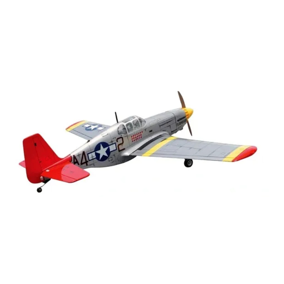
ALL BALSA, PLYWOOD CONSTRUCTION AND ALMOST READY TO FLY
"TUSKEGEE"
Airman
SPECIFICATIONS
Wingspan
Length
Electric Motor
Glow Engine
Radio
4-5 Channel / 4-5 Servos
TECHNISCHE DATEN
Spannweiter
Lange
Elektroantrieb
Verbrennerantrieb
Fernsteuerung
4-5 Kanal / 4-5 Servos
WARNING! This radio controlled model is NOT a toy. If modified or flown carelessly it could go out of controll and
cause serious human injury or property damage. Before flying your airplane, ensure the air field is spacious enough.
Always fly it outdoors in safe areas and seek professional advice if you are unexperienced.
ACHTUNG! Dieses ferngesteuerte Modell ist KEIN Spielzeug! Es ist für fortgeschrittene Modellflugpiloten bestimmt,
die ausreichende Erfahrung im Umgang mit derartigen Modellen besitzen Bei unsachgemäßer Verwendung kann
hoher Personen- und/oder Sachschaden entstehen. Fragen Sie in einem Modellbauverein in Ihrer Nähe um
professionelle Unterstützung, wenn Sie Hilfe im Bau und Betrieb benötigen. Der Zusammenbau dieses Modells ist
durch die vielen Abbildungen selbsterklärend und ist für fortgeschrittene, erfahrene Modellbauer bestimmt.
(2T Engine)
(4T Engine)
1580mm
1180mm
870 Watt
.46 2-T / .70 4-T
1580mm
1180mm
870 Watt
7.5cc 2-T / 11cc 4-T
NORTH AMERICAN
VQA05 "Tuskegee"
VQA06 "Shangri-la"
474976
Advertisement

Related Manuals for VQ VQA05 Tuskegee


Summary of Contents for VQ VQA05 Tuskegee
- Page 1 RADIO CONTROL MODEL / RC FLUGMODELL NORTH AMERICAN 46 Class (2T Engine) 70 Class (4T Engine) Or Electric equivalent Instruction manual / Montageanleitung ALL BALSA, PLYWOOD CONSTRUCTION AND ALMOST READY TO FLY “TUSKEGEE” Airman VQA05 “Tuskegee” 474976 VQA06 “Shangri-la” SPECIFICATIONS Wingspan 1580mm Length...
- Page 2 REQUIRED FOR OPERATION (Purchase separately) BENOTIGTE KOMPONENTEN FUR DEN ABFLUG (Nicht enthalten) Extension for aileron, retract servo and 10.5x6 for .40 - 2 cycle engine Retract servo x1 receiver battery pack. 11x6 for .46 - 2 cycle engine 12x6 for .60 - 4 cycle engine 12x7 for .70 - 4 cycle engine...
- Page 3 LANDING GEAR gear arm and trial fit the retract into the wing. 3x20mm screw Retract push rod Retract gear arm (not included) Put the nylon ring VQ-AR03 -160223 Retract (option) Plywood buffer Retract pushrod included with Fahrwerkanlenkgestange retract set. Bottom view /Ansicht von unten After checking that the retract works smoothly, fix the retract on the wing with 3x20mm self tapping screws.
-
Page 4: Retract Servo Installation
Fahrwerk servohalterung 3- Servo tray / Servohalterung Retract servo tray Retract servo mount Retract servo CENTER mount WING SECTION BOTTOM Retract servo tray installation Cut away only the covering Schneiden Sie etwas Folie weg 4- Servo Installation Install the retract servo onto the retract servo mount and secure it in place with four screw (included with radio set). - Page 5 6- Electric retract landing gear / Einziehfahrwerk ELECTRIC RETRACT LANDING GEAR EXTENDED POSITION RETRACTED POSITION ELECTRIC RETRACT LANDING GEAR GEAR RECEIVER Bottom view /Ansicht von unten 7- Fixed gear / Starres Fahrwerk 3x20mm Main landing gear 3x12mm screw Nylon gear strap ..8 3x20mm screw...
- Page 6 10- Fixed gear / Starres Fahrwerk 2x6mm screw ..4 4mm collar ...2 ..2 10- Wing bolt flat / Verstarkung Wing bolt flat 1/8”(3mm)plywood Wing bolt flat Cut away only the covering Bottom view /Ansicht von unten Center line Using the wing bolt flat as a Wing bolt flat template, trace around the outside edge of the wing bolt flat and then remove it.
-
Page 7: Aileron Servo Installation
12- Aileron extension cord Aileron extension cord exit hole To one end of the aileron extension cord Keep the aileron extension cord in place using sticker. 13- Aileron servo installation Control horn ....2 2x15mm screw ..4 Bottom view /Ansicht von unten 14- Linkage Connector ..2... - Page 8 Bottom view /Ansicht von unten 15- Air Scoop/wing cover / Olkuhlerattrappe 6x40mm nylon bolt 15/32” ..2 Plastic air scoop 12mm Wing cover Wing bolt plat 1/8”(3mm) ply Cut away the covering inside the line before install the air scoop and wing cover 1-Using the ABS air scoop as a template, trace around the outside edge of the ABS air-scoop,and then remove it.
- Page 9 5/32x1” 1/8x5-1/64” 18- Engine mount - engine / Motoreinbau 4x25mm screw 3x20mm screw ...4 ...4 Blind-nut 1/8”(3mm) nut ....4 ....4 ! Align the mark on both mounts with the mark on the fuselage ! Engine thrust on balk head is already adjust at factory B’...
- Page 10 19- Fuel tank / Tankeinbau Blow To muffler Water Filler tube Rubber stopper 3x25mm screw To engine 3x35 mm screw After confirming the direction . Insert this assembly, clunk end first, into the fuel Checking for leaks - block the vents and blow tank and tighten and screw the fuel tank cap on firmly.
- Page 11 Securely glue together. If coming off during 21- Horizontal stabilizer / Hohenleitwerk flight, you lose control of your air plane. Cut away only the covering both Vergewissern Sie sich, sauber geklebt the right and left side zu haben. Andernfalls konnen Probleme mit der Flugeigenschaft auftreten! B’...
- Page 12 23- Elevator installation / Hohenruder Securely glue together. If coming off during flight, you lose control of your air plane. Vergewissern Sie sich, sauber geklebt zu haben. Andernfalls konnen Probleme mit der Flugeigenschaft auftreten! 3/8 in. (9.5mm) Apply a thin layer of machine oil or petroleum jelly to only the pivot point of the hinges on the elevator, then push the elevator and its hinges into the hinge slots in the trailing edge of the horizontal stabilizer.
-
Page 13: Bottom View
Bottom view /Ansicht von unten 25- Radio and battery / Fernsteuerung u .Akku Tail wheel push rod Rudder push rod Battery area (in case of 2T engine) 4-49/64” (120mm) 2-61/64” (75mm) Battery area (in case of 4T engine) Elevator push rod Throttle push rod 800-1000mah, flat pack Hatch... - Page 14 1/16” 3/32x25/64” self tapping screw 27- Cowling installation / Motorhaube 1~2mm 2.5x10mm ....4 1-Attach the board or transparent plastic on the side of the fuselage Adhesive Board or with the adhesive tape as show. tape transparent 2-Using a pencil or felt tipped pen trace around the engine head where plastic it meet the cowl.
- Page 15 30- Decor / Aufkleber Sticker Note: Cut out the stickers and apply them in the proper area. Do not peel the backing paper off all at once. Peel off one corner of the backing and cut off with scissors. Arrange sticker on model and when satisfied adhere the corner without backing.
Need help?
Do you have a question about the VQA05 Tuskegee and is the answer not in the manual?
Questions and answers