Table of Contents
Advertisement
Quick Links
Download this manual
See also:
Instruction Manual
Radio control model / RC Flugmodel
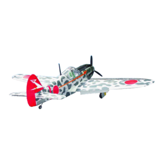
KAWASAKI
Ki-61 Hien "Tony"
INSTRUCTION MANUAL / MONTAGEANLEITUNG
SPECIFICATIONS
Wingspan
Length
Electric Motor
870 Watt (PULSAR 60)
Glow Engine
Radio
5 Channel / 5 Servos
TECHNISCHE DATEN
Spannweiter
Lange
Elektroantrieb
870 Watt (PULSAR 60)
Verbrennerantrieb
Fernsteuerung
WARNING! This radio controlled model is NOT a toy. If modified or flown carelessly it could go out of controll and
cause serious human injury or property damage. Before flying your airplane, ensure the air field is spacious enough.
Always fly it outdoors in safe areas and seek professional advice if you are unexperienced.
ACHTUNG! Dieses ferngesteuerte Modell ist KEIN Spielzeug! Es ist für fortgeschrittene Modellflugpiloten bestimmt,
die ausreichende Erfahrung im Umgang mit derartigen Modellen besitzen Bei unsachgemäßer Verwendung kann
hoher Personen- und/oder Sachschaden entstehen. Fragen Sie in einem Modellbauverein in Ihrer Nähe um
professionelle Unterstützung, wenn Sie Hilfe im Bau und Betrieb benötigen. Der Zusammenbau dieses Modells ist
durch die vielen Abbildungen selbsterklärend und ist für fortgeschrittene, erfahrene Modellbauer bestimmt.
1580mm
1180mm
7.5cc 2T / 8.5cc 4T
1580mm
1180mm
7.5cc 2T / 8.5cc 4T
5 Kanal / 5 Servos
Advertisement
Table of Contents

Related Manuals for VQ KAWASAKI Ki-61 Hien “Tony”


Summary of Contents for VQ KAWASAKI Ki-61 Hien “Tony”
- Page 1 Radio control model / RC Flugmodel KAWASAKI Ki-61 Hien “Tony” INSTRUCTION MANUAL / MONTAGEANLEITUNG SPECIFICATIONS Wingspan 1580mm Length 1180mm Electric Motor 870 Watt (PULSAR 60) Glow Engine 7.5cc 2T / 8.5cc 4T Radio 5 Channel / 5 Servos TECHNISCHE DATEN Spannweiter 1580mm Lange...
- Page 2 REQUIRED ITEMS / Zum Betrieb wird benotigt 10.5x6 for .40 - 2 cycle engine Extension for aileron 11x6 for .46 - 2 cycle engine servo, retract servo. 12x6 for .60 - 4 cycle engine 12x7 for .70 - 4 cycle engine 13x6 for Quantum 4120/05 60A Brushless ESC 60A Brushless Regler...
-
Page 3: Joining The Wing
1-Aileron extension cord installation 30cm Extension cord Thread (pre-installed at factory) WING BOTTOM-VIEW Using the thread (pre-installed at factory) to slide the aileron extension cord into the wing half. Using the adhesive tape to secure the one end of the aileron extension cord in place. - Page 4 WING TOP-VIEW keep the colour of your model not fade. 4- Retract landing gear Steel clevis ..2 1/8”x19/32”(3x15mm) screw (included with VQ-AR04 - 160224 retract) (option) 1/8”(3mm) plywood buffer (included with retract) 1-Join the push rod to the retract gear arm and trial fit the retract into the wing.
- Page 5 5- Retract servo mount Retract servo tray CENTER WING Note: SECTION Retract servo mount “B”is longer than “C” Retract servo mount BOTTOM Note: The head of servo should be positioned toward the rear of the wing. Cut away only the film CENTER WING TOP-VIEW...
-
Page 6: Fixed Gear
8- Fixed gear Main gear (left) 3x10mm Plastic strap Gear mount Main gear (right) (plywood) Ply gear mount plate Plastic strap Square plastic Gear mount Main landing gear 3x10mm screw..16 3x10mm Gear mount (plywood) Square plastic Ply gear mount plate 9- Fixed gear ABS wheel well cover (for fix gear) Bottom view /... -
Page 7: Aileron Linkage
11- Aileron linkage 2mm screw Aileron pushrod Linkage stopper ..2 Trial fit each part before gluing . Be certain that there are 12- Stabilizer no gaps. If the parts will join, but with a gaps, sand or trim the parts Cut away only the a little at a time until the parts meet exactly with no gaps. -
Page 8: Tail Wheel
Anlenkungsgestange Elevator push rod / Connector ....3 Tail wheel push rod / Anlenkungsgestange 2mm screw Elevator servo Hohenruderservo Rudder servo Seitenruderservo Throttle Throttle servo pushrod Drosselservo Elevator push rod / Anlenkungsgestange Rudder push rod / Anlenkungsgestange Rudder servo Throttle servo Drosselservo Seitenruderservo / Throttle servo... -
Page 9: Engine Mount
15- Engine mount 4x25mm screw ..4 ! Align the mark on both mounts Blind-nut with the mark on the fuselage ....4 ! Engine thrust on balk head is already adjust at factory FRONT-VIEW B’ FRONT-VIEW B=B’ 16- Fuel tank Blow Water To muffler Checking for leaks - block the... -
Page 10: Machine Gun
17- Cowling 1~2mm 2.5x10mm..5 Attach the board or transparent plastic on the side of the fuselage with the adhesive tape as show. Using a pencil or felt tipped pen trace around the engine Adhesive head where it meet the cowl. Cut the opening the board tape Board or transparent plastic for the engine head as marked... -
Page 11: Electric Motor
Using a aluminum motor mounting plate as 19- Electric Motor a template, mark the plywood motor mounting plate where the four holes are to be drilled (2). Remove the aluminum motor mounting plate and drill a 1/8”(3mm) hole through the plywood at each of the four marks marked . -
Page 12: Control Surface
22- Machine gun 9.25”(235mm) ..2 23- Sticker ..2 Sticker (For VQA047 version only) 24- Balance Der Schwerpunkt sollte zwischen 88 mm und 92 mm hinter der Nasenleiste liegen. Für die ersten Flüge empfiehlt es sich, den Schwerpunkt an den vorderen 3.4~ 3.6”...
Need help?
Do you have a question about the KAWASAKI Ki-61 Hien “Tony” and is the answer not in the manual?
Questions and answers