Faraday MPC-6000 Programming Manual
Fire alarm system control unit
Hide thumbs
Also See for MPC-6000:
- Installation, operation and maintenance manual (108 pages) ,
- Programming manual (56 pages) ,
- Installation instructions (2 pages)

Related Manuals for Faraday MPC-6000


Summary of Contents for Faraday MPC-6000
- Page 1 MPC-6000 / MPC-7000 Fire Alarm System Control Unit Programming Manual FARADAY 8 Fernwood Road Florham Park, New Jersey 07932 P/N 315-049403FA-1...
-
Page 3: Table Of Contents
Table Of Contents Introduction..........................1 The Access levels ........................1 User Level ......................1 Maintenance Level....................2 Technician Level.....................2 The Operator Interface ......................3 Interface for User and Maintenance Levels ............3 Interface for the Technician Level................4 Entering Alphanumeric Characters .................5 QUICK START........................6 Automatic programming of a new system...............6 Manual programming of a system ................7 Programming Concepts...................... - Page 4 Setting the Date Format..................19 Clearing the History ....................20 Printing the History ....................20 Printing the Sensitivity Levels ................20 Editing the System Label ..................20 Editing the Device Labels ..................20 Starting Quick Test ....................21 Configuring NAC sound time for Quick Test ............21 Configuring the printer during Quick Test .............21 Programming a Device ..................21 Technician Level ........................
-
Page 5: Introduction
M P C 6 0 0 0 / 7 0 0 0 P R O G R A M M I N G M A N U A L Introduction The MPC 6000/7000 Fire Alarm Control Panels are completely field programmable. Although programming requires no special software skills, a thorough working knowledge of Fire Alarm Control Panels and devices is assumed. -
Page 6: Maintenance Level
M P C 6 0 0 0 / 7 0 0 0 P R O G R A M M I N G M A N U A L Maintenance Level The Maintenance level is accessed via the User Menu and the correct password. The functions accessible in the maintenance level are as follows: •... -
Page 7: The Operator Interface
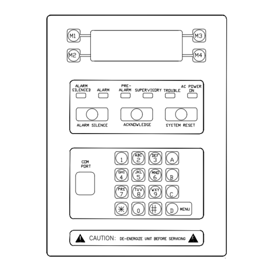
M P C 6 0 0 0 / 7 0 0 0 P R O G R A M M I N G M A N U A L The Operator Interface Interface for User and Maintenance Levels The operator interface for configuring and programming the MPC 6000/7000 uses the 4 line by 20 character LCD display, the M1 through M4 buttons on the left and right of the display and sixteen push buttons at the bottom of the interface. -
Page 8: Interface For The Technician Level
M P C 6 0 0 0 / 7 0 0 0 P R O G R A M M I N G M A N U A L Interface for the Technician Level When the Technician Level is accessed using the password, the LCD display and the keypad are used to program the panel, and to view the programming if desired. -
Page 9: Entering Alphanumeric Characters
M P C 6 0 0 0 / 7 0 0 0 P R O G R A M M I N G M A N U A L Entering Alphanumeric Characters Entry of alphanumeric data using the keypad is as follows: •... -
Page 10: Quick Start
M P C 6 0 0 0 / 7 0 0 0 P R O G R A M M I N G M A N U A L QUICK START Automatic programming of a new system This is the quickest way to get a system operational. After all of the devices, notification appliances and option modules have been programmed and installed, check all wiring for grounds, shorts and opens. -
Page 11: Manual Programming Of A System
M P C 6 0 0 0 / 7 0 0 0 P R O G R A M M I N G M A N U A L Note NOTE #1: The backup configuration will now contain a configuration as follows: all input points in group #241 (General Alarm). - Page 12 M P C 6 0 0 0 / 7 0 0 0 P R O G R A M M I N G M A N U A L Notifications Configure the behavior of the NACs and the appliance circuits output zone that will activate each NAC.
-
Page 13: Programming Concepts
M P C 6 0 0 0 / 7 0 0 0 P R O G R A M M I N G M A N U A L Programming Concepts Program Memory The program memory consists of two components, the PRIMARY (active) configuration and the BACKUP (editable) configuration. -
Page 14: The Programming Model Of The System
P R O G R A M M I N G M A N U A L The programming model of the system The following diagram shows the programming model of the MPC-6000 and MPC-7000 systems. Input devices An input group can... -
Page 15: Automatic Programming
M P C 6 0 0 0 / 7 0 0 0 P R O G R A M M I N G M A N U A L The basic concept is that loop devices are configured and grouped into input groups. The input groups are set to have a certain behavior and activate output zones. - Page 16 Will be set to silenceable. Output Zone Will be set to 1. System Parameter Parameter Description Label Set to “FARADAY AUTO Prgrmd” Drill Enable Auto Silence Timer Alarm Silence Inhibit Panel Reset Inhibit Auto Alarm silence Trouble Reminder 12 hours...
- Page 17 M P C 6 0 0 0 / 7 0 0 0 P R O G R A M M I N G M A N U A L Not included in auto-program The following devices cannot be detected automatically: •...
-
Page 18: User Level
M P C 6 0 0 0 / 7 0 0 0 P R O G R A M M I N G M A N U A L User Level Pressing the menu button displays the User level functions. The user menu allows the operator to activate General Alarm, Alert, Drill, Recall or Lamp Test. -
Page 19: Activating A Recall
M P C 6 0 0 0 / 7 0 0 0 P R O G R A M M I N G M A N U A L Activating a Recall It is possible to sound a Recall from the keypad using the following steps: Press “Menu”, then Press “Recall”. -
Page 20: Accessing Technician Functions
M P C 6 0 0 0 / 7 0 0 0 P R O G R A M M I N G M A N U A L Accessing Technician Functions There are other functions available after the technician password has been entered. Follow the steps below to access the technician functions: Press “Menu”... -
Page 21: Maintenance Level
M P C 6 0 0 0 / 7 0 0 0 P R O G R A M M I N G M A N U A L Maintenance Level Following are the details of the Maintenance level functions. Enabling/Disabling Devices The disable / enable screens allow the operator to disable or enable devices and components of the system. -
Page 22: Enabling/Disabling Nacs
M P C 6 0 0 0 / 7 0 0 0 P R O G R A M M I N G M A N U A L Enabling/Disabling NACs The Notification Appliance Circuits may be disabled/enabled as follows: Press Press “Outputs”. -
Page 23: Changing The Maintenance Password
M P C 6 0 0 0 / 7 0 0 0 P R O G R A M M I N G M A N U A L Changing the Maintenance Password The password for access to the Maintenance level menus may be changed as follows from the Maintenance starting screen: Press “More”... -
Page 24: Clearing The History
M P C 6 0 0 0 / 7 0 0 0 P R O G R A M M I N G M A N U A L Clearing the History The panel can store the last 2000 events in the event history. The information displayed includes the date and time, the type of event (TRB, ALM, SUP, etc.), the device reporting the event and the event reported. -
Page 25: Starting Quick Test
M P C 6 0 0 0 / 7 0 0 0 P R O G R A M M I N G M A N U A L Starting Quick Test The Quick Test mode allows quick and easy testing of the installation. It will allow the devices to be activated and the NACs to sound for a short period of time. -
Page 26: Technician Level
M A N U A L Technician Level The technician level allows complete programming of the MPC-6000/MPC-7000. See the User level functions for the method to access the Technician level. The steps below assume that the technician level has been accessed and that the panel is displaying the starting screen of the technician level. - Page 27 M P C 6 0 0 0 / 7 0 0 0 P R O G R A M M I N G M A N U A L Below are the different parameters that may be set for each of the different devices: Loop Devices FireSmart Thermal...
-
Page 28: Editing An Input Group Configuration
M P C 6 0 0 0 / 7 0 0 0 P R O G R A M M I N G M A N U A L Alarm This usage is selected for fire alarm causing devices. Waterflow Selection for devices connected to Waterflow sensors in sprinkler systems. -
Page 29: Editing A System Group Configuration
M P C 6 0 0 0 / 7 0 0 0 P R O G R A M M I N G M A N U A L investigation phase. If the signal is not acknowledged within 15 seconds a general alarm will sound. The investigation phase can last up to 180 seconds. -
Page 30: Configuring The Remote Relays (Srus)
M P C 6 0 0 0 / 7 0 0 0 P R O G R A M M I N G M A N U A L The parameters that may be set for the NACs are shown in the following table. Parameter Description Notification device type... -
Page 31: Configuring The Remote Lcds (Rdcs)
M P C 6 0 0 0 / 7 0 0 0 P R O G R A M M I N G M A N U A L Configuring the Remote LCDs (RDCs) Following are the steps that need to be followed to configure the remote LCD units. Select Select Use “Cmor”... -
Page 32: Configuring The City Tie Activation
M P C 6 0 0 0 / 7 0 0 0 P R O G R A M M I N G M A N U A L Below is a list of the timers and their functions: Parameter Description Alarm Silence Inhibit The period of time that the alarm will sound before it can be... -
Page 33: Printing The Primary/Backup Configuration
M P C 6 0 0 0 / 7 0 0 0 P R O G R A M M I N G M A N U A L Printing the Primary/Backup Configuration The primary/backup configurations may be printed via the printer port on the panel. Select Select Select “Print... -
Page 34: Exiting The Technician Level
M P C 6 0 0 0 / 7 0 0 0 P R O G R A M M I N G M A N U A L Exiting the Technician Level Follow the steps below to exit the Technician level and return to User level: The Display will return to “Cmor”... -
Page 35: Appendix A: Glossary
M P C 6 0 0 0 / 7 0 0 0 P R O G R A M M I N G M A N U A L APPENDIX A: GLOSSARY Alarm Signal. A signal indicating an emergency requiring immediate action, such as an alarm for fire from a manual station, a waterflow alarm, an automatic smoke detector, etc. - Page 36 Initiating Device Circuit (IDC). A circuit to which initiating devices are connected. Also called a detection loop. A detection loop in the case of the MPC-6000 and MPC-7000 may contain up to 252 detectors or devices, all of which may have outputs.
- Page 37 M P C 6 0 0 0 / 7 0 0 0 P R O G R A M M I N G M A N U A L Output Zone. There may be 255 output zones. Normally used to specify an area of the building for signaling.
-
Page 38: Appendix B: References
APPENDIX B: REFERENCES • • NFPA 72: National Fire Alarm Code (National Fire Protection Association) • NFPA 70: National Electrical Code (Delmar Publishers) • MPC-6000 Faraday Fire Alarm Control Panel Owner's Manual, manual P/N 315- 447309-1 • Faraday web site: http://www.faradayfirealarms.com... - Page 40 FARADAY 8 Fernwood Road Florham Park, New Jersey 07932 P/N 315-049403FA-1...
Need help?
Do you have a question about the MPC-6000 and is the answer not in the manual?
Questions and answers