Faraday MPC-6000 Installation, Operation And Maintenance Manual
Fire alarm system control unit
Hide thumbs
Also See for MPC-6000:
- Installation, operation and maintenance manual (108 pages) ,
- Programming manual (56 pages) ,
- Installation instructions (2 pages)
Table of Contents
Advertisement
Advertisement
Table of Contents

Subscribe to Our Youtube Channel
Related Manuals for Faraday MPC-6000


Summary of Contents for Faraday MPC-6000
- Page 1 MPC-6000 / MPC-7000 / RND-2 Fire Alarm System Control Unit Installation, Operation and Maintenance Manual Siemens Building Technologies, Inc. 8 Fernwood Road • Florham Park, NJ 07932 Tel: (973) 593-2600 • Fax: (973) 593-6670 Web: www.faradayfirealarms.com P/N 315-447309-5...
-
Page 3: Table Of Contents
Serial Interface Circuit ................................9 Status Relays..................................9 Programming Port................................9 OPTIONAL MODULES ..............................10 CT-1K City Tie Board (MPC-6000 / MPC-7000 / RND-2) ....................10 MPC-DACT DACT Board (MPC-6000 / MPC-7000 / RND-2) ..................10 NPE-1 Transformer Assembly (MPC-6000 / MPC-7000) ....................10 NEM-1 NAC Expansion Board (MPC-7000)........................10 LEM-1 Loop Expander Board (MPC-7000) ........................10... - Page 4 Authorized Personnel Only ..............................25 Trouble Operation ................................25 Normal Standby Condition ..............................25 CONTROL UNIT INSTALLATION .......................... 26 PARTS SUPPLIED – MPC-6000 / MPC-7000 / RND-2 .....................26 Enclosure Packages (Black or Red)...........................26 Electronics Package MPC-6000 / MPC-7000 ........................26 Electronics Package RND-2 ..............................26 With NPE-1 Transformer Package ............................26...
- Page 5 Wiring Separation................................38 Primary And Secondary Power Wiring ..........................39 Status Relays And Auxiliary Power Outputs Wiring......................39 MPC-6000 System Power Requirements (Does not include NAC power) .................40 RND-2 System Power Requirements..........................40 MPC-7000 System Power Requirement (Does not include NAC power)................40 Auxiliary Power Supply ..............................41 Battery Size Calculations..............................41...
- Page 6 DEVICES FOR NOTIFICATION APPLIANCE CIRCUITS ....................58 Notification Appliances..............................58 Accessory Devices................................61 DEVICES FOR AUXILIARY POWER OUTPUTS ......................61 Door Holders ..................................61 Relays....................................61 APPENDIX-C: TROUBLESHOOTING........................62 DEFINITIONS FOR EVENT HISTORY ENTRIES ......................62 A. General..................................62 B. System Troubles................................63 C. System Events ................................64 APPENDIX-D: MODULE INSTALLATION INSTRUCTIONS LIST ................ 65 APPENDIX-E: GLOSSARY ............................
-
Page 7: Introduction
MPC-6000 / MPC-7000 / RND-2 INSTALLATION, OPERATION AND MAINTENANCE MANUAL INTRODUCTION CONTROL UNIT LIMITATIONS This control unit may not show an alarm condition without compatible initiating devices (smoke detectors, etc.) and notification devices (horn, lights, etc.) connected to it. Electrical ratings of the initiation and notification appliances must be compatible with the electrical ratings of the control unit and must be properly interconnected. -
Page 8: Installation And Warranty Information
MPC-6000 / MPC-7000 / RND-2 INSTALLATION, OPERATION AND MAINTENANCE MANUAL INSTALLATION AND WARRANTY INFORMATION Warranty Information: Faraday (the Manufacturer) provides a limited warranty to the original purchaser of this product. The original purchaser is the party to whom the manufacturer issued its sales order, generally the manufacturer's distribution. -
Page 9: Preface
MPC-6000 / MPC-7000 / RND-2 INSTALLATION, OPERATION AND MAINTENANCE MANUAL PREFACE Along with the use of this instruction manual, the appropriate following standards and the manufacturer's instructions for initiating and notification devices should be used to install and maintain a functioning fire alarm signaling system. -
Page 10: Descriptions
The MPC-6000 control unit mounts in a 22" x 18" backbox with overall cover size of 22-9/32" x 18-3/8". Operating controls and indicators are mounted on the inside hinged plate. An 80 (4x20) –... -
Page 11: Notification Appliance Circuits
There is also a system coder capable of zone-coded operation. All of the NACs are power limited. Serial Interface Circuit The MPC-6000 control unit has a Serial Interface Circuit that will drive up to 16 remote LCD annunciators and 8 Serial Relay Units and Serial Annunciator Units. Status Relays Four relays with dry contacts are provided. -
Page 12: Mpc-7000 System Description
MPC-6000 / MPC-7000 / RND-2 INSTALLATION, OPERATION AND MAINTENANCE MANUAL MPC-7000 SYSTEM DESCRIPTION The MPC-7000 is an expandable modular fire alarm control unit. It features advanced addressable detection, programming, and memory capability. Its base configuration includes a power supply, two X1 addressable device circuits, four/two notification circuits (NAC), serial interface circuit, four status relays and a programming port. -
Page 13: Notification Appliance Circuits
This reduces the number of NACs to two (six). Each circuit can be selected to give continuous output or one of eight sounding patterns available in the control unit including the Faraday SYNC Protocol. There is also a system coder capable of zone-coded operation. All of the NACs are power limited. -
Page 14: Rnd-2 System Description
MPC-6000 / MPC-7000 / RND-2 INSTALLATION, OPERATION AND MAINTENANCE MANUAL RND-2 SYSTEM DESCRIPTION The RND-2 is a Remote Network Display designed to connect to a Faraday MPC-NET2 Network. It features advanced programming, and memory capability. Its base configuration includes a power supply, serial interface circuit, four status relays and a programming port. -
Page 15: Serial Interface Circuit
MPC-6000 / MPC-7000 / RND-2 INSTALLATION, OPERATION AND MAINTENANCE MANUAL Serial Interface Circuit The RND-2 control unit has a Serial Interface Circuit that will drive up to 16 remote LCD annunciators and 8 Serial Relay Units and Serial Annunciator Units. -
Page 16: Optional Modules
100AH lead acid batteries. Battery Sets The MPC-6000 / MPC-7000 / RND-2 control units are designed to use only sealed lead-acid or equivalent batteries for back-up power. Attaching a close-coupled battery box, if required, may allow use of battery sets beyond the physical capacity of the enclosure (12AH for the MPC- 6000 and 18AH for the MPC-7000). -
Page 17: Auxiliary Modules
The RSE-300 can be configured so that the inputs can be programmed to provide steady outputs, ANSI temporal outputs, or Faraday SYNC protocol for synchronized horn/strobe outputs. It can also be programmed to silence Faraday sync horns while the sync strobes remain on, using two wires. This requires a silenceable and non-silenceable input. -
Page 18: X1 Addressable Devices
• 8720 Device Programmer/ Loop Tester - Refer to the 8720 User’s Manual, P/N 315- 033260FA, for further information. • MPC-6000 / MPC-7000 / RND-2 Panel Keypad – Refer to the MPC-6000 / MPC-7000 / RND-2 Programmer’s Manual, P/N 315-049403FA, for detailed information of system... -
Page 19: Event History
MPC-6000 / MPC-7000 / RND-2 INSTALLATION, OPERATION AND MAINTENANCE MANUAL EVENT HISTORY The control unit includes a non-volatile memory recording up to 2000 system events. Identified alarm, trouble, supervisory trouble and other significant events will be recorded along with the date and time of occurrence and can be inspected by operating front panel push buttons. -
Page 20: General Design Features
MPC-6000 / MPC-7000 / RND-2 INSTALLATION, OPERATION AND MAINTENANCE MANUAL GENERAL DESIGN FEATURES Environmental All hardware is suitable for use in a dry, interior or protected location. Power Limiting The AC power and battery wiring are not power limited. All other circuits leaving the control unit are power limited, provided the proper installation rules are maintained. -
Page 21: Regulatory Standards
Code of Federal Regulations (CFR 47), Part 68, for connection of equipment to the public switched telephone network. Underwriters Laboratories The MPC-6000 / MPC-7000 Fire Alarm control units and the RND-2 network annunciator are listed under UL Standard 864 for compliance to NFPA Standard 72 for fire service. -
Page 22: General Specifications
• MPC-6000 / RND-2 Maximum Charge Current: 1.7A • MPC-7000 Maximum Charge Current: 3.8A • MPC-6000 / RND-2 Battery capacity: 7-38.5 AH (over 12 AH requires separate enclosure for the batteries) • MPC-7000 Battery capacity: 7-38.5 AH / 100 AH with optional Battery Charger, HBC-1... -
Page 23: Notification Appliance Circuits
• Alarm Voltage: 24 V FW nominal • Maximum Ripple: 16 VAC • MPC-6000 Four Style Z/Class B or two Style Y/Class A circuits • MPC-7000 Four Style Z/Class B or two Style Y/Class A circuits Expandable to twelve Style Z/Class B or six Style Y/Class A circuits •... -
Page 24: City Tie (Optional City Tie Board P/N Ct-1K)
MPC-6000 / MPC-7000 / RND-2 INSTALLATION, OPERATION AND MAINTENANCE MANUAL City Tie (Optional City Tie Board P/N CT-1K) Reverse Polarity: Selectable for Alarm with Trouble or Alarm only operation • Power limited • Supervised by receiver for short or open circuit •... -
Page 25: Control Unit Operation
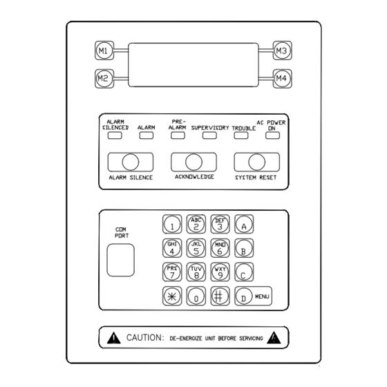
MPC-6000 / MPC-7000 / RND-2 INSTALLATION, OPERATION AND MAINTENANCE MANUAL CONTROL UNIT OPERATION OPERATION INSTRUCTIONS Standby Condition In normal standby operation, the green AC POWER ON LED should be illuminated and no other indicator operating. The display will show the system name, “System Normal”... -
Page 26: Trouble Conditions
MPC-6000 / MPC-7000 / RND-2 INSTALLATION, OPERATION AND MAINTENANCE MANUAL Operation of the ACKNOWLEDGE button within 15 seconds will add a number of seconds (60- 180) to the PAS timer. If the ACKNOWLEDGE button is not operated within 15 seconds, the system and user outputs activate. -
Page 27: Supervisory Conditions
MPC-6000 / MPC-7000 / RND-2 INSTALLATION, OPERATION AND MAINTENANCE MANUAL Supervisory Conditions In case of a supervisory condition, the system supervisory LED activates (ON – flashing) and the sounder activates (ON – pulsing). When the supervisory has been listed, the buzzer is silenced by pressing the “ACKNOWLEDGE”... -
Page 28: Additional Operating Procedures
MPC-6000 / MPC-7000 / RND-2 INSTALLATION, OPERATION AND MAINTENANCE MANUAL ADDITIONAL OPERATING PROCEDURES In addition to the basic fire alarm instructions above, several features are included to facilitate maintenance and increase the versatility of the system. Following are procedures to call up these functions. -
Page 29: History
MPC-6000 / MPC-7000 / RND-2 INSTALLATION, OPERATION AND MAINTENANCE MANUAL History The last 2000 system events are time-tagged and recorded for review in the user level event history. This history is available to anyone with the door key, but may be erased only at the maintenance security level. -
Page 30: Mpc-6000 / Mpc-7000 / Rnd-2 Operating Instructions
MPC-6000 / MPC-7000 / RND-2 INSTALLATION, OPERATION AND MAINTENANCE MANUAL MPC-6000 / MPC-7000 / RND-2 OPERATING INSTRUCTIONS Alarm Operation In case of alarm, the Alarm LED flashes, LCD displays alarm condition and the panel buzzer sounds steady. Local audible and visual signals and remote alarm signals operate. -
Page 31: Rdc-2 Operating Instructions
MPC-6000 / MPC-7000 / RND-2 INSTALLATION, OPERATION AND MAINTENANCE MANUAL RDC-2 OPERATING INSTRUCTIONS Alarm Operation In case of alarm, the Alarm LED flashes, LCD displays alarm condition and the buzzer activates on- steady. Local audible and visual signals and remote alarm signals operate. -
Page 32: Control Unit Installation
MPC-6000 / MPC-7000 / RND-2 INSTALLATION, OPERATION AND MAINTENANCE MANUAL CONTROL UNIT INSTALLATION PARTS SUPPLIED – MPC-6000 / MPC-7000 / RND-2 Enclosure Packages (Black or Red) • Backbox Assembly • Front Door Assembly with Window • Inner Door Assembly Electronics Package MPC-6000 / MPC-7000... -
Page 33: Control Unit Location
MPC-6000 / MPC-7000 / RND-2 INSTALLATION, OPERATION AND MAINTENANCE MANUAL 2. Disconnect all sources of power prior to installing or removing modules, connecting or disconnecting wiring and programming jumpers. CONTROL UNIT LOCATION The control unit should be located near an exit at ground level, where the normal ambient temperature is maintained within the control unit specification (See General Specifications). -
Page 34: Mpc-6000 And Rnd-2 Enclosure Mounting Pictures
• If a semi-flush mount installation is desired, use the SFTK-6(R/B) Semi-flush Trim for the MPC-6000 / RND-2 and the SFTK-7(R/B) Semi-flush Trim for the MPC-7000. The backbox can be mounted up to 3 1/2 inches into the wall. Place the semi-flush trim around the backbox and affix to the wall with four #10 x 3/4 inch wood screws (provided with trim). -
Page 35: Mpc-7000 Enclosure Mounting Pictures
MPC-6000 / MPC-7000 / RND-2 INSTALLATION, OPERATION AND MAINTENANCE MANUAL MPC-7000 Enclosure Mounting Pictures Remove Knock-Outs Prepare the enclosure for electrical wiring by breaking out the appropriate conduit entry points. Segregation is required between power limited and non-power limited conductors. In order to maintain the minimum separation, follow the wire routing illustrated on page 38. -
Page 36: Main Board Installation - P/N Mpc6-Mb / Mpc7-Mb
MPC-6000 / MPC-7000 / RND-2 INSTALLATION, OPERATION AND MAINTENANCE MANUAL Main Board Installation – P/N MPC6-MB / MPC7-MB Secure the board to the back of enclosure using the provided #6-32 x 1/4 screws (P/N 906- 220604). (Eight for the MPC6-MB and ten for the MPC7-MB.) -
Page 37: Bridge Rectifier Installation - P/N 130-Pm3223
MPC-6000 / MPC-7000 / RND-2 INSTALLATION, OPERATION AND MAINTENANCE MANUAL Bridge Rectifier Installation – P/N 130-PM3223 • Secure the bridge rectifier (P/N 130-PM3223) to the backbox, placing the thermal pad (P/N 330-944373) between the Bridge Rectifier and the backbox using a provided #6 keps nut (P/N 899-G67197). -
Page 38: Transformer Mounting - P/N Npe-1
MPC-6000 / MPC-7000 / RND-2 INSTALLATION, OPERATION AND MAINTENANCE MANUAL Transformer Mounting – P/N NPE-1 • Place the NPE-1 transformer assemblies (one for RND-2, two for MPC-6000 or MPC-7000) over the bottom one or two sets of studs on the left side of the enclosure, if desired. -
Page 39: Loop Driver Board(S) Mounting - P/N Fdlc
(four for the MPC-6000 and eight for the MPC-7000). • Carefully align connector J1 on the Loop Driver Board with connector J9 on the MPC-6000 Main Board (P/N MPC6-MB) or with connectors J9 and J14 on the MPC-7000 Main Board (P/N MPC7-MB). -
Page 40: Display Board Installation - P/N Mpc-Db Or Rnd2-Db
MPC-6000 / MPC-7000 / RND-2 INSTALLATION, OPERATION AND MAINTENANCE MANUAL Display Board Installation – P/N MPC-DB or RND2-DB • With the Inner Front Plate closed, carefully pass connector and cable from keypad through vertical slot in front plate. • Remove backing from keypad and carefully attach keypad to front plate. Center window in keypad on large opening in front plate. -
Page 41: Ground Wire Installation - P/N 600-149373
MPC-6000 / MPC-7000 / RND-2 INSTALLATION, OPERATION AND MAINTENANCE MANUAL Ground Wire Installation – P/N 600-149373 Attach Ground Wire (P/N 600-149373) to inside of outer door using provided #6 nut (P/N 950- 220604). Attach Ground Wire (P/N 600-149373) to outside of inner door using provided #6 screw (P/N 906-220604). -
Page 42: Battery Installation
Use the battery calculation chart to determine the battery size. Place the batteries in the space provided in the bottom of the backbox. If a battery set larger than12 AH (MPC-6000, RND-2) or 18 AH (MPC-7000) is required, a separate enclosure must be used. The Faraday 14050 may be used for battery sets 18 AH and smaller. -
Page 43: Control Unit Wiring Overview
If energy limited cable or equivalent is not used within the MPC-6000 / MPC-7000 / RND-2 enclosure, then the following guidelines do not apply. In that case, be sure to follow standard wiring practices. -
Page 44: Wiring Separation
MPC-6000 / MPC-7000 / RND-2 INSTALLATION, OPERATION AND MAINTENANCE MANUAL Wiring Separation All high voltage and non-power limited wiring must be kept separate from power limited wiring. A separation of at least a 1/4 inch must be maintained, with high voltage and non-power limited wiring running in separate conduit openings from power limited wiring. -
Page 45: Primary And Secondary Power Wiring
MPC-6000 / MPC-7000 / RND-2 INSTALLATION, OPERATION AND MAINTENANCE MANUAL Primary And Secondary Power Wiring The AC main connections (TB1) and the battery connections (J4) must be made along the left- hand side of the main termination board (P/N MPC6-MB or MCP7-MB). Route all high voltage and non-power limited wiring together and away from power limited wiring. -
Page 46: Mpc-6000 System Power Requirements (Does Not Include Nac Power)
MPC-6000 / MPC-7000 / RND-2 INSTALLATION, OPERATION AND MAINTENANCE MANUAL MPC-6000 System Power Requirements (Does not include NAC power) Device Item Max.(Amps) MPC- 6000 Amps MPC-6000 Control Unit (Includes 1 FDLC) 0.190 0.190 Addressable Device Circuit Power # of Devices X 0.0018 Amps... -
Page 47: Auxiliary Power Supply
MPC-6000 / MPC-7000 / RND-2 INSTALLATION, OPERATION AND MAINTENANCE MANUAL Auxiliary Power Supply *Connect an RSE-300 auxiliary supply when power requirement calculation indicates that an additional source is required. For further information, refer to Appendix D. Battery Size Calculations For calculation of battery size requirements see Appendix A. -
Page 48: Nac Wiring
MPC-6000 / MPC-7000 / RND-2 INSTALLATION, OPERATION AND MAINTENANCE MANUAL NAC Wiring At the lower right corner of the main board the terminal blocks TB12 and TB13 are used for the connection of notification appliances. Four individual NACs marked 1 through 4 are provided and the polarity shown is when the NAC is activated. -
Page 49: Serial Interface Circuit
MPC-6000 / MPC-7000 / RND-2 INSTALLATION, OPERATION AND MAINTENANCE MANUAL Serial Interface Circuit The serial interface circuit can address up to 16 standard annunciators and/or 8 remote processors to drive graphic annunciation or relay modules. Devices on the circuit may be connected up to 4000 feet from the control unit. -
Page 50: Serial Remote Device Wiring Overview
MPC-6000 / MPC-7000 / RND-2 INSTALLATION, OPERATION AND MAINTENANCE MANUAL Serial Remote Device Wiring Overview When connecting devices on the Serial Interface Circuit, the data wires must be daisy chained and with no T-taps to preserve the integrity of the data. Each end (two places) must be terminated with a 120 ohm termination resistor. -
Page 51: X1 Addresable Device Circuit(S)
MPC-6000 / MPC-7000 / RND-2 INSTALLATION, OPERATION AND MAINTENANCE MANUAL X1 Addresable Device Circuit(s) These devices are polled by the control unit every few seconds and input or output functions communicated to determine device status or function. The control unit monitors all device addresses for alarm and trouble conditions. -
Page 52: X1 Addressable Device Wiring Diagrams
LOOP CIRCUIT NOTE: Faraday X1 Devices: Detectors, Monitor Modules, or Control Modules up to a maximum of 252 devices per addressable device circuit. A Maximum of 20 devices recommended per Isolator Module. A Maximum of 12 Isolator Modules per addressable device circuit. - Page 53 POWER LIMITED NOTE: Faraday X1 Devices: Detectors, Monitor Modules, or Control Modules up to a maximum of 252 devices per addressable device circuit. A Maximum of 20 devices recommended between Isolator Modules. A Maximum of 12 Isolator Modules per addressable device circuit.
-
Page 54: Programming The Control Unit
PROGRAMMING THE CONTROL UNIT KEYPAD PROGRAMMING Customized programming of the control unit may be accomplished through the keypad in the control unit. See the Faraday MPC-6000 / MPC-7000 / RND-2 Programmer’s Manual, P/N 315-049403FA, for detailed information of system programming. PC PROGRAMMING Programming the panel may also be done by a temporary connection to the programming port with a computer. -
Page 55: Maintenance
MAINTENANCE GENERAL The MPC-6000 / MPC-7000 / RND-2 provides a maintenance mode to allow for the setting and controlling of various features in the system. Since the RND-2 does not have devices connected to it, some of these functions are not available on the RND-2. -
Page 56: Quick Test
MPC-6000 / MPC-7000 / RND-2 INSTALLATION, OPERATION AND MAINTENANCE MANUAL QUICK TEST If the control unit has remote connections to the Fire Department or other monitor, be sure to disable the remote signals and notify the remote monitoring station before performing test operations, since an off-normal condition will be indicated. -
Page 57: Appendix-A: Reference Data
MPC-6000 / MPC-7000 / RND-2 INSTALLATION, OPERATION AND MAINTENANCE MANUAL APPENDIX-A: REFERENCE DATA This appendix provides reference for the following topics: • Wire selection guides • Battery size calculations WIRE SELECTION GUIDES Resistance of Solid Copper Wire Ohms per Thousand Feet* 8.08... -
Page 58: Addressable Device Circuit Wire Selection Guide
Max Number of Devices Per Loop FDLC LINE RESISTANCE vs MAX NUMBER OF DEVICES Note: The total number of devices can not exceed 252. * The terminal blocks of Faraday X1 devices are rated for a maximum of 14AWG wire. -
Page 59: Battery Size Calculations
MPC-6000 / MPC-7000 / RND-2 INSTALLATION, OPERATION AND MAINTENANCE MANUAL BATTERY SIZE CALCULATIONS MPC-6000 Current Calculations Panel and Module Current Standby Current (A) Alarm Current (A) MPC-6000 Control Unit (includes one loop driver board) 0.190 0.190 CT-1K City Tie Standby 0.005... - Page 60 MPC-6000 / MPC-7000 / RND-2 INSTALLATION, OPERATION AND MAINTENANCE MANUAL TABLE 1 When using the CT-1K City Tie Board add the following currents for standby and alarm for features being used: Type of City Tie Connection Standby Alarm 1. Local Energy + 0.007...
-
Page 61: Auxiliary Module Battery Calculations
MPC-6000 / MPC-7000 / RND-2 INSTALLATION, OPERATION AND MAINTENANCE MANUAL Auxiliary Module Battery Calculations Panel and Module Current Standby Current (A) Alarm Current (A) RDC-2 Remote Standby 0.020 Annunciator Alarm 0.085 SRU-2 Serial Standby 0.032 Relay Unit Alarm 0.192 SRE-8 Serial Standby 0.000... -
Page 62: Total System Currents
1. An additional multiplier is included to compensate for the higher discharge rate in alarm. Battery capacity decreases with age. 2. The Standby current + Alarm current for an MPC-6000 must never exceed 3.0 Amps when using the two supplied transformers and 6.0 Amps when using the supplied transformers and the NPE-1 optional transformer assembly. -
Page 63: Appendix-B: Compatible Devices
Remote Lamp, Wall mount Notes: Faraday X1 devices, detectors and modules, up to a maximum of 252 addresses may be used per addressable X1 FDLC Loop Driver Circuit. For specific wiring and installation information, read the instructions provided with each device. -
Page 64: Devices For Notification Appliance Circuits
MPC-6000 / MPC-7000 / RND-2 INSTALLATION, OPERATION AND MAINTENANCE MANUAL DEVICES FOR NOTIFICATION APPLIANCE CIRCUITS The following lists compatible devices for the auxiliary power outputs. • Notification Appliances • Accessory Devices Notification Appliances Catalog Description Setting Max # per NAC... - Page 65 MPC-6000 / MPC-7000 / RND-2 INSTALLATION, OPERATION AND MAINTENANCE MANUAL 2884 (*5) Audible/Strobe Horn, 15cd 2884 (*5) Audible/Strobe Horn, 30cd 2884 (*5) Audible/Strobe Horn, 75cd 2884 (*5) Audible/Strobe Horn, 110cd 2884 (*5) Audible/Strobe Chime/Bell, 15cd 2884 (*5) Audible/Strobe Chime/Bell, 30cd...
- Page 66 MPC-6000 / MPC-7000 / RND-2 INSTALLATION, OPERATION AND MAINTENANCE MANUAL 6238 (*5) Strobe only 75cd 6238 (*5) Strobe only 110cd 6238 (*5) Horn/Strobe Horn, 15cd 6238 (*5) Horn/Strobe Horn, 30cd 6238 (*5) Horn/Strobe Horn, 75cd 6238 (*5) Horn/Strobe Horn, 110cd...
-
Page 67: Accessory Devices
MPC-6000 / MPC-7000 / RND-2 INSTALLATION, OPERATION AND MAINTENANCE MANUAL Accessory Devices Faraday Cat. Mfg. Part Number Description Faraday R711-1 711-1 Polarized Auxiliary Relay RSE-100 15070 Remote Signal Expander RSE 300 RSE-300 Remote Signal Expander 15222A 15222A Signal Expander Panel 1. -
Page 68: Appendix-C: Troubleshooting
MPC-6000 / MPC-7000 / RND-2 INSTALLATION, OPERATION AND MAINTENANCE MANUAL APPENDIX-C: TROUBLESHOOTING DEFINITIONS FOR EVENT HISTORY ENTRIES A. General ENTRY INDICATES ALARM General alarm ALRM Alarm AVCntr Alarm Verify counter Blank Plain alarm CrossZone cross zone point CZ1A Cross zone... -
Page 69: System Troubles
MPC-6000 / MPC-7000 / RND-2 INSTALLATION, OPERATION AND MAINTENANCE MANUAL B. System Troubles ENTRY INDICATES AC Trouble AC input low or off AddrLp 1 DBLSHT Double short trouble on addressable loop 1 AddrLp 1 OPEN Open circuit trouble on addressable loop 1... -
Page 70: System Events
MPC-6000 / MPC-7000 / RND-2 INSTALLATION, OPERATION AND MAINTENANCE MANUAL C. System Events ENTRY INDICATES/NOTES Alarm Silenced MAIN, LCDxx shown on bottom line All AV Ctrs Clr All AV counters cleared AutoProgram Run Auto programming function run Backup Cnfg Check... -
Page 71: Appendix-D: Module Installation Instructions List
MPC-6000 / MPC-7000 / RND-2 INSTALLATION, OPERATION AND MAINTENANCE MANUAL APPENDIX-D: MODULE INSTALLATION INSTRUCTIONS LIST This Appendix provides a list of installation instructions for the following option modules and accessories: • BE-1 Battery Box 315-033917FA • CT-1K City Tie Board 315-447052 •... -
Page 72: Appendix-E: Glossary
MPC-6000 / MPC-7000 / RND-2 INSTALLATION, OPERATION AND MAINTENANCE MANUAL APPENDIX-E: GLOSSARY Alarm Signal. A signal indicating an emergency requiring immediate action, such as an alarm for fire from a manual station, a waterflow alarm, or an automatic smoke detector. - Page 73 MPC-6000 / MPC-7000 / RND-2 INSTALLATION, OPERATION AND MAINTENANCE MANUAL General Alarm. A term usually applied to the simultaneous operation of all the notification appliances on a system. Ground Fault. A trouble condition in which a low resistance has been detected between the system wiring and conduit ground.
- Page 74 MPC-6000 / MPC-7000 / RND-2 INSTALLATION, OPERATION AND MAINTENANCE MANUAL Waterflow Switch. An assembly approved for service and so constructed and installed that any flow of water from a sprinkler system equal to or greater than that from a single automatic sprinkler head will result in activation of this switch and subsequent indication of an alarm condition.
- Page 76 Siemens Building Technologies, Inc. 8 Fernwood Road • Florham Park, NJ 07932 Tel: (973) 593-2600 • Fax: (973) 593-6670 Web: www.faradayfirealarms.com P/N 315-447309-5...
Need help?
Do you have a question about the MPC-6000 and is the answer not in the manual?
Questions and answers