
Subscribe to Our Youtube Channel
Related Manuals for Ariterm BioComp-series


Summary of Contents for Ariterm BioComp-series
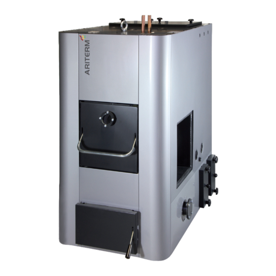
- Page 1 INSTALLATION, OPERATION AND MAINTENANCE For a sustainable future. • BioComp 40 - 300 kW...
-
Page 2: Table Of Contents
TABLE OF CONTENTS General ......................3 Contents of delivery ..................3 Transportation, storage and opening the package ........4 Technical data ....................5 Dimensions ....................6 Boiler installation ..................7 Pipe installation ..................8-9 Electrical installation ................10-12 Flue gas fan installation ................13 Burner installation ..................14 Ash screw installation .................15-16 Commissioning ..................17... -
Page 3: General
General The BioComp-series bio boiler is economical, manageable and environmentally friendly. All the boilers in the series are available as either right or left handed, with maintenance and ash removal hatches in front. The boiler is equipped with an integrated ash chamber as standard. -
Page 4: Transportation, Storage And Opening The Package
TRANSPORTATION, STORAGE AND OPENING THE PACKAGE Reception The boiler is delivered in a wooden frame. It is on a platform from which the boiler can be lifted safely. The package should be opened as close to the installation site as possible. The boiler has been insured against possible transport damage from the factory to the first point of storage by the manufacturer. -
Page 5: Technical Data
TECHNICAL DATA Convector maintenance hatch Burner opening Flue gas fan Viewing screen (can also be installed in place of Maintenance hatch convector ash hatch) Convector ash hatches Ash hatch Fire chamber ash screw (accessory) BioComp BioComp BioComp BioComp BioComp Boiler Power, kW Weight, kg 1035... - Page 6 TECHNICAL DATA Convector maintenance hatch Burner opening Flue gas fan Viewing screen (can also be installed in place of Maintenance hatch convector ash hatch) Convector ash hatches Ash hatch Fire chamber ash screw (accessory) BioComp BioComp BioComp Boiler Power, kW Weight, kg 1550 1950...
-
Page 7: Dimensions
DIMENSIONS 1. Boiler water overheating protection DN 15 14. Electric resistance connection DN 50 2. Spare DN 15 15. Drain connection DN 20 3. Boiler water temperature sensor DN 15 16. Burner opening, right or left side 4. Fire chamber sensor connection DN 15 (BC40 DN 20) 17. -
Page 8: Boiler Installation
BOILER INSTALLATION The installation of the boiler can only be conducted by a professionally qualified installer. The installation should be carried out so that it fills at least the country’ s minimum requirements applicable to heating systems in question. The boiler’ s electrical installations can only be carried out by a professional with the required proficiencies. -
Page 9: Pipe Installation
PIPE INSTALLATION Pipe installations The BioComp -boiler has been designed to operate without an accumulator tank. The boiler has a large water capacity and it has its own heat exchanger for production of domestic hot water. It is, however, possible to install an accumulator tank if the boiler is used intermittently or momentary peaks in consumption such require. -
Page 10: Domestic Hot Water Production
PIPE INSTALLATION Safety valve installation (not included in the delivery) The valve must be CE-marked with the maximum opening pressure of 3,0 bars and the minimum size of DN 25. The safety valve must be chosen according to the highest pressure class of the device combination. Do not install a closing device (valve or similar) between the valve and the boiler. -
Page 11: Electrical Installation
ELECTRICAL INSTALLATION The standard features of the BioComp 40 - 150 kW -boilers include a heat exchanger pump and an automatic cleaning. These have been connected to the terminal box at the factory. The flue gas fan is also a standard feature on 40 - 150 kW models. The fan can in 60-150 kW models be installed either at the back of the boiler or on the side instead of the ash hatch. -
Page 12: Wiring Diagram
WIRING DIAGRAM Terminal box 1. Open the two screws at the bottom of the 2. Open the front panel fastening screws front panel of the boiler. located on the top of the boiler. 3. Cleaning motor (10) and heat exchanger pump (11) terminal box. -
Page 13: Flue Gas Fan Installation
FLUE GAS FAN INSTALLATION The boiler is supplied with a flue gas fan. Install the fan on suitable side of the boiler (either at the back or on either side instead of the rearmost convector ash hatches). Delivery includes: - Flue gas fan (includes capacitor case) - Flue pipe between the boiler and the fan (including bolts) - Flue duct extension pipe from fan to chimney Installation... -
Page 14: Burner Installation
BURNER INSTALLATION The burner is installed to the burner opening on the side of the boiler. MultiJet burner fits directly to the opening. Burner flanges for BioJet and HakeJet burners, Axon/PX52-pellet burners and oil burners (BioComp 60 only) are available as accessories. The gap between the burner and the flange must be sealed with heat resistant sealant paste. -
Page 15: Ash Screw Installation
ASH SCREW INSTALLATION Push the primary ash screw inside the boiler. Install the ash screw thrust bearing. Install the motor adapter flange with four Install the ash screw adapter flange onto the M8x25 countersunk screws. motor adapter flange. Insert the motor into the primary screw shaft. Push the motor into the mounting flange. - Page 16 ASH SCREW INSTALLATION Fasten the motor with four M10 hex nuts into Fasten the motor into the ash screw shaft with the mounting flange M10x20 hex nut. Tighten the hex nut carefully. Install the bearing cover plate. Ash screw with extension piece. Ash screw with ash box.
-
Page 17: Commissioning
COMMISSIONING Before starting up the heating system the following must be checked: • the heating network and the boiler are full of water, pressure at least 0,5 bar • the damper plate is open, if applicable • the circulation pump is in operation •... -
Page 18: Maintenance
MAINTENANCE Maintenance intervals The following maintenance intervals are indicative and may vary considerably according to the chosen fuel and the heat load. Note that keeping up a very small fire stains the boiler heavily. At first the maintenance is to be performed more reqularly in order to determine the suitable interval for the maintenance. - Page 19 MAINTENANCE Ash removal from fire chamber Ash removal from convection part Check the fire chamber ash compartment1-2 Check the ash compartments of the convection times a month and remove the ash with an ash part once a month and remove the ash with rake if required.
-
Page 20: Maintenance
MAINTENANCE Checking the convection part The boiler has been equipped with an Check the pipes of the convector and remove automatic convector cleaning but the fly ash from the surfaces. Test that the spirals convection part should be checked 2-3 times move freely in the pipes. -
Page 21: Warranty, Decommissioning And Contact Information
18 months from the delivery date. The warranty for the pressure vessels manufactured by Ariterm is 5 years from the date of delivery. Ariterm will deliver new parts to replace the faulty ones and the warranty applies to possible manufacturing and material defects. -
Page 22: Standard Delivery
STANDARD DELIVERY Component Prod. code/picture Fire chamber brush 3487 Convection pipe sweeping brush 3489 Sweeping brush arm 3492 Fire chamber brush arm 1356 Ash rake 8530 Wall holder for cleaning equipment Flue gas thermometer 5883 Temperature/pressure gauge, 1/2’’ 5885 Flue gas fan Ventur TH (BioComp 60-150) Adapter (Flue pipe) (BioComp 60-80) A3000-310d Adapter (Flue pipe) (BioComp 120-150) -
Page 23: Accessories
ACCESSORIES BioComp 40 kW accessories Product code Primary ash screw (incl. motor 0,55 kW) SBCOM40-230 Primary ash screw with extra length (incl. motor 0,55 kW) SBCOM400000 BeQuem 40 flange A3040-469B och FJ50-154A BioComp 60 kW accessories Product code Oil burner kit (incl. adapter flange, d100 mm opening, mountings) A3060-478 HakeJet / BioJet -kit (incl. - Page 24 ACCESSORIES BioComp 200 kW accessories Product code HakeJet / BioJet -kit (incl. adapter flange, mountings) BCOM200-420 Primary ash screw (incl. motor 0,55 kW) SBCOM200-230 Primary ash screw with extra length (incl. motor 0,55 kW) SBCOM200000 BioComp 250 kW accessories Product code HakeJet / BioJet -kit (incl.
-
Page 25: Spare Parts
SPARE PARTS Prod. code Cleaning equipment Boiler 1356 Fire chamber brush arm d10 x M12 40-300 kW 3487 Fire chamber brush 40-300 kW 3492 Sweeping brush arm 40-300 kW 3492 Sweeping brush 40-300 kW 8530 Ash rake 40-300 kW Prod. code Electric components Boiler 5660... - Page 26 SPARE PARTS Prod. code Hatches Picture code Boiler Z10589 Convection part ash hatch 40 - 80 kW Z13610 Convection part ash hatch 120 - 150 kW Convection part hatch BioComp 40 BCOM40-36 40 kW Z19018 Convection part hatch BioComp 60 BCOM60-36B 60 kW Z19019...
-
Page 27: Notes
NOTES... - Page 28 NOTES...
- Page 29 NOTES...
- Page 32 ORGANISATION CERTIFIED BY ARITERM OY | PL 59 (Uuraistentie 1), 43101 Saarijärvi, Finland Tel +358 14 426 300, fax +358 14 422 203 | www.ariterm.fi...
Need help?
Do you have a question about the BioComp-series and is the answer not in the manual?
Questions and answers
Can you go back in time to read the meter on this boiler