Table of Contents
Advertisement
Quick Links
XPS036
Model:
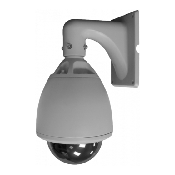
True Day/Night 550/600 TVL Speed
Dome CCTV Camera with 36x Zoom
PLEASE READ THIS MANUAL BEFORE YOU INSTALL OR START USING THE XPS036 SPEED DOME
This equipment generates, uses, and can radiate radio frequency energy and, if not installed and used in accordance with the
instruction manual, may cause harmful interference to radio communications. Operation of this equipment in a residential area is
likely to cause harmful interference in which case the user will be required to correct the interference at the user's own expense.
PRECAUTIONS:
z Only qualified and experienced person can carry out the installation. In many countries and areas licensed personnel is required
z Always take safety codes into consideration during installation.
z Use reliable tools only, poor quality tools may cause damage to both human and property
z Check the strength of all item onsite that are related to installation in advance. It is recommended that the stand of dome be at
least 4 times stronger than the weight of the dome and its accessories.
z Keep all the original dome package materials in case of future repacking and transportation.
z Choose and install speed dome according to environment requirement (Refer to the Product Features).
WARNINGS:
z Avoid installing this speed dome in hazardous places where inflammable or explosive materials are stored or used.
z Indoor dome is not designed for outdoor environment.
z This speed dome runs on 24V AC.
z Connect to power only after completing installation.
z Disassemble can only be carried out by qualified personnel.
z Use soft towel to clean the down cover when necessary. Avoid using caustic detergent.
z Avoid aiming camera to strong light.
XPS036
Model:
True Day/Night 550/600 TVL Speed
Dome CCTV Camera with 36x Zoom
Advertisement
Table of Contents

Related Manuals for XVision XPS036


Summary of Contents for XVision XPS036
- Page 1 Dome CCTV Camera with 36x Zoom PLEASE READ THIS MANUAL BEFORE YOU INSTALL OR START USING THE XPS036 SPEED DOME This equipment generates, uses, and can radiate radio frequency energy and, if not installed and used in accordance with the instruction manual, may cause harmful interference to radio communications.
-
Page 2: Table Of Contents
INDEX PRODUCT DESCRIPTION Camera Parameters FEATURES 5.5.1 Sensetivity INSTALLATION 5.5.2 AE Mode Installation Preparation 5.5.3 Preset Freeze 3.1.1 Cables 5.5.4 White Balance 3.1.2 DIP Switches & Jumper settings 5.5.5 BLC Mode 3.1.3 Wiring Diagram 5.5.6 Video Phase Wall Mounting Guide 5.5.7 Focus Min. -
Page 3: Product Description
Infra Red lighting). This camera is designed for use in very high risk applications where very high quality surveillance is required and features an Xvision Auto Iris Zoom Lens with Auto Focus and 432x Zoom (36x Optical + 12x Digital) for easy selection of any viewing angle between 0.5 and 64°. -
Page 4: Installation
3. Installation 3.1 Installation Preparation You may need the following tools for the installation: Screws and nuts, screw driver, Small slotted screw driver, Wire cutter, Ladder, Drill, Saw. 3.1.1 Cables z Video Coaxial Cable z RS485 (Data) Cable The video coaxial cable should be: 0.56mm (24AWG) twisted pair ’s maximum transmission distances are as follows: 1) 75 Ohm impedance. -
Page 5: Wall Mounting Guide
3.2 Wall Mounting Guide 4. Install housing ADDITIONAL MOUNTING BRACKETS ARE AVAILABLE Insert cables through the FOR CORNER MOUNT, PENDANT CEILING MOUNT AND hole at the top of the housing POLE MOUNTING OPTIONS. Apply water-proof tape to the REFER TO THE MANUAL SUPPLIED WITH THE BRACKETS FOR FURTHER housing thread. -
Page 6: System Connection
4. System Connection... -
Page 7: Operating Instructions
5. Operating Instructions Two methods are available for carrying out the operation by the system controller. 1. Press the combined hot keys to operate different functions. Refer to the system controller manual for the detailed commands. 2. Access the OSD menu and operate according to the following instructions. INITIAL INFORMATION When you power up or restart the dome, the initial information below will display on screen when the dome is conducting self- testing. - Page 8 5.1.1 Menu Tree System Information 1. Dome Information 2. Disp Information 3. Init Information 4. Change Password 5. Language Select 6. Factory Default 7. Restart 0. Exit Lens Parameters 1. Zoom Speed :High 2. Digital Zoom :Off 3. Joystick Auto :Both 4.
-
Page 9: Menu Operation
5.2 Menu Operation 5.2.1 Selecting Items In the main menu, the cursor flashes on the left, move the joystick up or down to move the cursor to the desired setting item. Move the joystick to the right to select the item. Select an item to: 1. -
Page 10: Editing Titles
5.2.3 Editing Titles Access Dome Title Edit Menu following the path: System menu > Dome Information > Title > Input Move the cursor left or right to select a character, move down to edit the blinking character. Zoom In/out to switch character groups: z Number [0 1 2 3 4 5 6 7 8 9 ] z Capital [A B C ] z Lowercase [a b c ]... -
Page 11: Display Information
5.3.2 Display Information System Menu > System Information > Display Information Display Configuration 1. Title Information 2. Other Information 0. Back z Title Information Title Information 1. Dome Title : Off 2. Preset Title : Off 3. Pattern Title : Off 4. -
Page 12: Init Information
Information text Position Dome Title Pan degree Preset/Pattern/Panning Title Region Title P134 T74 16.25.06 Time Fan Alert Zoom Times Alarm Alert Vertical Tilt Value (degrees) Horizontal Pan Value (degrees) Note: Fan symbol indicates fan speed below 1000 rounds/min. Alarm symbol indicates an alarm comes in. 5.3.3 Init Information System Menu >... -
Page 13: Language Select
5.3.5 Language Select System Menu > System Information > Language Select Language Select Language : English Select one language. 5.3.6 Factory Default System Menu > System Information > Factory Default Select Factory Default to restore factory default settings. System will request password to set it. Factory default will not change dome ID. -
Page 14: Lens Parameters
5.4 Lens Parameters System Menu > Lens Parameters Lens Parameters 1. Zoom Speed :High 2. Digital Zoom :Off 3. Joystick Auto :Both 4. Auto Focus 5. Auto Iris 6. Iris ALC :084 7. Iris PLC :016 8. Day Might Mode :Auto 9. -
Page 15: Iris Alc
5.4.6 Iris ALC To set the iris average level control value. The value could be 000~255. z Default value: 22X Colour Camera: 066, 23X Colour/Mono camera: 084 (different camera has different ALC default value) Note: Changing default value is strongly NOT recommended. 5.4.7 Iris PLC To set the iris peak level control value. -
Page 16: Ae Mode
5.5.2 AE Mode System Menu > Camera Parameters > AE Mode Exposure Mode 1. Mode :Auto 2. Shutter :N/A 3. Iris :N/A 4. AGC :N/A 0. Back z Mode - The value options are: Auto, Shutter, Iris and AGC. The setting will take priority overall other settings. z Shutter - Set Shutter speed as priority, available: settings are 1/1.5, 1/3, 1/6, 1/12, 1/25, 1/100, 1/150, 1/250, 1/500, 1/1000, 1/2000, 1/4000, 1/10000, 1/30000... -
Page 17: Preset Freeze
5.5.3 Present Freeze System Menu > Camera Parameters > Preset Freeze Preset Freeze Setup Preset Freeze: Off If Preset Freeze is On, the current image will freeze until the image of the preset presents. Therefore you can not see the scene between the current position and the preset. -
Page 18: Video Phase
5.5.6 Video Phase System Menu > Camera Parameters > Video Phase Video Phase Phase : Off z OFF: Disable this function. z 001~360: Choose the suitable phase to get synchronous video. Note: Some models only have ON/OFF. 5.5.7 Focus Min Limit System Menu >... -
Page 19: Speed Adjust
5.6.2 Speed Adjust Some protocols’ controlling speed is either faster or slower, set Speed Adjust to adjust the dome movement. Options are as below: z X1: Original speed (default setting) z 2 ~ 32: Times faster than original speed. z 2 ~ 32: Times slower than original speed. 5.6.3 Proportion Direction PT The dome moves at a speed of certain degrees per second. -
Page 20: Auto Running
5.7 Auto Running System Menu > Auto Running Setup Auto Running Setup 1. Preset Setup 2. Sequence 3. Pattern Setup 4. Panning Setup 5. Region Setup 6. Idle Time Setup 7. Auto Action Setup 0. Back 5.7.1 Preset Setup System Menu > Auto Running Setup > Preset Setup Preset Setup 1. -
Page 21: Sequence
5.7.2 Sequence System Menu > Auto Running Setup > Sequence Setup Sequence 1. Number :001 2. Dwell :003 3. Edit 4: Show 5. Run 6. Delete 0. Back A “sequence” is defined as a sequencial moving from preset to preset and dwell for a specific time at each preset. It is useful if you need to repeat switching among a number of presets. -
Page 22: Panning Setup
A pattern records a continuous movement of the camera in a period of time. The difference between sequence and pattern is that in a sequence, dome moves from a preset to next at a fixed speed; in a pattern, dome moves flexible curve at various speed. Speed Dome can record 4 patterns, minimum 180 seconds each pattern. -
Page 23: Region Setup
z End: To set the ending position. Set it in the same way as Start. z Speed: Sets the panning speed (Dome movement speed). Value ranges from 001 to 255, the higher value represents the higher speed. Pan right to select, tilt up or down to change value. z Show: To run the current panning once, use this function to check the panning z Run: To run the panning continuously. -
Page 24: Auto Action Setup
5.7.7 Auto Action Setup System Menu > Auto Running Setup > Auto Action Setup Auto Action Setup Auto Action :Off Auto action refers to the function that system will automatically run when idle time is out. Setting include: z OFF: Disable this function z Preset (1~220): Call preset 001~220 z Panning (1~4): Run panning 001~004 z Sequence (1~4): Run sequence 001~004... -
Page 25: Privacy Masking
5.9 Privacy Masking System Menu > Privacy Masking Privacy Masking 1. Mask No 2. Setting 3. Activate Empty 4. Delete 0. Back The feature of privacy masking can be used to protect public privacy. e.g. a resident’s window, a toilet. Integrated Speed Dome can cover a black square on some particular locations. -
Page 26: Alarm Setup
Method B The setting has two steps: 4. Choose area Move the cross to the centre of desired position, call preset 1 to save the position then go to step 2 or call preset 2 to cancel. Call Preset 1 :Save Call Preset 2 :Cancel Move Dome 5. - Page 27 Appendix I: DIP Switch & Jumper Settings This appendix guides you to set protocol, baud rate, dome This speed dome supports multi-protocol. The setting chart address, video cable type, alarm output and resistor jumper. is shown below, O means ON, blank means OFF, X means either ON or OFF.
- Page 28 DOME ADDRESS SETTING ADDRESS SETTING CHART O means ON, blank means OFF. The control commands contain target dome’s ID. The dome Switch Number only reacts to the command sent to its own address or broadcast address. So, each dome should be assigned an address.
- Page 29 Switch Number Switch Number...
- Page 30 Switch Number Switch Number...
- Page 31 Switch Number Programmable Address...
- Page 32 ALARM OUTPUT METHOD SETTING There are two alarm output methods: NO and NC. NO means normal state is open circuit, the circuit will be closed when an alarm comes in. NC means normal close circuit. When choosing pins 1&2 in JP6 and JP7,the alarm output state is NC.
-
Page 33: Transmission Distance Comparison Chart
Appendix 2: Wire Diameter & Transmission Distance Comparison Chart The transmission distance listed below are farthest ones recommended for each given wire diameter when the 24V AC voltage loss ratio is below 10% (for equipment powered by AC, the allowed maximum voltage loss ratio is 10%).For example, a set of equipment with nominal power as 80VA, installed 35 feet (10m) away from transformer, needs a wire with a minimum diameter of 0.8000mm. -
Page 34: Basic Knowledge
Appendix 3: RS485 Bus Basic Knowledge 1. CHARACTERISTICS OF RS485 BUS 3.2 The connection of 120 Ohm termination resistor: The termination resistor is ready on the Protocol PCB. There As specified by RS485 standards, RS485 Bus is of half- are two kinds of connection. Please refer to the Protocol PCB duplexed data transmission cables with characteristic jumper setting form (refer to following pictures). - Page 35 RS485 standards, problems such as signal NOTE: The RS485 distributor is not supplied with reflections, lower anti-interference performance arise when the XPS036 Speed Dome. the cables are long in the connection. The new connection achieves reliable data transmission...
-
Page 36: Proof & Surge Proof
Appendix 4: Lightning Proof & Surge Proof The product adopts TVS lightning proof technology to prevent from damage by lightning strike below 4000V and impulse signals such as surge; but it is also necessary to abide by the following precautions to ensure electrical safety based on practical circumstances: z Keep the communication cables at least 50 meters away from high voltage equipment or cables. -
Page 37: Of The Dome Cover
Appendix 5: The Cleaning Of the Dome Cover To obtain constant clear videos, user should clean the down cover periodically. z Be cautious when cleaning. Hold the down cover ring only to avoid direct touch to the acrylic down cover. The acid sweat mark of fingerprint will corrode the coating of down cover and scratch on down cover will cause blurred/unclear images. - Page 38 Appendix 6: Troubleshooting Problem Possible Cause Solution 1. If the red LED on the power board in the 1. Check if the power supply is connected, or housing is NOT lit, causes may be: confirm if the plug contacts well - The 24V AC power supply is not connected to the port of the power board or the 2.
- Page 39 Appendix 7: Specifications Model: XPS036 Picture Type: Day/Night (B/W & Colour) Image Sensor: Sony 1/4” Ex View CCD DSP: Xvision XX2 Resolution: 550/600 TVL Minimum Illumination: 0.1 Lux Lens Type: Auto Iris Lens Size: 3.4 to 122.4mm Lens Viewing Angle: 0.5 to 64°...
-
Page 40: Limited Warranty
TECHNICAL SUPPORT: For Technical Support for any Xvision product please contact your local distributor. LIMITED WARRANTY: This product is supplied with a 1 Year warranty. The Warranty excludes products that have been misused, (including accidental damage) and damage caused by normal wear and tear. In the unlikely event that you encounter a problem with this product, it should be returned to the place of purchase.
Need help?
Do you have a question about the XPS036 and is the answer not in the manual?
Questions and answers