Table of Contents
Advertisement
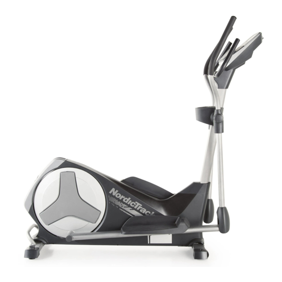
Model No. NTEVEL99812.0
Serial No.
USER'S MANUAL
Write the serial number in the space
above for reference.
Serial Number
Decal
CUSTOMER SERVICE
UNITED KINGDOM
Call: 08457 089 009
From Ireland: 053 92 36102
Website: www.iconsupport.eu
E-mail: csuk@iconeurope.com
Write:
ICON Health & Fitness, Ltd.
c/o HI Group PLC
Express Way
CASTLEFORD
WF10 5QJ
UNITED KINGDOM
AUSTRALIA
Call: 1800 993 770
E-mail: australiacc@iconfitness.com
Write:
ICON Health & Fitness
PO Box 635
WINSTON HILLS NSW 2153
AUSTRALIA
CAUTION
Read all precautions and instruc-
tions in this manual before using
this equipment. Keep this manual
for future reference.
www.iconeurope.com
Advertisement
Table of Contents

Related Manuals for NordicTrack E9.2 NTEVEL99812.0


Summary of Contents for NordicTrack E9.2 NTEVEL99812.0
- Page 1 Model No. NTEVEL99812.0 Serial No. USER’S MANUAL Write the serial number in the space above for reference. Serial Number Decal CUSTOMER SERVICE UNITED KINGDOM Call: 08457 089 009 From Ireland: 053 92 36102 Website: www.iconsupport.eu E-mail: csuk@iconeurope.com Write: ICON Health & Fitness, Ltd. c/o HI Group PLC Express Way CASTLEFORD...
-
Page 2: Table Of Contents
If a decal is missing or illegible, see the front cover of this manual and request a free replacement decal. Apply the decal in the location shown. Note: The decal(s) may not be shown at actual size. NORDICTRACK is a registered trademark of ICON IP, Inc. -
Page 3: Important Precautions
IMPORTANT PRECAUTIONS WARNING: To reduce the risk of serious injury, read all important precautions and instructions in this manual and all warnings on your elliptical before using your elliptical. ICON assumes no responsibility for personal injury or property damage sustained by or through the use of this product. -
Page 4: Before You Begin
BEFORE YOU BEGIN Thank you for purchasing the NORDICTRACK E 9.2 manual. To help us assist you, note the product model ® elliptical. The E 9.2 elliptical provides an array of fea- number and serial number before contacting us. The... -
Page 5: Part Identification Chart
PART IDENTIFICATION CHART Use the drawings below to identify the small parts needed for assembly. The number in parentheses below each drawing is the key number of the part, from the PART LIST near the end of this manual. The number following the key number is the quantity needed for assembly. -
Page 6: Assembly
ASSEMBLY • Assembly requires two persons. • In addition to the included tool(s), assembly requires the following tool(s): • Place all parts in a cleared area and remove the one Phillips screwdriver packing materials. Do not dispose of the packing materials until you finish all assembly steps. - Page 7 3. While a second person lifts the front of the Frame (1), attach the Front Stabilizer (73) to the Frame with two M10 x 95mm Screws (82). 4. Orient the Upright (2) and the Top Shield Cover (37) as shown. Slide the Top Shield Cover upward onto the Upright.
- Page 8 5. Slide the Upright (2) onto the Frame (1). Tip: Have a second person hold the Top Shield Cover (37) out of the way. Tip: Avoid pinching the Wire Harness (42). Attach the Upright (2) with four M10 x 20mm Screws (79) and four M10 Split Washers (78).
- Page 9 7. While a second person holds the Console (4) near the Upright (2), connect the console wires Avoid pinching to the Wire Harness (42), the Pulse Wire (28), the wires and the Monitor Wire (103). Insert the excess wires into the Upright (2) or Console Wires into the Console (4).
- Page 10 9. Identify the Left and Right Upper Body Arms (8, 9). Orient the Left Upper Body Arm (8) and an Upper Body Leg (6) as shown. Make sure that the hexagonal holes are in the indicated location. Insert the Left Upper Body Arm (8) into the Upper Body Leg (6).
-
Page 11: Apply A Small Amount Of Grease To A Shoulder
10. Apply a generous amount of the included grease to the axles on the Upright (2). Orient the Left and Right Upper Body Arms (8, 9) as shown, and slide them onto the left and right sides of the Upright (2). Attach each Upper Body Arm (8, 9) with an M8 x 20mm Screw (80) and an M8 Washer (33). - Page 12 12. See the inset drawing. Identify a Pivot Cover A (19), which has hooks, and a Pivot Cover B (22), which has tabs. Press a Pivot Cover A (19) and a Pivot Cover B (22) together around the Right Upper Body Arm (9).
- Page 13 14. Press a Front Leg Cover (20) and a Rear Leg Cover (21) together around the right Upper Body Leg (6). Repeat this step for the other side of the elliptical. 15. Identify the Right Pedal (13). Attach the Right Pedal (13) to the Right Pedal Arm (49) with three M10 x 48mm Screws (75) and three M10 Split Washers (78).
- Page 14 16. See the upper drawing. Press the Rear Shield Cover (59) onto the Left and Right Shields (44, 45). Plug the Power Adapter (100) into the Power Receptacle (104) on the Frame (1). If necessary, plug the Power Adapter (100) into the Plug Adapter (101).
-
Page 15: The Chest Heart Rate Monitor
THE CHEST HEART RATE MONITOR HOW TO PUT ON THE HEART RATE MONITOR • Do not expose the heart rate monitor to direct sun- light for extended periods of time; do not expose it to The heart rate temperatures above 122° F (50° C) or below 14° F monitor consists of (-10°... -
Page 16: How To Use The Elliptical
HOW TO USE THE ELLIPTICAL HOW TO PLUG IN THE POWER ADAPTER HOW TO MOVE THE ELLIPTICAL IMPORTANT: If the elliptical has been exposed to Due to the size and weight of the elliptical, moving cold temperatures, allow it to warm to room tem- it requires two persons. - Page 17 HOW TO EXERCISE ON THE ELLIPTICAL Push the pedals until they begin to move with a continuous motion. Note: The pedal discs can turn To mount the elliptical, hold the handlebars or the in either direction. It is recommended that you move the pedal discs in the direction shown by the upper body arms and step onto the pedal that is in the arrow;...
- Page 18 CONSOLE DIAGRAM MAKE YOUR FITNESS GOALS A REALITY WITH IFIT.COM With your new iFit-compatible fitness equipment, you can use an array of features on iFit.com to make your fitness goals a reality: Exercise anywhere in the world with customizable Google Maps. Download training workouts designed to help you reach your personal goals.
- Page 19 FEATURES OF THE CONSOLE The console also features an iFit mode that enables the console to communicate with your wireless network The advanced console offers an array of features through an optional iFit module. With the iFit mode, designed to make your workouts more effective and you can download personalized workouts, create your enjoyable.
- Page 20 HOW TO USE THE MANUAL MODE Calories per Hour (Cals./Hr)—This display mode will show the approximate number of calories you 1. Begin pedaling or press any button on the are burning per hour. console to turn on the console. Distance (Dist.)—This display mode will show When you turn on the console, the display will turn the distance that you have pedaled in miles or on.
- Page 21 If there are As you exercise, the workout intensity level bar will indicate the approximate intensity level of your sheets of plastic exercise. on the metal contacts on the handgrip heart rate monitor, remove the Contacts plastic. To mea- sure your heart rate, hold the Press the Home button to return to the default handgrip heart...
- Page 22 HOW TO USE AN ONBOARD WORKOUT resistance level and/or target speed is programmed for the next segment, the resistance level and/or 1. Begin pedaling or press any button on the target speed will appear in the display for a few console to turn on the console.
- Page 23 HOW TO USE A SET-A-GOAL WORKOUT Make sure to pedal at a speed that is comfort- able for you. 1. Begin pedaling or press any button on the console to turn on the console. Note: The calorie goal is an estimate of the number of calories that you will burn during When you turn on the console, the display will turn the workout.
- Page 24 HOW TO USE A WATTS WORKOUT Watts workout 2 or 3 is divided into one-minute segments. One resistance level and one watts 1. Begin pedaling or press any button on the goal are programmed for each segment. Note: The console to turn on the console. same resistance level and/or watts goal may be programmed for consecutive segments.
- Page 25 HOW TO USE AN IFIT WORKOUT 4. Select an iFit workout. You must have an iFit module to use an iFit workout. To download an iFit workout in your schedule, press the Map, Train, or Lose Wt. button to down- To purchase an iFit module at any time, go to load the next workout of that type in your schedule.
- Page 26 5. Start the workout. HOW TO USE THE SOUND SYSTEM See step 3 on page 22. To play music or audio books through the console sound system while you exercise, plug your audio During some workouts, the voice of a personal cable into the jack on the console and into a jack on trainer will guide you through your workout.
- Page 27 HOW TO CHANGE CONSOLE SETTINGS If no module is connected, the display will show the words NO IFIT MODULE. If no module is con- The console features a user mode that allows you to nected, go to step 10. view usage information, select a unit of measurement, 6.
-
Page 28: Maintenance And Troubleshooting
MAINTENANCE AND TROUBLESHOOTING Inspect and tighten all parts of the elliptical regularly. Replace any worn parts immediately. To clean the elliptical, use a damp cloth and a small amount of mild soap. IMPORTANT: To avoid damage to the console, keep liquids away from the console and keep the console out of direct sunlight. - Page 29 HOW TO ADJUST THE REED SWITCH Locate the Reed Switch (58). Loosen, but do not remove, the M4 x 16mm Screw (92). If the console does not display correct feedback, the reed switch should be adjusted. To adjust the reed switch, you must remove the right disc cover and the right pedal disc.
-
Page 30: Exercise Guidelines
EXERCISE GUIDELINES Burning Fat—To burn fat effectively, you must exer- WARNING: cise at a low intensity level for a sustained period of Before beginning this time. During the first few minutes of exercise, your or any exercise program, consult your physi- body uses carbohydrate calories for energy. - Page 31 SUGGESTED STRETCHES The correct form for several basic stretches is shown at the right. Move slowly as you stretch; never bounce. 1. Toe Touch Stretch Stand with your knees bent slightly and slowly bend forward from your hips. Allow your back and shoulders to relax as you reach down toward your toes as far as possible.
-
Page 32: Part List
PART LIST Model No. NTEVEL99812.0 R0113A Key No. Qty. Description Key No. Qty. Description Frame Leveling Foot Upright Rear Stabilizer Cap Rear Upright Cover Right Pedal Arm Console Wheel Water Bottle Holder Flywheel Upper Body Leg Idler Resistance Wheel C-magnet Left Upper Body Arm Resistance Motor Right Upper Body Arm... - Page 33 Key No. Qty. Description Key No. Qty. Description Pulse Sensor Monitor Receiver/Wire Flywheel Bearing Power Receptacle/Wire Leveling Knob Sensor Unit M4 x 19mm Screw Chest Strap Right Stabilizer Cap M8 x 15mm Screw Left Stabilizer Cap Small Snap Ring M4 x 28mm Screw –...
-
Page 34: Exploded Drawing
EXPLODED DRAWING A Model No. NTEVEL99812.0 R0113A... - Page 35 EXPLODED DRAWING B Model No. NTEVEL99812.0 R0113A...
-
Page 36: Ordering Replacement Parts
ORDERING REPLACEMENT PARTS To order replacement parts, please see the front cover of this manual. To help us assist you, be prepared to provide the following information when contacting us: • the model number and serial number of the product (see the front cover of this manual) • the name of the product (see the front cover of this manual) • t he key number and description of the replacement part(s) (see the PART LIST and the EXPLODED DRAWING near the end of this manual) RECYCLING INFORMATION This electronic product must not be disposed of in municipal waste.
Need help?
Do you have a question about the E9.2 NTEVEL99812.0 and is the answer not in the manual?
Questions and answers
How do I reboot? The console is blue