Table of Contents
Advertisement
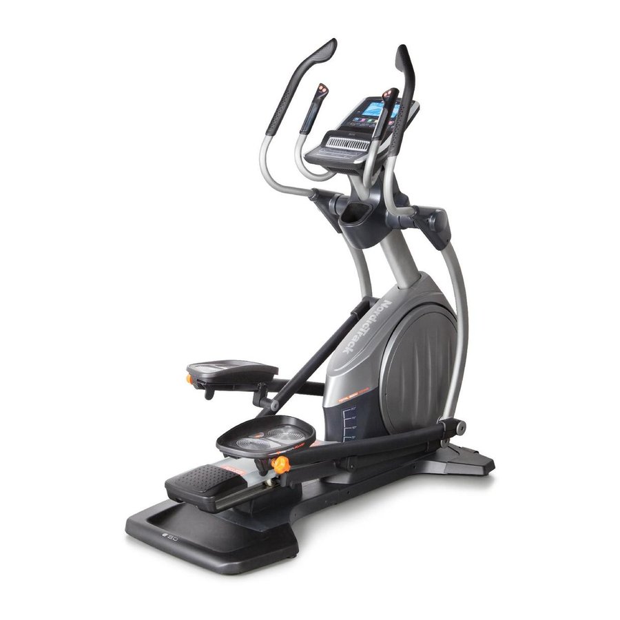
www.nordictrack.com
Model No. NTEL01011.1
USER'S MANUAL
Serial No.
Write the serial number in the space
above for reference.
Serial Number
Decal
QUESTIONS?
If you have questions, or if parts
are damaged or missing, DO NOT
CONTACT THE STORE; please
contact Customer Care.
IMPORTANT: Please register this
product (see the limited warranty
on the back cover of this manual)
before contacting Customer Care.
CALL TOLL-FREE:
1-800-TO-BE-FIT
(1-800- 862-3348)
Mon.–Fri., 6 a.m.–6 p.m. MT
Sat. 8 a.m.–4 p.m. MT
ON THE WEB:
www.nordictrackservice.com
CAUTION
Read all precautions and instruc-
tions in this manual before using
this equipment. Keep this manual
for future reference.
Advertisement
Table of Contents

Subscribe to Our Youtube Channel
Related Manuals for NordicTrack E 9.0 Elliptical


Summary of Contents for NordicTrack E 9.0 Elliptical
- Page 1 Model No. NTEL01011.1 USER’S MANUAL Serial No. Write the serial number in the space above for reference. Serial Number Decal QUESTIONS? If you have questions, or if parts are damaged or missing, DO NOT CONTACT THE STORE; please contact Customer Care.
-
Page 2: Table Of Contents
Apply the decal in the location shown. Note: The decal(s) may not be shown at actual size. NORDICTRACK is a registered trademark of ICON IP, Inc. -
Page 3: Important Precautions
IMPORTANT PRECAUTIONS WARNING: To reduce the risk of serious injury, read all important precautions and instructions in this manual and all warnings on your elliptical before using your elliptical. ICON assumes no responsibility for personal injury or property damage sustained by or through the use of this product. -
Page 4: Before You Begin
NORDICTRACK ® E 9.0 elliptical. The E 9.0 elliptical manual. To help us assist you, note the product model provides an impressive selection of features designed number and serial number before contacting us. The... -
Page 5: Part Identification Chart
PART IDENTIFICATION CHART Use the drawings below to identify the small parts needed for assembly. The number in parentheses below each drawing is the key number of the part, from the PART LIST near the end of this manual. The number following the key number is the quantity needed for assembly. -
Page 6: Assembly
ASSEMBLY • Assembly requires two persons. • In addition to the included tool(s), assembly requires the following tools: • Place all parts in a cleared area and remove the one Phillips screwdriver packing materials. Do not dispose of the packing materials until you complete all assembly steps. - Page 7 3. Remove the screws (not shown) and the ship- ping bracket (not shown) from the rear of the Frame (1). Discard the screws. With the help of a second person, place the ship- ping bracket (not shown) under the rear of the Frame (1).
- Page 8 6. Tip: Avoid pinching the Main Wire (110). Set the Upright (4) on the Frame (1). Attach the Upright (4) with four M8 x 19mm Screws (82) and four M8 Star Washers (122). Avoid pinching the Main Wire (110) 7. Orient the Lower Upright Cover (56) as shown. Press the Lower Upright Cover (56) into the Shield Cover (75).
- Page 9 8. Identify the Left and Right Inner Covers (55, 68), which are marked with “Left” and “Right” stick- ers, and orient them as shown. Slide the Left Inner Cover (55) onto the left side of the Upright (4). Then, slide the Right Inner Cover (68) onto the right side of the Upright.
- Page 10 10. Tighten an M8 x 16mm Screw (120) and an M8 x 25mm Washer (98) into each end of the Pivot Axle (35) at the same time. 11. Identify the Right Pedal (49) and the Right Pedal Arm (58), which are marked with “Right” stickers, and orient them as shown.
- Page 11 12. Orient the Left Pedal Arm (44) as shown. Apply grease to the axle on the Left Pedal Arm (44). Attach the Left Pedal Arm (44) to the Left Roller Arm (12) with an M8 x 16mm Screw (120), a Roller Arm Cover (81), and an M8 x 25mm Grease Washer (98).
- Page 12 14. Insert the Right Upper Body Arm (61) into the Right Upper Body Leg (36). Attach the Right Upper Body Arm (61) with two M8 x 35mm Bolts (96) and two M8 Locknuts (102). Make sure that the Locknuts are in the hexagonal holes.
- Page 13 16. Untie and discard the wire tie on the Main Wire (110). While a second person holds the Console (7) near the Upright (4), connect the wires on the Console to the Main Wire (110) and to the Right and Left Sensor Wires (63, 69). 63, 69 Insert the excess wire into the Upright (4) or into the Console (7).
- Page 14 19. Orient the Front Upright Cover (91) as shown. Press the Front Upright Cover (91) into the Rear Upright Cover (80). Attach the Front Upright Cover (91) to the Upright (4) with a #8 x 3/4" Screw (123). 20. Make sure that all parts are properly tightened before you use the elliptical. Note: After assembly is com- pleted, some extra parts may be left over.
-
Page 15: How To Use The Heart Rate Monitor
THE CHEST HEART RATE MONITOR HOW TO PUT ON THE HEART RATE MONITOR • Do not expose the heart rate monitor to direct sun- light for extended periods of time; do not expose it to The heart rate temperatures above 122° F (50° C) or below 14° F monitor consists of (-10°... -
Page 16: How To Use The Elliptical
HOW TO USE THE ELLIPTICAL HOW TO PLUG IN THE POWER CORD HOW TO MOVE THE ELLIPTICAL This product must be grounded. If it should mal- Due to the size and weight of the elliptical, moving function or break down, grounding provides a path of it requires two persons. - Page 17 HOW TO ADJUST THE POSITIONS OF THE HOW TO EXERCISE ON THE ELLIPTICAL PEDALS To mount the elliptical, hold the upper body arms or Each pedal can be adjusted to several positions. To the handlebars and step onto the pedal that is in the adjust each pedal, simply lift the pedal and turn the lower position.
-
Page 18: Console Diagram/Features Of The Console
CONSOLE DIAGRAM FEATURES OF THE CONSOLE The advanced console offers an array of features designed to make your workouts more effective and enjoyable. When you use the manual mode of the console, you can change the resistance of the pedals and the incline of the ramp with the touch of a button. - Page 19 HOW TO TURN ON THE POWER HOW TO USE THE MANUAL MODE IMPORTANT: If the elliptical has been exposed to 1. Begin pedaling or press any button on the cold temperatures, allow it to warm to room tem- console to turn on the console. perature before turning on the power.
- Page 20 4. Follow your progress with the display. Stride—This display mode will show the total num- ber of strides you have pedaled. The display can show the following workout information: Time—When the manual mode is selected, this display mode will show the elapsed time. When a workout is selected, this display mode will show the time remaining in the workout.
- Page 21 When a wireless iFit When your pulse is detected, a heart symbol in will Live module is con- flash in the display each time your heart beats, one nected, the wireless or two dashes will appear, and then your heart rate symbol at the top will be shown.
- Page 22 HOW TO USE A TARGET TONING WORKOUT At the end of each segment of the workout, a series of tones will sound and the next segment of 1. Begin pedaling or press any button on the the profile will begin to flash. If a different resis- console to turn on the console.
-
Page 23: To Use An Ifit Live Workout
HOW TO USE AN IFIT LIVE WORKOUT 5. Select an iFit Live workout. You must have an iFit Live module to use an iFit Live To select an iFit Live workout, press one of the workout. iFit Live buttons. Note: Before some workouts will download, you must go to www.iFit.com and add To purchase an iFit Live module at any time, go to them to your schedule. -
Page 24: To Use The Sound System
7. Follow your progress with the display. HOW TO USE THE SOUND SYSTEM See step 4 on page 20. To play music or audio books through the console sound system while you exercise, plug the included The My Trail tab will show a map of the trail you are audio cable into the jack on the console and into a jack walking or running or it will show a track and the on your MP3 player or CD player;... -
Page 25: To Change Console Settings
HOW TO CHANGE CONSOLE SETTINGS 6. Select an audio setting for the voice of the personal trainer if desired. The console features a user mode that allows you to view usage information, select a unit of measurement, Press the decrease button to view the audio setting and adjust the contrast level of the display. -
Page 26: Fcc Information
FCC INFORMATION This equipment has been tested and found to comply with the limits for a Class B digital device, pursuant to part 15 of the FCC Rules. These limits are designed to provide reasonable protection against harmful interference in a residential installation. This equipment generates, uses, and can radiate radio frequency energy and, if not installed and used in accordance with the instructions, may cause harmful interference to radio communications. -
Page 27: Maintenance And Troubleshooting
MAINTENANCE AND TROUBLESHOOTING Inspect and tighten all parts of the elliptical regularly. HOW TO ADJUST THE DRIVE BELT Replace any worn parts immediately. If the pedals slip while you are pedaling, even while To clean the elliptical, use a damp cloth and a small the resistance is adjusted to the highest level, the drive amount of mild soap. -
Page 28: To Adjust The Reed Switch
Loosen the M6 x HOW TO ADJUST THE REED SWITCH 12mm Hex Screw (85) and the M10 x 58mm If the console does not display correct feedback, the Hex Bolt (86). Then, reed switch should be adjusted. remove the right Crank Arm (20). -
Page 29: Exercise Guidelines
EXERCISE GUIDELINES Burning Fat—To burn fat effectively, you must exer- WARNING: cise at a low intensity level for a sustained period of Before beginning this time. During the first few minutes of exercise, your or any exercise program, consult your physi- body uses carbohydrate calories for energy. -
Page 30: Part List
PART LIST Model No. NTEL01011.1 R1011A Key No. Qty. Description Key No. Qty. Description Frame Roller Rear Stabilizer Cover Pedal Arm Cap Ramp Axle Cover Upright Left Outer Cover Rear Stabilizer Left Inner Cover Front Stabilizer Lower Upright Cover Console Roller Arm Bushing Front Stabilizer Cover Right Pedal Arm... - Page 31 Key No. Qty. Description Key No. Qty. Description Idler Screw Chest Strap M8 Locknut 1" Grommet M3.5 x 12mm Flat Head Screw Crank Arm Bushing M4 x 16mm Screw Ramp Shield M8 x 16mm Hex Screw Roller Arm Flex Bracket M4 x 13mm Bright Screw Pedal Arm Flex Bracket Standoff...
-
Page 32: Exploded Drawing
EXPLODED DRAWING A Model No. NTEL01011.1 R1011A... - Page 33 EXPLODED DRAWING B Model No. NTEL01011.1 R1011A...
- Page 34 EXPLODED DRAWING C Model No. NTEL01011.1 R1011A...
- Page 35 EXPLODED DRAWING D Model No. NTEL01011.1 R1011A...
-
Page 36: Ordering Replacement Parts
ORDERING REPLACEMENT PARTS To order replacement parts, please see the front cover of this manual. To help us assist you, be prepared to provide the following information when contacting us: • the model number and serial number of the product (see the front cover of this manual) •...
Need help?
Do you have a question about the E 9.0 Elliptical and is the answer not in the manual?
Questions and answers
How to tighten handles that come loose