Moxa Technologies EtherDevice EDS-518A Series Hardware Installation Manual
Hide thumbs
Also See for EtherDevice EDS-518A Series:
- User manual (97 pages) ,
- Hardware installation manual (17 pages) ,
- Manual (84 pages)
Table of Contents
Advertisement
Quick Links
Advertisement
Table of Contents

Related Manuals for Moxa Technologies EtherDevice EDS-518A Series


Summary of Contents for Moxa Technologies EtherDevice EDS-518A Series
- Page 1 Moxa EtherDevice™ Switch EDS-518A Series Hardware Installation Guide Fifth Edition, June 2010 © 2010 Moxa Inc. All rights reserved. Reproduction without permission is prohibited. Fl.4, No.135, Lane 235, Pao-Chiao Rd. Shing Tien City, Taipei, Taiwan, R.O.C. TEL: +886-2-8919-1230 P/N: 1802005180013...
-
Page 2: Package Checklist
Package Checklist Moxa EtherDevice™ Switch is shipped with the following items. If any of these items are missing or damaged, please contact your customer service representative for assistance. 1 Moxa EtherDevice Switch EDS-518A Hardware Installation Guide CD-ROM with User’s Manual and Windows Utility Moxa Product Warranty Booklet RJ45 to DB9 Console port cable Protective caps for unused ports... - Page 3 Panel Views of EDS-518A Grounding screw Console port Heat dissipation orifices 6-pin terminal block for DI 1, DI 2, and PWR 2 6-pin terminal block for PWR1 Relay 1, and Relay 2 10/100BaseT(X), ports 1 to 16 PWR 1: LED for power input 1 PWR 2: LED for power input 2 Fault LED 10.
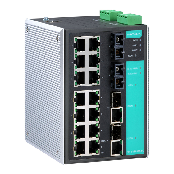
- Page 4 Panel Views of EDS-518A (SC/ST Type) NOTE: The appearance of EDS-518A-SS-SC is identical to EDS-518A-MM-SC. The appearance of EDS-518A-MM-ST is identical to EDS-518A-MM-SC. Grounding screw Console port Heat dissipation orifices 6-pin terminal block for DI 1, DI 2, and PWR 2 6-pin terminal block for PWR1 Relay 1, and Relay 2 10/100BaseT(X), ports 1 to 14...
-
Page 5: Mounting Dimensions (Unit = Mm)
Mounting Dimensions (unit = mm) 30.00 15.00 13.4 36.91 71.01 0.79 PWR1 PWR2 DlN-Rail FAULT 100M MSTR/HEAD CPLR/TAIL 100M 1000M DlN-Rail Kit 1000M 100M EDS-518A-MM-SC Front View 127.52 Side View 18.2 13.9 13.9 DlN-Rail Kit 30.50 86.80 7.75 7.75 Rear View Wall Mounting Kit DIN-Rail Mounting The aluminum DIN-Rail attachment plate should already be fixed to the back... -
Page 6: Wall Mounting (Optional)
Wall Mounting (Optional) For some applications, you will find it convenient to mount Moxa EDS-518A on the wall, as shown by the following illustrations: STEP 1—Remove the aluminum DIN-Rail attachment plate from the Moxa EDS-518A rear panel, plate and then attach the wall mount plates with M3 screws, as shown by the figure on the Bottom... -
Page 7: Atex Information
II 3G ATEX Information 1. Certification number DEMKO 09 ATEX 0812123X 2. Ambient range (-40°C ≤ Tamb ≤ 75°C) 3. Certification string (Ex nC IIC T4) 4. Standards covered ( EN60079-0:2006, EN60079-15:2005) 5. The conditions of safe usage: The Ethernet Communication Devices are to be mounted in an IP54 enclosure and used in an area of not more than pollution degree 2 as defined by IEC60664-1. -
Page 8: Wiring The Relay Contact
You should also pay attention to the following points: Use separate paths to route wiring for power and devices. If power wiring and device wiring paths must cross, make sure the wires are perpendicular at the intersection point NOTE: Do not run signal or communications wiring and power wiring through the same wire conduit. -
Page 9: Wiring The Digital Inputs
STEP 1: Insert the negative/positive DC wires into V1- V1+ V2- V2+ the V-/V+ terminals, respectively. STEP 2: To keep the DC wires from pulling loose, use a small flat-blade screwdriver to tighten PWR2 PWR1 the wire-clamp screws on the front of the terminal block connector. -
Page 10: Pin Description
The information to the left of the left vertical dashed lines gives the pinouts of the relevant Moxa EtherDevice Switch port. The information to the right of the right vertical dashed line gives the pinouts of the opposing device’s port. NOTE The pin numbers for male DB9 and DB25 connectors, and hole numbers for female DB9 and DB25 connectors are... - Page 11 RJ45 (10-pin) to DB25 (F) Cable Wiring Moxa COM Port EtherDevice Server RJ45 Plug Pin 1 RJ45 Female DB25 Connector Cable Wiring Connector 10/100BaseT(X) Ethernet Port Connection The 10/100BaseT(X) ports located on Moxa EtherDevice Switch’s front panel are used to connect to Ethernet-enabled devices. Most users will choose to configure these ports for Auto MDI/MDI-X mode, in which case the port’s pinouts are adjusted automatically depending on the type of Ethernet cable used (straight-through or cross-over), and the type of device (NIC-type or...
-
Page 12: Cable Wiring
RJ45 (8-pin) to RJ45 (8-pin) Cross-over Cable Wiring Switch Port Cross-Over Cable Switch Port (NIC Port) (NIC Port) RJ45 Plug Pin 1 RJ45 RJ45 Connector Cable Wiring Connector (Rx+) (Tx+) (Rx-) (Tx-) (Tx+) (Rx+) (Tx-) (Rx-) 100BaseFx Ethernet Port Connection The concept behind the SC/ST port and cable is quite straightforward. -
Page 13: Led Indicators
LED Indicators The front panel of Moxa EDS-518A contains several LED indicators. The function of each LED is described in the following table: Color State Description Power is being supplied to power input P1. PWR1 AMBER Power is not being supplied to power input P1. -
Page 14: Specifications
TP/SFP port’s 1000 Mbps link is active. 1000M Data is being transmitted at 1000 GREEN Blinking (TP/SFP) Mbps. TP/SFP port’s 1000 Mbps link is inactive. Specifications Technology Standards IEEE 802.3 for 10BaseT, IEEE 802.3u for 100BaseT(X) and 100Base FX, IEEE 802.3ab for 1000BaseT(X), IEEE 802.3z for 1000BaseSX/LX/LHX/ZX, IEEE 802.3x for Flow Control, IEEE 802.1D for Spanning Tree Protocol,... - Page 15 Wavelength 850 nm 1310 nm 1310 nm 1310 nm Max. Tx -4 dBm -3 dBm 1 dBm +5 dBm Min. Tx -9.5 dBm -9.5 dBm -4 dBm 0 dBm Rx Sensitivity -18 dBm -20 dBm -24 dBm -24 dBm Link Budget 8.5 dB 10.5 dB 20 dB...
- Page 16 Casing IP30 protection, metal case 95 × 135 × 140 mm (W × H × D) Dimensions Weight 1.63 kg Installation DIN-Rail, Wall Mounting (optional kit) Environment Operating Temperature 0 to 60°C (32 to 140°F), -40 to 75°C (-40 to 167°F) for –T models Storage Temperature -40 to 85°C (-40 to 185°F) Ambient Relative...
Need help?
Do you have a question about the EtherDevice EDS-518A Series and is the answer not in the manual?
Questions and answers