Table of Contents
Advertisement
Quick Links
Advertisement
Table of Contents

Related Manuals for AudioArts Engineering audio console r-55e


Summary of Contents for AudioArts Engineering audio console r-55e
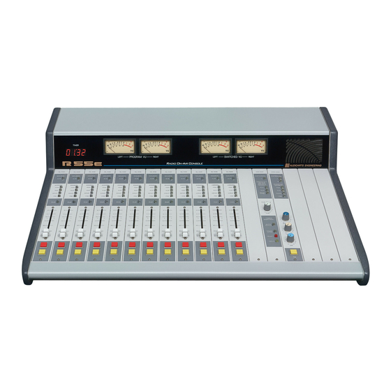
- Page 1 R-55e Audio Console ECHNICAL ANUAL July 2004...
- Page 2 R-55e Audio Console Technical Manual - 1st Edition R-55e Audio Console Technical Manual - 1st Edition ® ©2004 Audioarts Engineering* AUDIOARTS ENGINEERING 600 Industrial Drive New Bern, North Carolina 28562 252-638-7000 *a division of Wheatstone Corporation R-55e / July 2004...
- Page 3 A A A A A T T E N T I O N T T E N T I O N T T E N T I O N T T E N T I O N T T E N T I O N Attention! F F F F F ederal Communications Commission (FCC) Compliance ederal Communications Commission (FCC) Compliance...
-
Page 4: Table Of Contents
C O N T E N T S R-55e Technical Manual Table of Contents Chapter 1 – Installation Unpacking the Console ............. 1-2 Countertop Mounting ..............1-2 System Ground ................1-3 Power Supply ................1-5 Failsafe Dual Redundant Supply ................1-6 Energizing ....................... - Page 5 C O N T E N T S Chapter 3 - Stereo Line Input (SL-55e) Module Overview ................3-2 Internal Programming Options ............3-3 Mutes ........................3-3 Timer Restart ......................3-3 Local/Ready ......................3-3 Talkback ........................3-3 Hook-ups ..................3-4 ANALOG AUDIO CONNECTIONS ................3-4 CONTROL CONNECTIONS ..................
- Page 6 C O N T E N T S Chapter 6 - Second Studio Module (SS-55e) - optional Module Overview ................6-2 Internal Programming Options ............6-3 Cue Interrupt ......................6-3 HDPN 3 Mute ......................6-3 Studio 2 Mute ......................6-3 Studio 2 Dim ......................6-3 Hook-ups ..................6-4 Left DB-25 “A”...
- Page 7 C O N T E N T S Chapter 10 - Meterbridge Overview ................... 10-2 Digital Timer ................10-2 Digital Clock ................10-3 Controls ......................... 10-3 Setting the Time ....................10-3 Capacitor Backup ....................10-3 Operational Modes ....................10-3 Chapter 11 - Parts List QMP-4 Quad Mic Preamp ..................
- Page 8 C O N T E N T S Output Master (OM-55e) schematic ......................12-9 load sheet drawing ....................12-12 Control Room/Studio (CRS-55e) & Second Studio (SS-55e) schematic ......................12-13 load sheet drawing ....................12-16 Superphone (SPN-55e) schematic ......................12-17 load sheet drawing ....................12-20 Line Select (LS-55e) schematic ......................
- Page 9 I N S T A L L A T I O N a n d P O W E R Installation and Power Chapter Contents Unpacking the Console ............. 1-2 Countertop Mounting ..............1-2 System Ground ................1-3 Power Supply ................1-5 Failsafe Dual Redundant Supply ................
-
Page 10: Unpacking The Console
I N S T A L L A T I O N a n d P O W E R Installation and Power Unpacking the Console The R-55e console is shipped as two packages. One (larger) carton contains the console and technical documentation; and the other (smaller) contains the rackmount power supply, connecting cable, and connector kit. -
Page 11: System Ground
I N S T A L L A T I O N a n d P O W E R System Ground The first step is to ground the console. Note that as supplied from the factory, console rackmount power supply common, audio ground, and the R-55e mainframe are con- nected together at the console, but are NOT connected to electrical ground and the chassis of the power supply. - Page 12 I N S T A L L A T I O N a n d P O W E R (B) THE POWER COMPANY EARTH CONDUCTOR that enters the build- ing at the power line breaker box; this conductor should be (and is often by code) tied to the above-mentioned earth ground at one point.
-
Page 13: Power Supply
I N S T A L L A T I O N A N D P O W E R Power Supply Front view of the SPS-100 rackmount power supply Rear view of the SPS-100 rackmount power supply The R-55e console is powered by an Audioarts Model SPS-100 If failsafe redundant sup- rackmount power supply. -
Page 14: Failsafe Dual Redundant Supply
I N S T A L L A T I O N a n d P O W E R The power feed recom- Note that each power supply is fitted with a 3-wire grounded AC mended in the text is of- cord that should be plugged into a "clean"... -
Page 15: Audio And Control Wiring
I N S T A L L A T I O N a n d P O W E R Audio and Control Wiring All audio and control I/O connections to the R-55e console are made through multipin DB-25 connectors located on the top of each module. The output module also has a DB-9 connector. -
Page 16: Hand Crimp Tool Wiring Instructions
I N S T A L L A T I O N a n d P O W E R HAND CRIMP TOOL WIRING INSTRUCTIONS The supplied hand crimping tool (W/S#850067) is used for all I/O wiring con- nections to and from the console. It is to be used with the supplied pin (figure 1) intended for 22"-28"... - Page 17 I N S T A L L A T I O N a n d P O W E R EXTRACTOR PIN INSTRUCTIONS If you accidentally insert a crimp terminal pin into the wrong socket, you'll need to use the supplied pin extractor tool (W/S#850069) to remove terminal pin, and correct your mis- take without having to sacrifice a connector.
-
Page 18: Wiring Procedure - Double Connection To One Pin
I N S T A L L A T I O N a n d P O W E R Wiring Procedure - Double Connection to One Pin ref: DB-25 male multi-pin connector Most audio equipment machine interfaces (as well as Wheatstone consoles) use subminiature D-type connectors. -
Page 19: R-55E 12-Position Frame - Modules Layout
NOTE: 1. CONSOLE CAN ACCOMMODATE UP TO 9 INPUT AND ACCESSORY MODULES (OPTIONAL MODULES— SUPERPHONE, LINE SELECT, AND TAPE REMOTE—CAN BE PLACED IN ANY SLOT POS. 1-9). 2. MASTER OUTPUT, CONTROL ROOM, AND OPTIONAL SECOND STUDIO MODULES HAVE THEIR DEDICATED SLOTS (AS SHOWN). 4. -
Page 20: R-55E 18-Position Frame - Modules Layout
NOTE: 1. CONSOLE CAN ACCOMMODATE UP TO 13 INPUT MODULES AND ACCESSORY MODULES (OPTIONAL MODULES—SUPERPHONE, LINE SELECT, AND TAPE REMOTE—CAN BE PLACED IN ANY SLOT POS. 1-13). 2. MASTER OUTPUT, CONTROL ROOM, AND OPTIONAL SECOND STUDIO MODULES HAVE THEIR DEDICATED SLOTS (AS SHOWN). 3. -
Page 21: R-55E 26-Position Frame - Modules Layout
NOTE: 1. CONSOLE CAN ACCOMMODATE UP TO 21 INPUT AND ACCESSORY MODULES (OPTIONAL MODULES—SUPERPHONE, LINE SELECT, AND TAPE REMOTE—CAN BE PLACED IN ANY SLOT POS. 1-21). 2. MASTER OUTPUT, CONTROL ROOM, AND OPTIONAL SECOND STUDIO MODULES HAVE THEIR DEDICATED SLOTS (AS SHOWN). 3. - Page 22 Q U A D M I C P R E A M P Quad Mic Preamp (QMP-4) Chapter Contents Overview ..................2-2 Internal Programming Options ..........2-3 Phantom Power ...................... 2-3 Hook-ups ..................2-3 AUDIO INPUT CONNECTIONS ................2-3 AUDIO OUTPUT CONNECTIONS ................. 2-4 POWER CONNECTIONS ..................
-
Page 23: Chapter 2 - Quad Mic Preamp (Qmp-4)
Q U A D M I C P R E A M P Quad Mic Preamp (QMP-4) Overview The QMP-4 is a quad mono microphone preamplifier and is mounted in the left side of the console meterbridge rear. Mic level sources are wired to QMP-4 mic preamp inputs. -
Page 24: Internal Programming Options
Q U A D M I C P R E A M P Recessed meterbridge rear trimpots (range 38dB) adjust the level of each input independently. Mic 1 Example: with a microphone input of –60dBm @150Ω at the port, gain trim can set Mic 2 levels from -22dBu to +16dBu (note maximum preamp gain is +76dB). -
Page 25: Audio Output Connections
Q U A D M I C P R E A M P Pin 7 – Mic 3 In SH Pin 8 – Mic 3 In LO Pin 9 – Mic 3 In HI Pin 10 – Mic 4 In SH Pin 11 –... -
Page 26: Power Connections
Q U A D M I C P R E A M P Power Connections (CT7) A ribbon cable connects the 10-pin connector on the QMP-4 (CT7) to the 10-pin connector mounted on the center of the MBR-2000 motherboard (CT8) or MBR-55 motherboard (CT18) to provide power to the microphone preamplifier. - Page 27 Q U A D M I C P R E A M P QMP-4 Quad Mic Preamp Plug Terminal Pinouts MIC 1 IN SH MIC 1 IN LO MIC 1 IN HI MIC 2 IN SH MIC 2 IN LO INPUT PORTS MIC 2 IN HI...
-
Page 28: Installing The Optional Second Qmp-4 Mic Preamp
Q U A D M I C P R E A M P Installing the Optional Second QMP-4 Mic Preamp Optional QMP-4 Area Connector The optional second QMP-4 comes complete with mounting hardware. The ribbon cable, installed at the factory to provide power to the pre-installed QMP-4 card, also includes a second plug (“Connector”... - Page 29 S T E R E O L I N E I N P U T Stereo Line Input (SL-55e) Chapter Contents Module Overview ................ 3-2 Internal Programming Options ..........3-3 Mutes ........................3-3 Timer Restart ......................3-3 Local/Ready ......................3-3 Talkback ........................
-
Page 30: Module Overview
S T E R E O L I N E I N P U T Stereo Line Input (SL-55e) Module Overview SL-55e modules are for stereo line input signals. Each module accepts two stereo sources: A and B, switched at the top of the module. -
Page 31: Internal Programming Options
S T E R E O L I N E I N P U T Internal Programming Options All internal programming is made via PCB mounted dipswitch SW1 located on the top of the module (beneath the DB-25 connector). Note that when a dipswitch position is thrown to the right it is ON. -
Page 32: Hook-Ups
S T E R E O L I N E I N P U T between the module’s DB-25 connector “TB to CR” control pin (DB-25 pin 17) and Digital Ground (DB-25 pin 19). As long as this closure is maintained (i.e., as long as talent holds down the studio TB button) the module’s (pre-fader, pre-on/off) signal will be placed on the console’s Cue bus. - Page 33 S T E R E O L I N E I N P U T To Turn the Module ON & OFF from a Remote Location In the case of stereo line input modules, “remote location” can also refer to a remote source machine that is feeding its audio to the module in question.
- Page 34 S T E R E O L I N E I N P U T On Tally Lets the module’s channel ON switch control an on-air light or other “microphone on” indicator at a remote location. This control function provides a continuous +5 volt signal at Pin 15 (On Tally) whenever the module is ON.
-
Page 35: Remote On & Off
S T E R E O L I N E I N P U T SL-55e Stereo Line Input DB Connector Pinouts AUDIO GROUND LINE A LT IN SH LINE A LT IN LO LINE A LT IN HI LINE A RT IN SH LINE A RT IN LO LINE A RT IN HI LINE B LT IN SH... -
Page 36: Db Connector Pinout Drawing
O U T P U T M O D U L E Output Module (OM-55e) Chapter Contents Module Overview ................ 4-2 Hook-ups ..................4-3 DB-25 Connector — AUDIO ................... 4-3 DB-9 Connector — AUDIO ..................4-3 DB-9 Connector — CONTROL ................4-4 DB Connector Pinout Drawing .......... -
Page 37: Module Overview
O U T P U T M O D U L E Output Module (OM-55e) Module Overview The master output module handles the console’s Program, Audi- tion, and Mono/Mix-Minus outputs. All outputs are calibrated with recessed front panel multi-turn trimpots. The R-55e console has two pairs of left-right VU meters, PGM and SWT (switched), except for the R-55e-8 (12 position frame), which has only the SWT meter pair. -
Page 38: Hook-Ups
O U T P U T M O D U L E Hook-Ups As stated before, all user wiring to and from the OM-55e modules takes place at DB-25 and DB-9 multi-pin connectors on the top of module. DB-25 Connector – Audio Handles External input and Program, Audition, Mono, and Pre outputs. -
Page 39: Db-9 Connector - Control
O U T P U T M O D U L E DB-9 Connector — Control Handles Tally 1 and Tally 2 control connections. Pin 3 – Tally 1 N.O. Pin 7 – Tally 1 Com Pin 6 – Tally 2 Com Pin 1 –... - Page 40 O U T P U T M O D U L E OM-55e Output Module DB Connector Pinouts AUDIO GROUND PGM LT OUT SH PGM LT OUT LO PGM LT OUT HI PGM RT OUT SH PGM RT OUT LO PGM RT OUT HI AUD LT OUT SH AUD LT OUT LO...
-
Page 41: Db Connector Pinout Drawing
C O N T R O L R O O M M O D U L E Control Room/Studio Module (CRS-55e) Chapter Contents Module Overview ................ 5-2 Internal Programming Options ..........5-3 Cue Interrupt ......................5-3 CR/Cue Mute ......................5-3 Studio Mute ...................... -
Page 42: Module Overview
C O N T R O L R O O M M O D U L E Control Room/Studio Module (CRS-55e) Module Overview The CRS-55e module is the R-55e console operator’s monitor module. It allows the operator to listen to the console’s two stereo (PGM & AUD) outputs, two mono (MONO &... -
Page 43: Internal Programming Options
C O N T R O L R O O M M O D U L E Internal Programming Options Internal programming for the control room/studio module is made via printed circuit board (PCB) mounted dipswitch SW1 located on the top of the module (beneath the DB-25 connectors). -
Page 44: Hook-Ups
C O N T R O L R O O M M O D U L E Hook-Ups As stated before, all user wiring to and from the CRS-55e module takes place at the two DB-25 multi-pin connectors mounted at the top of the module. - Page 45 C O N T R O L R O O M M O D U L E Pin 22 – ST Lt Out SH Pin 21 – ST Lt Out HI Pin 9 – ST Lt Out LO Pin 8 – ST Rt Out SH Pin 7 –...
- Page 46 C O N T R O L R O O M M O D U L E CRS-55e Control Room/Studio Module DB Connector Pinouts AUDIO GROUND EXT 2 LT IN SH EXT 2 LT IN LO EXT 2 LT IN HI EXT 2 RT IN SH EXT 2 RT IN LO EXT 2 RT IN HI...
-
Page 47: Db Connector Pinout Drawing
S E C O N D S T U D I O M O D U L E Second Studio Module (SS-55e; optional) Chapter Contents Module Overview ................ 6-2 Internal Programming Options ..........6-3 Cue Interrupt ......................6-3 HDPN 3 Mute ......................6-3 Studio 2 Mute ...................... -
Page 48: Module Overview
S E C O N D S T U D I O M O D U L E Second Studio Module (SS-55e; optional) Module Overview The optional SS-55e module is similar to the CRS-55e module. The monitor signal being sent to this studio follows the source select switching. This switching is indentical to the control room/monitor module’s and includes the console’s two stereo (PGM &... -
Page 49: Internal Programming Options
S E C O N D S T U D I O M O D U L E Internal Programming Options Internal programming for the control room/studio module is made via printed circuit board (PCB) mounted dipswitch SW1 located on the top of the module (beneath the DB-25 connectors). -
Page 50: Hook-Ups
S E C O N D S T U D I O M O D U L E Hook-Ups As stated before, all user wiring to and from the SS-55e module takes place at the two DB-25 multi-pin connectors mounted at the top of the module. - Page 51 S E C O N D S T U D I O M O D U L E Pin 22 – ST 2 Lt Out SH Pin 21 – ST 2 Lt Out HI Pin 9 – ST 2 Lt Out LO Pin 8 –...
- Page 52 S E C O N D S T U D I O M O D U L E SS-55e Second Studio Module DB Connector Pinouts AUDIO GROUND EXT 2 LT IN SH EXT 2 LT IN LO EXT 2 LT IN HI EXT 2 RT IN SH EXT 2 RT IN LO EXT 2 RT IN HI...
-
Page 53: External Start & Stop
S U P E R P H O N E I N P U T Superphone Input (SPN-55e; optional) Chapter Contents Module Overview ................ 7-2 Caller Set-Ups ......................7-2 Internal Programming Options ..........7-3 Mutes ........................7-3 Timer Restart ......................7-3 Gain Trimpot ...................... -
Page 54: Module Overview
S U P E R P H O N E I N P U T Superphone Input (SPN-55e; optional) Module Overview The SPN-55e input module is used for telephone call-ins. Caller signals enter the module from your station hybrid. The long-throw fader controls the level of the caller’s voice. -
Page 55: Internal Programming Options
S U P E R P H O N E I N P U T Internal Programming Options Internal programming is accomplished via printed circuit board (PCB) mounted dipswitch SW1, located on the top of the module (beneath the DB-25 connector). Note when a dipswitch position is thrown to the right it is ON. - Page 56 S U P E R P H O N E I N P U T Pin 14 – Remote On Pin 15 – ON Tally Pin 16 - Remote Off Pin 18 - +5V Digital Pin 19 - Digital Ground To Turn the Module ON &...
-
Page 57: Remote On & Off
S U P E R P H O N E I N P U T SPN-55e Superphone Module DB Connector Pinouts AUDIO GROUND CALL IN SH CALL IN LO CALL IN HI CALL OUT SH CALL OUT LO I/O PORTS CALL OUT HI ANALOG DIGITAL GROUND... - Page 58 L I N E S E L E C T M O D U L E Line Select Module (LS-55e; optional) Chapter Contents Module Overview ................. 8-2 Internal Programming Options ............8-2 Hook-ups ....................8-3 Left DB-25 “A” Connector — AUDIO INPUTS ..............8-3 Left DB-25 “A”...
-
Page 59: Module Overview
L I N E S E L E C T M O D U L E Line Select Module (LS-55e; optional) Module Overview This optional module selects one of six stereo line sources and routes it to one stereo output, allowing you to expand the source capability of an input channel or monitor module. -
Page 60: Hook-Ups
L I N E S E L E C T M O D U L E Hook-Ups Left DB-25 “A” Connector - Audio Inputs 5, 6 Pin 25 – Line 5 Lt In SH Pin 24 – Line 5 Lt In HI Pin 12 –... - Page 61 L I N E S E L E C T M O D U L E Pin 16 – Line 4 Lt In SH Pin 15 – Line 4 Lt In HI Pin 3 – Line 4 Lt In LO Pin 2 –...
- Page 62 L I N E S E L E C T M O D U L E LS-55e Line Selector Module DB Connector Pinouts LINE 5 LT IN SH LINE 5 LT IN LO LINE 5 LT IN HI LINE 5 RT IN SH LINE 5 RT IN LO LINE 5 RT IN HI LINE 6 LT IN SH...
-
Page 63: Chapter 9 - Tape Remote Module (Tr-55E) - Optional
T A P E R E M O T E M O D U L E Tape Remote Module (TR-55e; optional) Chapter Contents Module Overview ................9-2 DB Connector Pinout Drawings START/STOP Function Control I/O ................9-3 Full-Function Control I/O ..................9-4 page 9 –... - Page 64 T A P E R E M O T E M O D U L E Tape Remote Module (TR-55e; optional) Module Overview This optional module is available in two versions. The START/STOP version offers three sets of START and STOP buttons to provide start-stop control of three remote reel-to-reel machines.
- Page 65 T A P E R E M O T E M O D U L E TR-55e/SS Tape Remote Module DB Connector Pinouts SW6 (STOP) COMMON SW6 (STOP) N.O. SW6 (STOP) LED- SW6 (STOP) LED+ SW5 (START) COMMON SW5 (START) N.O. SW5 (START) LED- SW5 (START) LED+ SW4 (STOP) COMMON...
- Page 66 T A P E R E M O T E M O D U L E TR-55e/FF Tape Remote Module DB Connector Pinouts SW6 (PLAY) COMMON SW6 (PLAY) N.O. SW6 (PLAY) LED- SW6 (PLAY) LED+ SW5 (REC) COMMON SW5 (REC) N.O. SW5 (REC) LED- SW5 (REC) LED+ I/O CONTROL...
- Page 67 M E T E R B R I D G E Meterbridge Chapter Contents Overview ..................10-2 Digital Timer ................10-2 Digital Clock ................10-3 Controls ........................10-3 Setting the Time ....................... 10-3 Capacitor Backup ....................10-3 Operational Modes ....................10-4 page 10 –...
-
Page 68: Chapter 10 - Meterbridge
M E T E R B R I D G E Meterbridge Overview All three versions of the console’s meterbridge house left-right VU meters (see “Output Module” Chapter 4) and the cue speaker. The 18-position frame meterbridge also includes the digital timer display, and the 26-position frame meterbridge includes the digital timer display and the digital clock. -
Page 69: Setting The Time
M E T E R B R I D G E Digital Clock The Wheatstone digital clock is a six-digit time-of-day clock with LED display. The clock is designed with CMOS circuits and an on-board crystal- controlled time base oscillator. The clock PCB contains the clock circuits, clock set controls and capacitor backup on one side and displays on the other side. - Page 70 M E T E R B R I D G E The clock can also be synchronized to external 60Hz or 1Hz signals. To synchronize to a 60Hz signal, connect the signal to CT3 pin 1, using CT3 pin 2 as the ground reference, and enable synchronization to 60Hz by turning SW7 position 3 on (SW7 position 2 should be off).
- Page 71 P A R T S L I S T Parts List Chapter Contents QMP-4 Quad Mic Preamp ..................11-2 SL-55e Stereo Line Input ..................11-3 OM-55e Master Output .................... 11-5 CRS-55e Control Room/Studio ................11-7 SS-55e Second Studio (optional) ................11-10 SPN-55e Superphone Input (optional) ..............
- Page 72 QMP-4 QUAD MIC PREAMP PARTS LIST ITEM# DESCRIPTION U2, U4, U6, U8 8 PIN .3" DIP SMT SOCKET 245001 10PIN BOXED HEADER, STRAIGHT 250077 CT3, CT4 12 POSITION PLUG ON BARRIER STRIP 260045 CT3, CT4 12 POSITION BOXED HEADER RIGHT ANGLE 260057 U2, U4, U6, U8 2017 MIC PREAMP IC...
-
Page 73: Sl-55E Stereo Line Input
SL-55e STEREO LINE INPUT MODULE PARTS LIST ITEM# DESCRIPTION SL-55e FACEPLATE 005521 RIGHT ANGLE 25 PIN PC MOUNT CONNECTOR .318 220120 6 PIN .098" PLUG FOR #26 AWG 230031 9 PIN .098" PLUG FOR #26 AWG 230032 CT5, CT6 6 PIN .098" HEADER 250065 9 PIN .098"... - Page 74 SL-55e STEREO LINE INPUT MODULE PARTS LIST ITEM# DESCRIPTION DPDT PUSHBUTTON SWITCH, MOMENTARY ACTION, START/STOP SWITCH 510063 GRAY HOUSING SW2-SW7 2 POLE PUSHBUTTON SWITCH, ALTERNATE ACTION 510097 7 POSITION RIGHT ANGLE DIP SWITCH 510282 FADER KNOB WHITE FADER KNOB WITH BLACK LINE 520051 START SWITCH BUTTON LB STYLE RED BUTTON...
- Page 75 OM-55e OUTPUT MODULE PARTS LIST ITEM# DESCRIPTION OM-55e FACEPLATE 005536 THREADED 9 PIN DB CONNECTOR-IDD9 200031 RIGHT ANGLE 25 PIN PC MOUNT CONNECTOR .318 220120 10 PIN RIBBON PLUG 230020 3 PIN .O98” PLUG FOR #26 AWG 230028 3 PIN .098" HEADER 250062 10 PIN PC MOUNT STRAIGHT UP SMT HEADER 255005...
- Page 76 OM-55e OUTPUT MODULE PARTS LIST ITEM# DESCRIPTION R84-R87, R89, R94, R96-R98, R100-R102, 4.99 KOHM 1% .25W MC1206 RESISTOR 435023 R104-R106, R110, R112, R115, R117 R10, R13, R32, R35, R78 10.0 KOHM 1% .25W MC1206 RESISTOR 435028 R39, R40, R42, R43, R45, R47, R49, R50, R108 40.2 KOHM 1% .25W MC1206 RESISTOR 435039 88.7 KOHM 1% .25W MC1206 RESISTOR...
- Page 77 CRS-55e CONTROL ROOM/STUDIO MODULE PARTS LIST ITEM# DESCRIPTION CRS-55e FACEPLATE 005537 25 PIN DB CONNECTOR 200018 RIGHT ANGLE 25 PIN PC MOUNT CONNECTOR .318 220120 3 PIN .098" PLUG FOR #26 AWG 230028 6 PIN .098" PLUG FOR #26 AWG 230031 26 PIN RIBBON PLUG 250043...
- Page 78 CRS-55e CONTROL ROOM/STUDIO MODULE PARTS LIST ITEM# DESCRIPTION 332 OHM 1% .25W MC1206 RESISTOR 435010 R28, R30, R36, R38, R39 619 OHM 1% .25W MC1206 RESISTOR 435013 R123, R126, R128 1.00 KOHM 1% .25W MC1206 RESISTOR 435015 R32, R87, R98, R174, R194 1.69 KOHM 1% .25W MC1206 RESISTOR 435017 R40, R72, R188, R189...
- Page 79 CRS-55e CONTROL ROOM/STUDIO MODULE PARTS LIST ITEM# DESCRIPTION U20-U22 HEATSINK FOR T-220 WITH MOUNTING PIN 825010 F1, F5, F6 FUSE/ POLYSWITCH .17 AMP RESETABLE 830043 FUSE/ POLYSWITCH .3AMP SMT RESETABLE 835001 F2, F3 FUSE/ POLYSWITCH 1.0AMP SMT RESETABLE 835002 R-55e / July 2004 page 11 - 9...
- Page 80 SS-55e SECOND STUDIO MODULE PARTS LIST ITEM# DESCRIPTION SS-55e FACEPLATE 005538 25 PIN DB CONNECTOR 200018 RIGHT ANGLE 25 PIN PC MOUNT CONNECTOR .318 220120 3 PIN .098" PLUG FOR #26 AWG 230028 6 PIN .098" PLUG FOR #26 AWG 230031 26 PIN RIBBON PLUG 250043...
- Page 81 SS-55e SECOND STUDIO MODULE PARTS LIST ITEM# DESCRIPTION 332 OHM 1% .25W MC1206 RESISTOR 435010 R28, R30, R36, R38, R39 619 OHM 1% .25W MC1206 RESISTOR 435013 R123, R126, R128 1.00 KOHM 1% .25W MC1206 RESISTOR 435015 R32, R87, R98, R174, R194 1.69 KOHM 1% .25W MC1206 RESISTOR 435017 R188, R189...
- Page 82 SS-55e SECOND STUDIO MODULE PARTS LIST ITEM# DESCRIPTION U20, U21 HEATSINK FOR T-220 WITH MOUNTING PIN 825010 F1, F5, F6 FUSE/ POLYSWITCH .17 AMP RESETABLE 830043 FUSE/ POLYSWITCH .3AMP SMT RESETABLE 835001 F2, F3 FUSE/ POLYSWITCH 1.0AMP SMT RESETABLE 835002 R-55e / July 2004 page 11 - 12...
- Page 83 SPN-55e SUPERPHONE MODULE PARTS LIST ITEM# DESCRIPTION SPN-55e FACEPLATE 005523 RIGHT ANGLE 25 PIN PC MOUNT CONNECTOR .318 220120 6 PIN .098" PLUG FOR #26 AWG 230031 9 PIN .098" PLUG FOR #26 AWG 230032 CT6, CT7 6 PIN .098" HEADER 250065 9 PIN .098"...
- Page 84 SPN-55e SUPERPHONE MODULE PARTS LIST ITEM# DESCRIPTION DPDT PUSHBUTTON SWITCH, MOMENTARY ACTION, ON/OFF SWITCH 510063 GRAY HOUSING SW2-SW6 2 POLE PUSHBUTTON SWITCH, ALTERNATE ACTION 510097 7 POSITION RIGHT ANGLE DIP SWITCH 510282 FADER KNOB BLUE FADER KNOB WITH WHITE LINE 520052 ON SWITCH CAP LB STYLE RED BUTTON...
-
Page 85: Ls-55E Line Select
LS-55e LINE SELECT MODULE PARTS LIST ITEM# DESCRIPTION LS-55e FACEPLATE 005526 25 PIN DB CONNECTOR 200018 RIGHT ANGLE 25 PIN PC MOUNT CONNECTOR .318 220120 26 PIN PLUG 250043 26 PIN PC MOUNT STRAIGHT UP SMT HEADER 255003 R1-R12 10.0 KOHM 1% .25W MC1206 RESISTOR 435028 6 STATION 4 POLE INTERLOCKED SWITCH, 12.5MM SW1-SW6... -
Page 86: Tr-55E/Ff Tape Remote (Optional)
TR-55e/FF TAPE REMOTE MODULE PARTS LIST ITEM# DESCRIPTION TR-55e/FF FACEPLATE 005530 RIGHT ANGLE 25 PIN PC MOUNT CONNECTOR .318 220120 R1-R6 1.00 KOHM 1% .25W MC1206 RESISTOR 435015 SW1-SW6 2 POLE PUSHBUTTON SWITCH, MOMENTARY 510113 RTZ/FF/REW/STOP/REC/PLAY BUTTON CUSTOM WHITE LIGHT PIPE BUTTON 530083 DS1, DS3, DS5 ULTRABRIGHT RIGHT ANGLE RED SMT LED... -
Page 87: Tr-55E/Ss Tape Remote (Optional)
TR-55e/SS TAPE REMOTE MODULE PARTS LIST ITEM# DESCRIPTION TR-55e/SS FACEPLATE 005531 RIGHT ANGLE 25 PIN PC MOUNT CONNECTOR .318 220120 R1-R6 1.00 KOHM 1% .25W MC1206 RESISTOR 435015 SW1-SW6 2 POLE PUSHBUTTON SWITCH, MOMENTARY 510113 START/STOP BUTTON CUSTOM WHITE LIGHT PIPE BUTTON 530083 DS1, DS3, DS5 ULTRABRIGHT RIGHT ANGLE RED SMT LED... - Page 88 MBE-5508 MOTHER BOARD (EXTENDER) PARTS LIST ITEM# DESCRIPTION CT2-CT9 62 PIN PC MOUNT CARDEDGE CONNECTOR 220027 CT10 60 PIN BOARD-TO-BOARD MALE CONNECTOR 220074 60 PIN BOARD-TO-BOARD FEMALE CONNECTOR 220075 CAPACITOR, 10µF 63V ELECTROLYTIC 400012 C10, C11 CAPACITOR, 1µF 35V TANTALUM ORANGE 400014 C5, C8, C12, C14, C16 330UF 35V ELECTROLYTIC CAPACITOR...
-
Page 89: Mbr-2000 Mother Board
MBR-2000 MOTHER BOARD (RIGHT) PARTS LIST ITEM# DESCRIPTION CT2-CT5 62 PIN PC MOUNT CARDEDGE CONNECTOR 220027 60 PIN BOARD-TO-BOARD FEMALE CONNECTOR 220075 CT6, CT7, CT9, CT10 3 PIN .098" HEADER 250062 CT11 16PIN BOXED HEADER, STRAIGHT 250075 10PIN BOXED HEADER, STRAIGHT 250077 PCB_MBR2000 PRINTED CIRCUIT BOARD... - Page 90 MBR-5510 MOTHER BOARD (RIGHT) PARTS LIST ITEM# DESCRIPTION CT6-CT14, CT17 62 PIN PC MOUNT CARDEDGE CONNECTOR 220027 60 PIN BOARD-TO-BOARD FEMALE CONNECTOR 220075 CT15, CT19 3 PIN .098" HEADER 250062 CT21 16PIN BOXED HEADER, STRAIGHT 250075 CT2, CT22 10PIN BOXED HEADER, STRAIGHT 250077 CAPACITOR, 10µF 63V ELECTROLYTIC 400012...
- Page 91 CLK-55e CLOCK/TIMER PARTS LIST (for 26-pos. frame) ITEM# DESCRIPTION CT3-CT6 HEADER MTA 02 POS .1CC CHAIR 230064A 14 PIN .3" DIP SMT SOCKET 245002 DS1-DS11 20 POSITION SNAP APART SOCKET, .1" SIL 250014 40 PIN BREAKAWAY HEADER STRIPS, STRAIGHT .1" SIL 0.15 250016 10PIN BOXED HEADER, STRAIGHT...
- Page 92 CLK-55e CLOCK/TIMER PARTS LIST (for 26-pos. frame) ITEM# DESCRIPTION R5, R8, R10, R12, R14, R16, R19, R22, R87 332 OHM 1% 1/16W 0603 RESISTOR SMT 435070 R24, R26, R28, R30-R32, R35, R67, R74, R79, R81, 220Ω 5% 0603 SMT RESISTOR 435073 R86, R88 R72, R82...
- Page 93 TMR-55e TIMER PARTS LIST (for 18-pos. frame) ITEM# DESCRIPTION 14 PIN .3" DIP SMT SOCKET 245002 DS8-DS11 20 POSITION SNAP APART SOCKET, .1" SIL 250014 40 PIN BREAKAWAY HEADER STRIPS, STRAIGHT .1" SIL 0.15 250016 10PIN BOXED HEADER, STRAIGHT 250077 DS1706RESA TTL SMT 3.3V MicroMonitor 305054 DS1306E 32KHZ RTC SMT...
- Page 94 TMR-55e TIMER PARTS LIST (for 18-pos. frame) ITEM# DESCRIPTION R72, R82 88.7 KOHM 1% 1/16W 0603 RESISTOR SMT 435078 3.83KΩ 1% 0603 SMT RESISTOR 435081 4 POSITION SMT DIP SWITCH, TAPE SEALED 515001 DS12 HIGH INTENSITY RED SMT 0603 LED VERTICAL 605020 DS13 HIGH INTENSITY GREEN SMT 0603 LED VERTICAL...
-
Page 95: Power Supply
SPS-100 POWER SUPPLY PARTS LIST ITEM# DESCRIPTION SPS POWER SUPPLY CABLE 007222 PSU-1 FACE BRACKET 007328 SPS-100 COVER 007355 SPS-100 CHASSIS 007356 SPS-100 RACK FACE 007357 7 1/2' BLACK POWER CORD 150017 40 AMP RIGHT ANGLE PCB MOUNT SOCKET ROHS 200116 COMPLIANT 8 POSITION RECEPTACLE HOUSING... - Page 96 SPS-100 POWER SUPPLY PARTS LIST ITEM# DESCRIPTION CAPACITOR, 1uF 50V CERAMIC 1210 SMT ROHS C45, C46 415016 COMPLIANT C10-C13, C39-C42, C55 22UF 25V CERAMIC SMT CAPACITOR ROHS COMPLIANT 415018 C9, C38 10UF 50V CERAMIC SMT CAPACITOR ROHS COMPLIANT 415019 C31, C44, C56, C61 CAPACITOR, .47µF 250V METAL FILM ROHS COMPLIANT 420032 CAPACITOR, .1µF 400V SNUBER FILM ROHS COMPLIANT...
- Page 97 SPS-100 POWER SUPPLY PARTS LIST ITEM# DESCRIPTION 3/16 HEX 4-40 X 3/8" LONG BRASS/ZINC PLATE 823085 STANDOFF D3-D6 HEATSINK TO-220/T-3P DIODE ROHS COMPLIANT 825030 HEATSINK TO-220F5 CONTROLLER ROHS COMPLIANT 825032 F1, F2 PC MOUNT FUSE HOLDER 830014 F1, F2 SMALL 2 AMP FUSE 830015 FUSE/ POLYSWITCH 1.0AMP SMT RESETABLE 835002...
- Page 98 LED-3 METER LED LAMP PARTS LIST ITEM# DESCRIPTION Q1-Q5 MMBTA05 NPN SMT TRANSISTOR 345001 C1, C2 CAPACITOR, .1µF 50V CERAMIC SMT 415007 R2-R4, R7 3.3 OHM 5% .25W MC1206 RESISTOR 435001 R5, R6,R8, R9 39 OHM 5% .25W MC1206 RESISTOR 435004 1.00 KOHM 1% .25W MC1206 RESISTOR 435015...
-
Page 99: R-55E-18 (26-Pos.) Frame
R-55e-18 26-pos. FRAME PARTS LIST ITEM# DESCRIPTION CLK-55e CLOCK/TIMER ASSEMBLY 005558 MB REAR 003565 PAN BRACE 003567 MB POWER CONNECTOR BRACKET 003579 BLANK FACEPLATE FOR R-55e 005539 QMP-4 LOADED CARD ASSEMBLY 005549 MBE-5508 LOADED CARD ASSEMBLY 005551 MBR-5510 LOADED CARD ASSEMBLY 005555 R55e-18 METAL ARMREST 005577... - Page 100 R-55e-18 26-pos. FRAME PARTS LIST ITEM# DESCRIPTION #6 THUMB SCREW 823029 4-40 X .50 ROUND NYLON SPACER 823038 4-40 X .375 THREADED HEX NYLON STANDOFF 823045 RECESSED BUMPER FOR #8 SCREW 824032 METER TERMINAL 826001 SPEAKER 960000 R-55e / July 2004 page 11 - 29...
-
Page 101: R-55E-12 (18-Pos.) Frame
R-55e-12 18-pos. FRAME PARTS LIST ITEM# DESCRIPTION MB REAR 003564 PAN BRACE 003566 MB POWER CONNECTOR BRACKET 003579 BLANK FACEPLATE FOR R-55e 005539 QMP-4 LOADED CARD ASSEMBLY 005549 MBE-5508 LOADED CARD ASSEMBLY 005551 TIMER ASSEMBLY FOR R55e-12 005552 MBR-5510 LOADED CARD ASSEMBLY 005555 R55e-12 FRAME PAN 005580... - Page 102 R-55e-12 18-pos. FRAME PARTS LIST ITEM# DESCRIPTION #6 THUMB SCREW 823029 4-40 X .50 ROUND NYLON SPACER 823038 4-40 X .375 THREADED HEX NYLON STANDOFF 823045 RECESSED BUMPER FOR #8 SCREW 824032 METER TERMINAL 826001 SPEAKER 960000 R-55e / July 2004 page 11 - 31...
-
Page 103: R-55E-8 Connector Kit
R-55e-8 12-pos. FRAME PARTS LIST ITEM# DESCRIPTION MBR-2000 LOADED CARD 003549 MB POWER CONNECTOR BRACKET 003579 BLANK FACEPLATE FOR R55e 005539 QMP-4 LOADED CARD ASSEMBLY 005549 MBE-5508 LOADED CARD ASSEMBLY 005551 R55e-8 FRAME PAN 005570 R55e-8 PAN BRACE 005571 R55e-8 MB REAR 005572 R55e-8 MB COVER 005573... - Page 104 R-55e-8 12-pos. FRAME PARTS LIST ITEM# DESCRIPTION METER TERMINAL 826001 SPEAKER 960000 R-55e / July 2004 page 11 - 33...
- Page 105 R-55e-18 CONNECTOR KIT PARTS LIST ITEM# DESCRIPTION R-55e MANUAL 005598 DB25 INDIVIDUAL CRIMP PIN PLUG FOR 220 200100 CONNECTOR KIT MALE PIN FOR DB25 PLUG, W/S 200100 200101 METALIZED PLASTIC STRAIGHT HOOD FOR DB25 PLUG, 200102 W/S 200100 9 POSITION PLASTIC HOOD, 4-40 JACK SCREWS AND 200107 STRAIGHT CABLE EXIT 25 POSITION PLASTIC HOOD, 4-40 JACK SCREWS AND...
- Page 106 R-55e-12 CONNECTOR KIT PARTS LIST ITEM# DESCRIPTION R-55e MANUAL 005598 DB25 INDIVIDUAL CRIMP PIN PLUG FOR 220 200100 CONNECTOR KIT MALE PIN FOR DB25 PLUG, W/S 200100 200101 METALIZED PLASTIC STRAIGHT HOOD FOR DB25 PLUG, 200102 W/S 200100 9 POSITION PLASTIC HOOD, 4-40 JACK SCREWS AND 200107 STRAIGHT CABLE EXIT 25 POSITION PLASTIC HOOD, 4-40 JACK SCREWS AND...
- Page 107 R-55e-8 CONNECTOR KIT PARTS LIST ITEM# DESCRIPTION R-55e MANUAL 005598 DB25 INDIVIDUAL CRIMP PIN PLUG FOR 220 200100 CONNECTOR KIT MALE PIN FOR DB25 PLUG, W/S 200100 200101 METALIZED PLASTIC STRAIGHT HOOD FOR DB25 PLUG, 200102 W/S 200100 9 POSITION PLASTIC HOOD, 4-40 JACK SCREWS AND 200107 STRAIGHT CABLE EXIT 25 POSITION PLASTIC HOOD, 4-40 JACK SCREWS AND...
-
Page 108: R-55E Console
R-55e CONSOLE PARTS LIST ITEM# DESCRIPTION SL-55e MODULE 005501 SPN-55e MODULE 005503 LS-55e MODULE 005506 TR-55e/FF MODULE 005510 TR-55e/SS MODULE 005511 OM-55e MODULE 005516 CRS-55e MODULE 005517 SS-55e MODULE 005518 BK-55e FACEPLATE 002919 R55e-8 12-pos. WIRED FRAME 005561 R55e-12 18-pos. WIRED FRAME 005562 R55e-18 26-pos. - Page 109 SPARE PARTS KIT PARTS LIST ITEM# DESCRIPTION WIRED SELMARK CARBON STEREO FADER FOR R-55e 053578 DB25 INDIVIDUAL CRIMP PIN PLUG FOR 220 200100 CONNECTOR KIT MALE PIN FOR DB25 PLUG, W/S 200100 200101 METALIZED PLASTIC STRAIGHT HOOD FOR DB25 PLUG, 200102 W/S 200100 2017 MIC PREAMP IC...
-
Page 110: Console Flow Diagram
S C H E M A T I C D R A W I N G S Schematics and Load Sheets Chapter Contents Console Flow Diagram ..............12-2 Quad Mic Preamp (QMP-4) schematic ......................... 12-3 load sheet drawing ....................12-4 Stereo Line Input (SL-55e) schematic ......................... - Page 111 AUTO HOLD RESET START TIMER LOGIC ACNS MONITOR TALLY 2 A/B LOGIC FOLLOW RELAY CLOCK TIMER RESTART COUGH STUDIO MUTE READY MUTE 2 TALLY 1 START LOGIC MUTE 1 RELAY STOP CR MUTE MACHINE COMMON TB BUS ON TALLY LOCAL OFF Pwr Amp Cue To Mute...
-
Page 112: Quad Mic Preamp (Qmp-4) Schematic
R8 13.3K R10 47 MIC1OUTHI 33pF R4 4.99K -2dBu -10dBu OUT 1 +4dBu BAL 10uF 33pF MIC1INHI 22uF R1 4.99K -50dBu BAL SSM2017 AGND -2dBu 10uF 330pF MIC 1 MIC1INLO 5532 R2 10 R3 4.99K R9 10 R11 47 MIC1OUTLO 5532 C5V1 C5V1... - Page 113 S C H E M A T I C D R A W I N G S QMP-4 Quad Mic Preamp - Load Sheet page 12 – 2 page 12 – 4 R-55e / July 2004...
- Page 114 INSTALL ONE TRIM ONLY -2dBu -2dBu INSTALLED 44.2K PGM LT GAIN -2dBu TRIM DB12 22uF 22uF -2dBu +4dBu BAL 4053 TL072 100uF TL072 DB24 C33 22uF PGM RT 3.32K 4053 40.2K DB25 100uF C11 10pF 4.99K TL072 AGND 4053 AGND AGND AGND -14dBu...
- Page 115 10.0K 10.0K 7400ACT 7 POSITION DIPSWITCH TYPICAL 2 POLE IC PINOUT PINOUT VIEWED FROM ABOVE SWITCH PINOUT (COMPONENT SIDE) VIEWED FROM ABOVE VIEWED FROM ABOVE (COMPONENT SIDE) (COMPONENT SIDE) 10.0K 10.0K MONO 10.0K 22.1K 10.0K 74ACT00 5.49K 5.49K 10.0K 4148 CUE LOGIC~ 4148 MUTE2~...
- Page 116 EDGE CONNECTOR BUSS CHART DB-25 CONNECTOR DB14 DB15 DB16 DB17 DB18 DB19 DB20 DB21 DB22 DB10 DB23 DB11 DB24 DB12 DB25 DB13 CONTRACT NO. SL-55e - Sergey Averin - APPROVALS DATE DRAWN 600 Industrial Drive 8-20-03 New Bern, NC 28562 CHECKED SIZE FSCM NO.
- Page 117 SL-55e Stereo Line Input Module - Load Sheet page 12 – 8 R-55e / July 2004...
- Page 118 PGM LT ACN~ INSTALL ONE TRIM ONLY PGM LT TO PHONE GAIN AGND TRIM PGM LT RDB16 AGND AGND AGND AGND PGM RT AGND ACN~ AGND PGM RT AGND TO PHONE INSTALL ONE TRIM ONLY 4053 GAIN TRIM PGM RT RDB2 4053 AGND...
- Page 119 CUE LOGIC~ CUE LED +DIG 62 PIN 74ACT00 EDGE EXT SW CONNECTOR 74ACT74 DIG.COM. 74ACT00 PGM SW 74ACT74 62 PIN EDGE CONNECTOR 74ACT00 AUD SW 74ACT74 74ACT00 MONO/ PRE SW 74ACT74 AUTO SW MUTE1~ MMBTA55 TALLY 1 N.O. TIMER RESTART~ TALLY 1 C.
- Page 120 EDGE CONNECTOR BUSS CHART RIGHT DB-25 CONNECTOR TO LEFT DB-9 CONNECTOR CONTRACT NO. OM-55e APPROVALS DATE DRAWN 600 Industrial Drive 8-9-02 New Bern, NC 28562 CHECKED SIZE FSCM NO. DWG. NO. 16S0008 ISSUED W# 700655 OM-2000A PCB 3 OF 3 SCALE SHEET OM-55e Output Module Schematic - Sheet 3 of 3...
- Page 121 OM-55e Output Module - Load Sheet page 12 – 12 R-55e / July 2004...
- Page 122 V+in +Vin POLYSW 1.0A C5V1 1N4002 5.1V 0.1uF 22uF 0.1uF 0.1uF 0.1uF 0.1uF 0.1uF 0.1uF 0.1uF 0.1uF 0.1uF 0.1uF 330uF 100uF RDB12 LDB12 +4dBu BAL +4dBu BAL C107 AGND C5V1 1N4002 5.1V 0.1uF 22uF 0.1uF 0.1uF 0.1uF 0.1uF 0.1uF 0.1uF 0.1uF 0.1uF 0.1uF...
- Page 123 20.0K for HDPN3 AGND 4053 CR (HP3) AGND EXT 1 AGND AGND LEVEL CR (HDPN3) AGND AGND HDPN 1(2) 20.0K for HDPN3 AGND AGND LEVEL AGND 4053 EXT 2 AGND AGND AGND AGND AGND AGND AGND AGND AGND STUDIO 1(2) LEVEL AGND AGND...
- Page 124 EDGE CONNECTOR BUSS CHART To Left DB-25 CONNECTOR Right DB-25 CONNECTOR DB14 DB14 DB15 DB15 DB16 DB16 DB17 DB17 DB18 DB18 DB19 DB19 DB20 DB20 DB21 DB21 DB22 DB22 DB10 DB23 DB10 DB23 DB11 DB24 DB11 DB24 DB12 DB25 DB12 DB25 DB13 DB13...
- Page 125 CRS-55e Control Room/Studio & SS-55e Second Studio Modules - Load Sheet R-55e / July 2004 page 12 – 16...
- Page 126 10.0K 10.0K 10pF 10pF 5532 5532 R31 8.45K INSTALL ONE TRIM ONLY AGND AGND 1.69K C17 10pF NOT INSTALLED CALL +4dBu BAL GAIN CALL 40.2K TRIM DB24 DB21 22uF +4dBu BAL 5532 CALL DB12 DB22 22uF 10K 7 R57 10.0K R36 10.0K 5532 AGND...
- Page 127 10.0K 7400ACT 7 POSITION DIPSWITCH IC PINOUT TYPICAL 2 POLE VIEWED FROM ABOVE PINOUT SWITCH PINOUT (COMPONENT SIDE) VIEWED FROM ABOVE VIEWED FROM ABOVE (COMPONENT SIDE) (COMPONENT SIDE) 10.0K 10.0K MONO 10.0K 22.1K 10.0K 74ACT00 4.99K 4.99K 4148 D1 CUE LOGIC~ 4148 D4 MUTE2~ 4148 D2...
- Page 128 EDGE CONNECTOR BUSS CHART DB-25 CONNECTOR DB14 DB15 DB16 DB18 DB19 DB21 DB22 DB24 DB12 DB25 DB13 CONTRACT NO. SPN-55e - Sergey Averin - APPROVALS DATE DRAWN 600 Industrial Drive 9-18-01 New Bern, NC 28562 CHECKED SIZE FSCM NO. DWG. NO. 16S0021x ISSUED W# 700657...
- Page 129 SPN-55e Superphone Module - Load Sheet page 12 – 20 R-55e / July 2004...
- Page 130 LS-55e Line Selector LINE 1 LINE 4 Right Right DB Connector Pinouts DB-25 DB-25 LINE LINE "LINE 5" LT IN SH "LINE 5" LT IN LO 1 IN 4 IN "LINE 5" LT IN HI "LINE 5" RT IN SH "LINE 5"...
- Page 131 LS-55e Line Select Module - Load Sheet page 12 – 22 R-55e / July 2004...
- Page 132 TR-55e I/O DB Connector Pinouts SW "1" I/O PORTS SW "2" AUDIO COMMON SW 6 C. SW 6 N.O. SW 6 LED - SW 6 LED + SW 5 C. SW 5 N.O. SW 5 LED - SW "3" SW 5 LED + SW 4 C.
- Page 133 TR-55e Tape Remote Module - Load Sheet page 12 – 24 R-55e / July 2004...
- Page 134 C L O C K CLOCK: HOURS CLOCK: MINUTES CLOCK: SECONDS CLK_DSPL_A CLK_DSPL_A CLK_DSPL_A COM2 COM2 COM2 CLK_DSPL_B CLK_DSPL_B CLK_DSPL_B COM1 COM1 COM1 CLK_DSPL_DP CLK_DSPL_C CLK_DSPL_DP CLK_DSPL_C CLK_DSPL_DP CLK_DSPL_C CLK_DSPL_G CLK_DSPL_D CLK_DSPL_G CLK_DSPL_D CLK_DSPL_G CLK_DSPL_D CLK_DSPL_C CLK_DSPL_E CLK_DSPL_C CLK_DSPL_E CLK_DSPL_C CLK_DSPL_E CLK_DSPL_B CLK_DSPL_F...
- Page 135 +3.3V +3.3V 1.00K 10.0K 1.00K ____ CCLK INIT CCLK INIT,I/O _________ PROGRAM _____ ____ SCLK BUSY,DOUT,I/O FDN340P PBRST WDS CLK_DSPL_A DONE PROMDATA DONE ____ +3.3V R38 4.99K +2.5V R55 5.1 FDN340P 4148 D2 NOT INSTALLED CLK_DSPL_B DS1706 CS,I/O 4.99K ______ 32KHZ_OUT WRITE,I/O PAD134...
- Page 136 S C H E M A T I C D R A W I N G S Bottom Clock/Timer (CLK-55) - Load Sheet page 12 – 27 page 12 – 3 R-55e / Sep 2004 R-55e / July 2004...
- Page 137 EDGE CONNECTORS BUSS CHART AGND AGND AGND AGND AGND AGND AGND AGND PGMLTACN PGMLTACN PGMLTACN PGMLTACN PGMRTACN PGMRTACN PGMRTACN PGMRTACN AGND AGND AGND AGND AGND AGND AUDLTACN AUDLTACN AUDLTACN AGND AGND AUDRTACN AUDRTACN AUDRTACN AUDLTACN AGND AGND AGND AGND AGND AGND MONOACN MONOACN...
- Page 138 SAMPLE MBE-55 8 Position Mother Board (Extender) - Load Sheet page 12 – 29 R-55e / Aug 2004...
- Page 139 EDGE CONNECTORS BUSS CHART INPUT/SPN MODULE OUTPUT MODULE CT12 TO TIMER/CLOCK CT11 TO VU METERS CR MODULE SC2 MODULE V+in PHANTin V-in AGND +DIGin AGND AGND AGND AGND AGND PHANTin CT10 PHANTin V+in HDPN1 HDPN2 V+in V-in V-in MBR-2000 CONTRACT NO. AGND - Sergey Averin - AGND...
- Page 140 S C H E M A T I C D R A W I N G S MBR-2000 4 Position Mother Board (Right) - Load Sheet page 12 – 4 page 12 – 31 R-55e / July 2004...
- Page 141 EDGE CONNECTORS BUSS CHART INPUT/SPN MODULE OUTPUT MODULE CT22 CT10 CT17 AGND AGND AGND AGND AGND AGND PGMLTACN PGMLTACN PGMLTACN HOLD PGMRTACN PGMRTACN PGMRTACN AGND AGND AGND AGND START_STOP AUDLTACN AUDLTACN AGND AGND +DIGin +Dreturn AUDRTACN AUDRTACN AUDLTACN AGND AGND AGND AGND +DIGin...
- Page 142 EDGE CONNECTORS BUSS CHART INPUT MODULE INPUT MODULE LINE SELECT/ TAPE REMOTE CT13 AGND AGND AGND AGND AGND AGND PGMLTACN PGMLTACN PGMRTACN PGMRTACN AGND AGND AGND AGND AGND AGND AUDLTACN AUDLTACN AUDRTACN AUDRTACN AGND AGND AGND AGND AGND AGND MONOACN MONOACN AGND AGND...
- Page 143 SAMPLE MBR-55 10 Position Mother Board (Right) - Load Sheet page 12 – 34 R-55e / Sep 2004...
- Page 144 page 12 - 35 R-55e/July 2004...
- Page 145 S C H E M A T I C D R A W I N G S LED-3 Meter LED Lamp - Load Sheet page 12 – 5 page 12 – 36 R-55e / July 2004...
- Page 146 INSTALL TWO UF4007 R70 24 R72 24 INSTALL ONE R73 24 UF4007 R71 24 DV36P +36V +36V POLYSW 1N5364 0.16A 10uF 220uF 220uF 220uF 220uF 10uF ~V48P MUR3020 0.47uF DV16P +16V 2.43K 2.43K R53 ~V36P +16V 100nF 4.7uH ~V16P 22uF 330uF 330uF 330uF...
- Page 147 SPS-100 Power Supply Load Sheet page 12 – 38 R-55e / Jan 2009...
Need help?
Do you have a question about the audio console r-55e and is the answer not in the manual?
Questions and answers
Saludos desde Venezuela, se puede sacar el sonido de audio original por un solo canal ya que la consola engineering r55 usa conectores db25
Yes, the AudioArts Engineering R-55E audio console can output audio through a single channel using the DB-25 connector. The DB-25 connector on the Output Module (OM-55e) can carry analog stereo line signals (+4 dBu balanced), which may include individual channels depending on wiring. To output a single-channel (mono) sound, you can use only one side (left or right) of the stereo pair.
This answer is automatically generated