Table of Contents
Advertisement
Quick Links
Advertisement
Table of Contents

Related Manuals for AudioArts Engineering Audioarts 08


Summary of Contents for AudioArts Engineering Audioarts 08
- Page 1 AudioArts 08 adio onsole echnical anual December 2015...
- Page 2 AUDIOARTS Radio Console Technical Manual ©2015 Audioarts Engineering* ® AUDIOARTS ENGINEERING 600 Industrial Drive New Bern, North Carolina 28562 252-638-7000 *a division of Wheatstone Corporation AUDIOARS / Dec 2015...
-
Page 3: Table Of Contents
USB Port ..................2-5 Using the USB Port....................2-5 ... With a MAC ......................2-5 ® ... With a Windows PC .....................2-5 Other Computers ......................2-5 General Considerations ....................2-6 page Contents – 1 AUDIOARTS 08 / Dec 2015 AUDIOARTS 08 / Mar 2019... - Page 4 Headphone Fader .......................3-5 Meters ..................... 3-5 Chapter 4 - Schematic and Load Sheet Drawings Console Flow Diagram ..............4-2 Mother Board Schematic ........................4-3 Load Sheet ........................4-12 Appendix Replacement Parts List ..............A-2 page Contents – 2 AUDIOARTS 08 / Dec 2015...
- Page 5 LINE 3 IN through LINE 6 IN and LINE 8 IN ...............1-6 CALLER IN - RJ-45 ....................1-7 MXM-TB OUT - RJ-45 ....................1-7 TALLY OUT - RJ-45 ....................1-7 PGM OUT - XLR ......................1-7 page 1 – 1 AUDIOARTS 08 / Dec 2015...
-
Page 6: Unpacking And Installing The Console
Carefully place the devices. Normal pre- cautions against static console on your countertop (the AUDIOARTS 08 audio console is designed discharge should be ob- for countertop placement). Avoid proximity to any electromagnetic fields, served. -
Page 7: Power Supply
I N S T A L L A T I O N A N D P O W E R Power Supply The AUDIOARTS 08 console is powered by a fac- tory supplied power adapter with 100-240V/50 -60Hz input, 25W maximum output power, and a 4 foot long output cable. -
Page 8: Audio And Control Wiring
I N S T A L L A T I O N A N D P O W E R Audio and Control Wiring All audio I/O connections to the AUDIOARTS 08 console are made via XLR, RCA and R J -45 connectors located on the rear panel of the console. -
Page 9: Unbalanced Connections (Analog Audio)
At the unbalanced source machine’s output, connect the black wire (LO) to the shield. ANALOG OUTPUTS — The AUDIOARTS 08 console’s PGM line level analog out- puts are electronically balanced, low impedance, outputs, expecting a minimum load of 600 ohms. -
Page 10: Hook-Ups
RJ-45#8 Pin 6 – LO Four pairs of RCA jacks (3 - 6) are for analog stereo unbalanced -10dBu signals. The top RCA jack is Left and bottom RCA jack is Right for each channel. page 1 – 6 AUDIOARTS 08 / Dec 2015... -
Page 11: Mxm-Tb Out - Rj-45
One pair of RCA jacks (PGM) is for analog stereo unbal- anced -10dBu PGM Out signal. The top RCA jack is Left and bottom RCA jack is Right for this output. page 1 – 7 AUDIOARTS 08 / Dec 2015... - Page 12 USB Port ..................2-5 Using the USB Port....................2-5 ... With a MAC ......................2-5 ® ... With a Windows PC .....................2-5 Other Computers ......................2-5 General Considerations ....................2-6 page 2 – 1 AUDIOARTS 08 / Dec 2015 AUDIOARTS 08 / Mar 2019...
-
Page 13: Overview
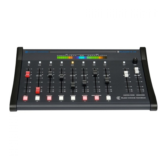
C O N S O L E F E A T U R E S Console Features Overview The AUDIOARTS 08 console consists of an input section with eight faders and associated switches, monitor and headphone section with two faders and associated switches. -
Page 14: Inputs
(+4dBu) input that goes directly to control room or meter. A USB connector allows audio to pass between the AUDIOARTS 08 and a computer. There is also a mono TALK IN input that allows an external line level source to directly feed the console CUE output. -
Page 15: Program Output
When SW 1 is DOWN the PGM is in stereo mode. Monitor Output The AUDIOARTS 08 has a CR output designed to drive a stereo pair of powered speakers, or a stereo amplifier driving separate speakers, to allow the operator to listen to PGM 1, or an external signal. The console may be programmed to provide monitor split cue. -
Page 16: Usb Port
AUDIOARTS 08 USB port. Use a cable having a USB Type B connector on the AUDIOARTS 08 end and a connector on the other end that will mate with the computer’s USB port; this will typically be a USB Type A connector. -
Page 17: General Considerations
General Considerations If any problems are encountered, please consider the following points: • The audio coming back into the AUDIOARTS 08 on the USB port is available at the 8 IN fader. • If you are not able to get the audio into or out of the USB port, check the USB cable, its connections at both ends, and the port selection settings in the application you are using. - Page 18 Input Section .................. 3-2 Source ........................3-2 Cue Button .........................3-3 TB Button ........................3-3 Fader ..........................3-3 ON Button ........................3-3 Control Room and Headphone Section ........3-4 Control Room ......................3-4 Headphone Fader .......................3-5 Meters ..................... 3-5 page 3 – 1 AUDIOARTS 08 / Dec 2015...
-
Page 19: Input Section
USB input. Source The AUDIOARTS 08 console accepts two mono mic input signals via female XLR (faders 1 and 2) and four stereo line level input signals via RJ-45 or RCA connectors (faders 3 - 6). -
Page 20: Cue Button
The channel is on when the ON button is lit. The mic channels can also be programmed (as mentioned in the previous chapter) to activate monitor mute and on air tally. page 3 – 3 AUDIOARTS 08 / Dec 2015 AUDIOARTS 08 / Apr 2021... -
Page 21: Control Room And Headphone Section
NOTE: If the Control Room is muted and you slide the fader all the way up, then remove the condition that has the Control Room muted, the sound in the Control Room speakers will suddenly be VERY LOUD! page 3 – 4 AUDIOARTS 08 / Dec 2015... -
Page 22: Headphone Fader
PGM right channel. The ON AIR LED, located in the middle of the meterbridge, lights up when either of the two MIC channels is ON, assuming they are set for mute and tally. page 3 – 5 AUDIOARTS 08 / Dec 2015... -
Page 23: Chapter 4 - Schematic And Load Sheet Drawings
S C H E M A T I C D R A W I N G S Schematic and Load Sheet Drawings Chapter Contents Console Flow Diagram ..............4-2 Mother Board Schematic ........................4-3 Load Sheet ........................4-12 page 4 – 1 AUDIOARTS / Dec 2015... - Page 24 LINE 8 PROGRAM, TB/MXM CALLER CALLER CALLER ACN FROM HYBRID CUE ACN EXT LT MONITOR EXT IN AUDIOARTS 08 EXT LT MONITOR CUE SENSE LOGIC SIMPLEPHONE INPUT System Flow Diagram EXTERNAL IN page 4 - 2 AUDIOARTS 08 / Dec 2015...
- Page 25 RJ-45 RJ-45 RJ-45 RJ-45 CT11 CT11 CT11 CT11 LINE7_LT_HI LINE3_LT_HI LINE5_LT_HI MXM_LT_HI LINE7_LT_LO LINE3_LT_LO LINE5_LT_LO MXM_LT_LO LINE7_RT_HI LINE3_RT_HI LINE5_RT_HI MXM_RT_HI CT12 HDPN_LT HDPN HDPN_RT JACK LINE7_RT_LO LINE3_RT_LO LINE5_RT_LO MXM_RT_LO TB_OUT_HI TB_OUT_LO TPD2E007 LINE "7" IN AGND LINE "3" IN LINE "5" IN MXM/TBOUT JST PINOUT RCA_LINE7_LT_HI...
- Page 26 TBSW_1 CUESW_2 CUESW_3 CUESW_4 CUESW_5 1.00K 0.22uF 1.00K 0.22uF 1.00K 0.22uF 1.00K 0.22uF 1.00K 0.22uF SW12 SW13 SW14 SW15 SW16 R346 ONSW_1 R345 ONSW_2 R343 ONSW_3 R342 ONSW_4 R341 ONSW_5 R358 R357 R356 R355 R354 R335 C334 R334 C333 R333 C332 R332 C331...
- Page 27 R102 10.0K BAT54 D12 BAT54 D10 BAT54 D9 BAT54 D8 BAT54 D7 R110 BAT54 D6 10.0K BAT54 D5 CUE TO MONITOR R344 BAT54 10.0K BAT54 D21 MIC1 C340 MUTE 100uF SPARE BAT54 D20 CUESW_3 CUESW_5 CUESW_7 MIC2 ____ ____ ____ ____ MUTE 74LS74...
- Page 28 R266 10.0K R264 10.0K PGM1LTACN PGM1LTACN 4053 4053 TB_OUT_HI R295 100 -2dBu C32 10uF TB_OUT_LO MIC1_IN_HI 22uF -50dBu BAL SSM2017 -2dBu C33 10uF MIC1_IN_LO 330pF C317 22uF R219 20.0K R218 20.0K AGND 100uF C282 TBMXM CUEACN 5532 C5V1 C5V1 AGND 0.001uF 0.001uF 5.1V...
- Page 29 R160 10.0K R157 10.0K C155 33pF C152 33pF C192 100uF C190 100uF AGND AGND RCA_LINE5_LT_HI -14dBu RCA_LINE6_LT_HI -14dBu R204 10K R203 10K 100uF C258 100uF C256 A1 A2 A1 A2 R311 22.1K R310 88.7K R258 10.0K R309 22.1K R308 88.7K R256 10.0K LINE5_LT_HI R161 20.0K...
- Page 30 R359 R360 R361 L E V E L L E V E L 1.30K R133 C100 C220 C249 C219 C248 C218 C247 C217 C246 C216 C245 C215 C244 C250 C221 C319 C337 C5V1 5.1V 0.22uF 0.22uF 0.22uF 0.22uF 0.22uF 0.22uF 0.22uF 0.22uF 0.22uF...
- Page 31 -2dBu 22uF C223 CALL_LT_ACN R245 10.0K PGM1LTMON CALL R236 10.0K R243 4.99K R221 PGM1_LT_HI -2dBu C225 33pF C243 33pF R234 4.99K -2dBu C230 33pF PGM1LTACN R148 10.0K 22uF C232 R244 10.0K 5532 -2dBu R248 R224 4.99K 5532 PGM1_LT_LO R235 R225 5532 C144 33pF...
- Page 32 AGND 3.32K R279 -14dBu CR12 R272 10.0K R300 40.2K R268 MON_LT_OUT PGM1LTMON R131 10.0K R293 40.2K 22uF C170 C285 22uF R212 10.0K C301 10pF 3.32K R294 4053 C202 33pF 4053 R301 5532 -2dBu 5532 EXTLTMON R130 10.0K -2dBu AGND AGND 4053 MONITOR PGM1RTMON...
- Page 33 +3.3V OUT IN 53.6K NCP1117 22uF 22uF 68pF AGND 22.1K 3.92K TS8L 10uF OPA2353 USB_OUT_LT_HI 10uF 0.001uF AGND +3.3V +3.3V +3.3V +3.3V OPA2353 0.1uF 10uF OPA2353 0.1uF AGND AGND AGND +3.3V +3.3V AGND 74LVC1G08 AGND 13.3K 1.69K AGND ______ AGND SSPND 53.6K 10uF...
- Page 34 Mother Board Load Sheet page 4 – 12 AUDIOARTS / Dec 2015...
- Page 35 Mother Board Load Sheet page 4 – 13 AUDIOARTS / Dec 2015...
- Page 36 Replacement Parts List ..............A-2 For the most part there are no user-replaceable parts in the AUDIOARTS 08 console. Exceptions are those controls and components that in the course of normal use may need maintenance (i.e., faders, pots, ON switches, etc.). A complete list of available components is shown on the next page.
- Page 37 260110 POWER SUPPLY 25W TRIPLE OUTPUT DESKTOP POWER SUPPLY 980038 260071 POWER CONNECTOR R/A DIN RECEPTACLE POWER CORD 7 1/2” BLACK POWER CORD 150017 MANUAL TECHNICAL MANUAL FOR AUDIOARTS08 CONSOLE 011497 page Appendix – 2 AUDIOARTS 08 / Aug 2015...
Need help?
Do you have a question about the Audioarts 08 and is the answer not in the manual?
Questions and answers
Is there a driver needed to input AudioArts 08 to a laptop?