Table of Contents
Advertisement
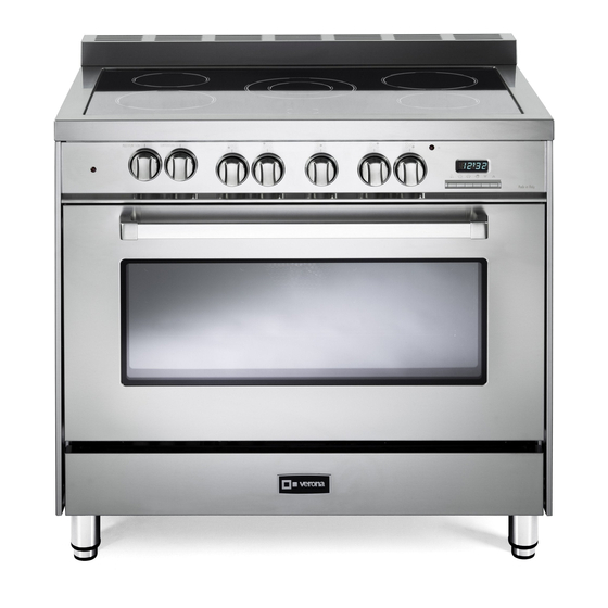
ELECTRIC RANGE
for residential use only
VEFSEE 365 ..
Models:
USERS OPERATING INSTRUCTIONS
IMPORTANT - PLEASE READ AND FOLLOW
• Before beginning, please read these instructions completely and carefully.
• Do not remove permanently affixed labels, warnings, or plates from the product. This may
void the warranty.
• Please observe all local and national codes and ordinances.
• Please ensure that this product is properly grounded.
• The installer should leave these instructions with the consumer who should retain
for local inspector's use and for future reference.
Electrical installation must be in accordance with the National Electrical Code, ANSI/NFPA70
- latest edition and/or local codes.
IN CANADA: Electrical installation must be in accordance with the current CSA C22.1
Canadian Electrical Codes Part 1 and/or local codes.
Some models are supplied with a protective film on steel and aluminium
parts. This film must be removed before installing/using the appliance.
THIS RANGE IS FOR RESIDENTIAL USE ONLY
FOR INSTALLER ONLY
R
INSTALLATION
Advertisement
Table of Contents

Related Manuals for Verona VEFSEE 365 Series


Summary of Contents for Verona VEFSEE 365 Series
- Page 1 ELECTRIC RANGE for residential use only INSTALLATION VEFSEE 365 .. Models: USERS OPERATING INSTRUCTIONS IMPORTANT - PLEASE READ AND FOLLOW • Before beginning, please read these instructions completely and carefully. • Do not remove permanently affixed labels, warnings, or plates from the product. This may void the warranty. • Please observe all local and national codes and ordinances. • Please ensure that this product is properly grounded. • The installer should leave these instructions with the consumer who should retain for local inspector’s use and for future reference.
- Page 3 WARNING ! To reduce the risk of tipping the appliance, the appliance must be secured by properly installed anti-tip device packed with the appliance. • ALL RANGES CAN TIP • INJURY TO PERSONS COULD RESULT • INSTALL ANTI-TIP DEVICE PACKED WITH RANGE • SEE INSTALLATION INSTRUCTIONS This appliance is designed and manufactured solely for the cooking of domestic (household) food and in not suitable for any none domestic application and therefore should not be used in a commercial environmement.
-
Page 4: Installation Instructions
INSTALLATION INSTRUCTIONS WARNING! THIS APPLIANCE MUST BE INSTALLED BY A QUALIFIED INSTALLER. Installation must conform with local codes. Improper installation, adjustment, alteration, services, or maintenance can cause injury or property damage. Consult a qualified installer or a service agent. IMPORTANT: The use of suitable protective clothing/gloves is recommended when handling, installing of this appliance. TOOLS NEEDED FOR INSTALLATION (NOT SUPPLIED WITH THE APPLIANCE) Tape Screwdriver Hammer Pencil measure Suitable protective Adjustable Adjustable gloves wrench pliers... -
Page 5: General Information
GENERAL INFORMATION WARNING!! WARNING!! 1. ELECTRICAL GROUNDING INSTRUCTIONS This appliance shall not be used for space heating. This The range must be electrically grounded in accordance with information is based on safety considerations. local codes or, in the absence of local codes, with the National Electrical Code, ANSI/NFPA No. 70-latest edition, in Canada 2. AlI openings in the wall behind the appliance and in the floor Canadian Electrical Code. Installation should be made by a under the appliance shall be sealed. Iicensed electrician. 3. Keep appliance area clear and free from combustible FOR PERSONAL SAFETY, THIS APPLIANCE MUST BE materials, gasoline, and other flammable vapors. - Page 6 installation PROXIMITY TO SIDE CABINETS 2. The range CANNOT be installed directly adjacent to sidewalls, 1. This range may be installed directly adjacent to existing 36” tall cabinets, tall appliances, or other side vertical surfaces (914 mm) high base cabinets. above 36” (914 mm) high. Range dimensions: There must be a minimum of 2” (50 mm) side clearance from • width: 35” 7/8 (911 mm) the range to such combustible surfaces TO THE LEFT or TO • depth: 23” 31/32 (609 mm) THE RIGHT above the 36” (914 mm) high countertop. IMPORTANT: One side (left or right) above the 36” (914 mm) • height (without backguard / island trim): MIN 35” 7/16 high countertop must always be kept clear.
-
Page 7: Electric Connection
ELECTRIC CONNECTION Dotted line showing the position of the range when installed Area for ELECTRICAL connection 6” 11/16 ÷ 8” 21/32 (170÷220 mm) [depending on feet regulation] Fig. 1.2... - Page 8 (3 3 0 m m ) 1 3 " m a x . PROXIMITY TO SIDE CABINETS RANGE WITH BACKGUARD Fig. 1.3a 1 3 " m a x . (3 3 0 m m ) Fig. 1.3b...
- Page 9 1 3 " m a x . (3 3 0 m m ) PROXIMITY TO SIDE CABINETS RANGE WITH ISLAND TRIM Fig. 1.3c (3 3 0 m m ) 1 3 " m a x . Fig. 1.3d...
-
Page 10: Fitting The Adjustable Feet
Fig. 1.5 Fig. 1.4 FITTING THE ADJUSTABLE FEET The adjustable feet must be fitted to the base of the cooker before use. Rest the rear of the cooker on a piece of the polystyrene packaging exposing the base for the fitting of the feet. ATTENTION: Most important! Pay special attention not to damage the range during this operation. Fit the 4 legs by screwing them tight into the support base as shown in picture 1.5. 0 mm 0" LEVELLING THE COOKER + 1" 31/32 Fig. 1.6 + 50 mm The cooker may be levelled by screwing the lower ends of the feet IN or OUT (fig. 1.6). It is important to observe the directions of figure 1.6. MOVING THE COOKER WARNING When raising cooker to upright position always ensure two people carry out this manoeuvre to prevent damage to the adjustable feet (fig. 1.7a). - Page 11 ASSEMBLING THE BACKGUARD OR THE ISLAND TRIM It is mandatory to install the backguard or the island trim • Assemble the backguard or the island trim as shown in figure 1.8 or 1.9 and fix it by screwing the 5 screws “A” (which are already fixed on the back of the cooktop).
-
Page 12: Anti-Tip Stability Device Installation Instructions
ANTI-TIP STABILITY DEVICE INSTALLATION INSTRUCTIONS Y O U M U S T U S E STABILITY ANTI TIP The anti-tip bracket has to be attached as shown on figure below, it has to be fixed BRACKET TO PREVENT on the rear wall by no. 2 (two) suitable screws (supplied with the anti-tip kit). UNIT FROM TIPPING. After fixing the anti-tip bracket, slide range into place. Be sure the anti-tip bracket is fully inserted in the slot of the range back. Dotted line showing the position of the range when installed ANTI-TIP STABILITY DEVICE FIXING Anti-tip stability device Slot for inserting the anti-tip bracket Fig. 1.10... -
Page 13: Electrical Connection
electrical connection ELECTRICAL REQUIREMENTS • This appliance must be properly installed and grounded by a qualified technician in WARNING accordance with the National Electrical Code ANSI/NFPA No.70 (latest edition) and local electrical code requirements. IN CANADA: Electrical installation must be in accordance with the current CSA C22.1 Canadian Electrical Codes Part1 and/or local TO AVOID ELECTRICAL SHOCK codes. - Page 14 3-Wire Power Cord Installation Fig. 3.1 (See Figures 3.1, 3.2 and 3.3) 1. Remove the Terminal Block Access Plate on the back of the range by unscrewing the 6 fixing Screws (fig. 3.1). 2. Insert the Power Cord through the hole in the Power Cord Bracket; then tighten the Power Cord by using a suitable Strain Relief. Allow enough slack to easily attach the cord terminals to the Terminal Block.
- Page 15 3-Wire Conduit Installation Fig. 3.5 (See Figures 3.1, 3.5 and 3.6) 1. Remove the Terminal Block Access Plate on the back of the range by unscrewing the 6 fixing Screws (fig. 3.1). 2. Feed 3/4” trade size Conduit through the hole in the Conduit Bracket and secure to the Conduit Bracket with a Conduit Clamp. 3. Remove the 3 wire terminal nuts and washers from the Counduit Terminal Block. Bracket 4. Plug the terminal holes of conductors. The Neutral or Ground Wire of the Power Cord must be connected to the neutral Hole D 1"...
-
Page 16: Wiring Diagram
WIRING DIAGRAM Pilot Pilot Pilot Pilot ELECTRIC DIAGRAM KEY Cooling fan motor OVEN GLASS CERAMIC HOB F2/3/5/6 Single zones energy regulators Cooling fan thermal overload Oven switch ELECTRIC DIAGRAM KEY Air switch Oven thermostat Double zone energy regulator Relay Electronic programmer P1/2/4/5 Single zone radiant elements Terminal block Thermal overload... - Page 20 The manufacturer cannot be held responsible for possible inaccuracies due to printing or transcription errors in the present booklet. The manufacturer reserves the right to make all modifications to its products deemed necessary for manufacture or commercial reasons at any moment and without prior notice, without jeopardising the essential functional and safety characteristics of the appliances. Cod. 1104877 - ß1...
Need help?
Do you have a question about the VEFSEE 365 Series and is the answer not in the manual?
Questions and answers