Table of Contents
Advertisement
Quick Links
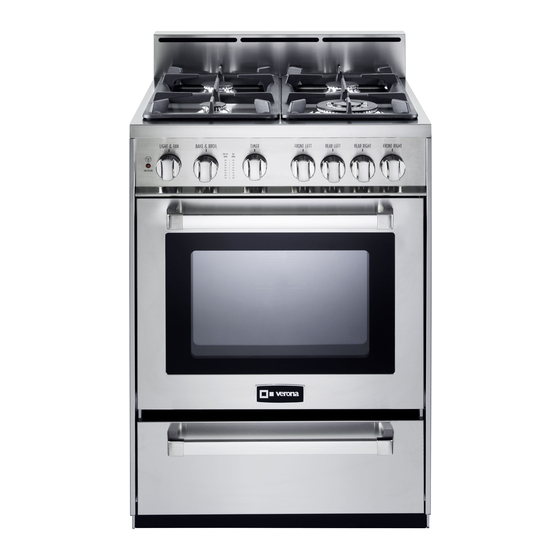
SINGLE OVEN GAS RANGE
for residential use only
VEFSGG 244 ..
Model:
• INSTALLATION INSTRUCTIONS
IMPORTANT - PLEASE READ AND FOLLOW
IMPORTANT - PLEASE READ AND FOLLOW
✓ Before beginning, please read these instructions completely and carefully.
✓ Do not remove permanently affixed labels, warnings, or plates from the product. This
may void the warranty.
✓ Please observe all local and national codes and ordinances.
✓ Please ensure that this product is properly grounded.
✓ The installer should leave these instructions with the consumer who should retain
for local inspector's use and for future reference.
✓ The electrical plug should always be accessible.
Installation must conform with local codes or in the absence of codes, the National Fuel
Gas Code ANSIZ223.1 - Iatest edition. Electrical installation must be in accordance
with the National Electrical Code, ANSI/NFPA70 - latest edition and/or local codes. IN
CANADA: Installation must be in accordance with the current CAN/CGA-B149.1 National
Gas Installation Code or CAN/CGA-B149.2, Propane Installation Code and/or local codes.
Electrical installation must be in accordance with the current CSA C22.1 Canadian Electrical
Codes Part 1 and/or local codes.
INSTALLATION IN MANUFACTURED (MOBILE) HOME: The installation must conform
with the Manufactured Home Construction and Safety Standard, Title 24 CFR, Part 3280
[formerly the Federal Standard for Mobile Home Construction and Safety, Title 24, HUD
(Part 280)] or, when such standard is not applicable, the Standard for Manufactured Home
Installations, ANSI/NCSBCS A225.1, or with local codes where applicable.
INSTALLATION IN RECREATIONAL PARK TRAILERS: The installation must conform with
state or other codes or, in the absence of such codes, with the Standard for Recreational
Park Trailers, ANSI A119.5.
Installation of any gas-fired equipment should be made by a Iicensed plumber. A manual
shut-off valve must be installed in an accessible location in the gas line external to the appli-
ance for the purpose of turning on or shutting off gas to the appliance (In Massachusetts
such shutoff devices should be approved by the Board of State Examiners of Plumbers &
Gas Fitters).
If an external electrical source is utilized, the appliance, when installed, must be electri-
cally grounded in accordance with local codes or, in the absence of local codes, with the
national Electrical Code, ANSI/NFPA 70.
This range is supplied with a protective film on
This film must be removed before installing/using the appliance.
FOR INSTALLER ONLY
THIS RANGE IS FOR RESIDENTIAL USE ONLY
steel and aluminium parts.
Advertisement
Table of Contents

Related Manuals for Verona VEFSGG 244


Summary of Contents for Verona VEFSGG 244
- Page 1 SINGLE OVEN GAS RANGE for residential use only VEFSGG 244 .. Model: • INSTALLATION INSTRUCTIONS IMPORTANT - PLEASE READ AND FOLLOW IMPORTANT - PLEASE READ AND FOLLOW ✓ Before beginning, please read these instructions completely and carefully. ✓ Do not remove permanently affixed labels, warnings, or plates from the product. This may void the warranty.
-
Page 2: What To Do If You Smell Gas
WARNING • ALL RANGES CAN TIP • INJURY TO PERSON COULD RESULT • INSTALL ANTI-TIP DEVICE PACKED WITH RANGE • SEE INSTALLATION INSTRUCTIONS WARNING: IF THE INFORMATION IN THIS MANUAL IS NOT FOLLOWED EXACTLY, A FIRE OR EXPLOSION MAY RESULT CAUSING PROPERTY DAMAGE, PERSONAL INJURY, OR DEATH. - Page 3 DATA PLATE CONVERSION LABEL This appliance is designed and manufactured solely for the cooking of domestic (household) food and in not suitable for any none domestic application and therefore should not be used in a commercial environmement. The appliance guarantee will be void if the appliance is used within a none domestic environnement i.e.
-
Page 4: Installation Instructions
INSTALLATION INSTRUCTIONS WARNING! THIS APPLIANCE HAS TO BE INSTALLED BY A QUALIFIED INSTALLER. Improper installation, adjustment, alteration, services, or maintenance can cause injury or property damage. Consult a qualified installer, service agent, or the gas supplier. IMPORTANT: The use of suitable protective clothing/gloves is recommended when handling, installing of this appliance. TOOLS NEEDED FOR INSTALLATION (NOT SUPPLIED WITH THE APPLIANCE) T-handle... -
Page 5: General Information
GENERAL INFORMATION WARNING!! 1. Installation must conform with local codes or, in the absence of local codes, with the National Fuel Gas Code, ANSI Z223.1-Latest Edition. ELECTRICAL GROUNDING INSTRUCTIONS The range must be electrically grounded in accordance 2. Installation in manufactured (mobile) home: installation with local codes or, in the absence of local codes, with the must conform with the Manufactured Home Construction National Electrical Code, ANSI/NFPA No. - Page 6 installation PROXIMITY TO SIDE CABINETS 1. This range may be installed directly adjacent to existing 36" (914 mm) high base cabinets. Range dimensions: • width: 23” 7/8 (606.5 mm) • depth: 24” 5/64 (611.6 mm) • height (without backguard): MIN 35” 7/16 (900 mm) - MAX 36” 7/32 (920 mm) •...
-
Page 7: Assembling The Backguard
PROXIMITY TO SIDE CABINETS 1 3 " m a x . (3 3 0 m m ) Fig. 1.3a Fig. 1.3b Fig. 1.4 ASSEMBLING THE BACKGUARD It is mandatory to install the backguard Assemble the backguard as shown in figure 1.5: • Screw the 2 screws “A” interposing the spacers. •... -
Page 8: Anti-Tip Stability Device Installation Instructions
LEVELLING THE RANGE The range is equipped with 4 LEVELLING FEET and may be levelled by screwing or unscrewing the feet with a spanner (fig. 1.8). It is important to observe the directions of figures 1.6, 1.7a, 1.7b. Fig. 1.6 Supplied with the range in a separate kit 0 mm... -
Page 9: Gas Connection
gas connection All gas connections must be made according to national and local codes. This gas supply (service) line must be the same size or greater than the inlet line of the appliance. Sealant on all pipe joints must be resistant to te action of LP/Propane gas. The range is equipped for the use with NATURAL gas. - Page 10 PRESSURE REGULATOR INSTALLATION STEP 1 Mount the 1/2” NPT (conical) male connector to the pressure regulator and tighten by using a wrench. LOCK Do not over tighten the connector. Over tightening may crack regulator. Arrow Fig. 2.2 STEP 2 Assemble the 1/2” NPT connector + pressure regulator group to the extension pipe interposing the gasket supplied. The regulator cover must be oriented toward the front side of the range.
- Page 11 GAS CONNECTION SPECIFICATION Range manifold Manifold male pipe fitting 1/2” G cylindrical (ISO 228-1) male Gasket 1/2” G cylindrical (ISO 228-1) female To range Extension Extension pipe female pipe female pipe fitting pipe fitting Extension pipe Extension pipe male 1/2”...
-
Page 12: Leak Testing
b) Any conversion required must be performed by your dealer or a qualified licensed To range plumber or gas service company. Please provide the service person with this manual before work is started on the range. (Gas conversions are the responsibility of the dealer or end user.) c) This range can be used with NATURAL or LP/PROPANE gas. -
Page 13: Conversion To Lp/Propane Gas
CONVERSION TO LP/PROPANE GAS Every range is provided with a set of injectors for the various types of gas. Select the injectors to be replaced according to the “INJECTORS TABLE”. The nozzle diameters, expressed in hundredths of a millimetre, are marked on the body of each injector. -
Page 14: Injectors Table
INJECTORS TABLE NOMINAL REDUCED LP/PROPANE NATURAL GAS POWER POWER 11" W.C.P. 4" W.C.P. Ø injector Ø injector BURNERS BTU/hr BTU/hr [1/100 mm] [1/100 mm] Auxiliary (AUX) 3500 1000 Semirapid (SR) 6000 1500 Triple ring (TC) 12000 5000 Oven burner 13000 1500 Broil burner... - Page 15 OPERATIONS TO BE EXECUTED FOR THE REPLACEMENT OF THE INJECTORS OF THE OVEN AND BROIL BURNERS Oven Burner – Lift and remove the lower panel inside the oven. – Remove the burner securing screw (fig. 2.10). – Withdraw the burner as shown in figure 2.11 and rest it inside the oven. Take care not to damage the wire to the ignition electrode and the safety valve probe.
-
Page 16: Adjustment Of The Oven Burner Minimum
ADJUSTMENT OF THE OVEN BURNER MINIMUM This needs to be done only for the oven burner (the broil is a fixed capacity) by acting on the thermostat in the following way: – Turn on the burner by setting the thermostat knob on position –... -
Page 17: Electrical Connection
electrical connection If codes permit and a separate ground wire is used, it is recommended that a WARNING qualified electrician determine that the ground path is adequate. Check with a qualified electrician if you are not sure whether the range is properly grounded. -
Page 18: Wiring Diagram
WIRING DIAGRAM Fig. 3.2... - Page 20 The manufacturer cannot be held re spon sible for possible inaccuracies due to printing or transcription errors in the present booklet. The manufacturer re serves the right to make all modifications to its products deemed necessary for manufacture or commercial reasons at any moment and without prior notice, without jeopardising the es sential functional and safety characteristics of the appliances.
Need help?
Do you have a question about the VEFSGG 244 and is the answer not in the manual?
Questions and answers