Table of Contents
Advertisement
Quick Links
GAS/ELECTRIC RANGE
for residential use only
VEFSGE304P..
Models:
USERS OPERATING INSTRUCTIONS
IMPORTANT - PLEASE READ AND FOLLOW
• Before beginning, please read these instructions completely and carefully.
• Do not remove permanently affixed labels, warnings, or plates from the product. This may
void the warranty.
• Please observe all local and national codes and ordinances.
• Please ensure that this product is properly grounded.
• The installer should leave these instructions with the consumer who should retain
for local inspector's use and for future reference.
Installation must conform with local codes or in the absence of codes, the National Fuel Gas
Code ANSIZ223.1 - Iatest edition. Electrical installation must be in accordance with the Natio-
nal Electrical Code, ANSI/NFPA70 - latest edition and/or local codes.
IN CANADA: Installation must be in accordance with the current CAN/CGA-B149.1 National
Gas Installation Code or CAN/CGA-B149.2, Propane Installation Code and/or local codes.
Electrical installation must be in accordance with the current CSA C22.1 Canadian Electrical
Codes Part 1 and/or local codes.
INSTALLATION IN MANUFACTURED (MOBILE) HOME: The installation must conform with
the Manufactured Home Construction and Safety Standard, Title 24 CFR, Part 3280 [formerly
the Federal Standard for Mobile Home Construction and Safety, Title 24, HUD (Part 280)]
or, when such standard is not applicable, the Standard for Manufactured Home Installations,
ANSI/NCSBCS A225.1, or with local codes where applicable.
INSTALLATION IN RECREATIONAL PARK TRAILERS: The installation must conform with
state or other codes or, in the absence of such codes, with the Standard for Recreational Park
Trailers, ANSI A119.5.
Installation of any gas-fired equipment should be made by a licensed plumber. A manual shut-
off valve must be installed in an accessible location in the gas line external to the appliance
for the purpose of turning on or shutting off gas to the appliance (In Massachusetts such shu-
toff devices should be approved by the Board of State Examiners of Plumbers & Gas Fitters).
If an external electrical source is utilized, the appliance, when installed, must be electrically
grounded in accordance with local codes or, in the absence of local codes, with the national
Electrical Code, ANSI/NFPA 70.
Some models are supplied with a protective film on steel and aluminium
parts. This film must be removed before installing/using the appliance.
THIS RANGE IS FOR RESIDENTIAL USE ONLY
R
Advertisement
Table of Contents

Subscribe to Our Youtube Channel
Related Manuals for Verona VEFSGE304P Series


Summary of Contents for Verona VEFSGE304P Series
- Page 1 GAS/ELECTRIC RANGE for residential use only VEFSGE304P.. Models: USERS OPERATING INSTRUCTIONS IMPORTANT - PLEASE READ AND FOLLOW • Before beginning, please read these instructions completely and carefully. • Do not remove permanently affixed labels, warnings, or plates from the product. This may void the warranty. • Please observe all local and national codes and ordinances. • Please ensure that this product is properly grounded. • The installer should leave these instructions with the consumer who should retain for local inspector’s use and for future reference. Installation must conform with local codes or in the absence of codes, the National Fuel Gas Code ANSIZ223.1 - Iatest edition. Electrical installation must be in accordance with the Natio- nal Electrical Code, ANSI/NFPA70 - latest edition and/or local codes.
-
Page 2: What To Do If You Smell Gas
WARNING ! To reduce the risk of tipping the appliance, the appliance must be secured by properly installed anti-tip device packed with the appliance. • ALL RANGES CAN TIP • INJURY TO PERSONS COULD RESULT • INSTALL ANTI-TIP DEVICE PACKED WITH RANGE • SEE INSTALLATION INSTRUCTIONS WARNING ! If the information in this manual is not followed exactly, a fire or explosion may result causing property damage, personal injury, or death. – Do not store or use gasoline or other flammable vapors and liquids in the vicinity of this or any other appliance. - Page 3 Dear Customer, Thank you for having purchased and given your preference to our product. The safety precautions and recommendations reported below are for your own safety and that of others. They will also provide a means by which to make full use of the features offered by your appliance. Please preserve this booklet carefully.
-
Page 4: General Information
USER INSTRUCTIONS GENERAL INFORMATION WARNING!! WARNING!! 1. ELECTRICAL GROUNDING INSTRUCTIONS This appliance shall not be used for space heating. This The range must be electrically grounded in accordance with information is based on safety considerations. local codes or, in the absence of local codes, with the Natio- nal Electrical Code, ANSI/NFPA No. 70-latest edition, in Cana- 2. AlI openings in the wall behind the appliance and in the floor da Canadian Electrical Code. under the appliance shall be sealed. Installation should be made by a Iicensed electrician. 3. Keep appliance area clear and free from combustible mate- FOR PERSONAL SAFETY, THIS APPLIANCE MUST BE PRO- rials, gasoline, and other flammable vapors. PERLY GROUNDED. 4. Do not obstruct the flow of combustion and ventilation air. If an external electrical source is utilized, the installation must be electrically grounded in accordance with local codes or, in the 5. Disconnect the electrical supply to the appliance before ser- absence of local codes, with the national Electrical Code, ANSI/ vicing. -
Page 5: Important Precautions And Recommendations
IMPORTANT PRECAUTIONS AND RECOMMENDATIONS After having unpacked the appliance, check to ensure that it is not damaged. In case of doubt, do not use it and consult your supplier or a professionally qualified tech- nician. Packing elements (i.e. plastic bags, polystyrene foam, nails, packing straps, etc.) should not be left around within easy reach of children, as these may cause serious injuries. The packaging material is recyclable and is marked with the recycling symbol • Do not attempt to modify the technical characteristics of the appliance as this may become dangerous to use. • Do not carry out cleaning or maintenance operations on the appliance without having previously disconnected it from the electric power supply. • After use, ensure that the knobs are in position. • Do not allow children or other incapable people to use the appliance without supervi- sion. • During and after use of the range, certain parts will become very hot. Do not touch hot parts. • Keep children away from the range when it is in use. •... -
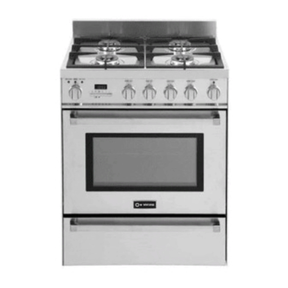
Page 6: Gas Burners
features Fig. 1.1 GAS BURNERS 1. Rear left Semi-rapid burner (SR) - 8000 BTU/hr 2. Rear right Semi-rapid burner (SR) - 8000 BTU/hr 3. Front right Dual burner (D) - 17000 BTU/hr 4. Front left Dual burner (D) - 17000 BTU/hr Note: • The electric gas-lighting device is incorporated into the knobs. • The appliance has a safety valve system fitted. The flow of gas will stop if and when the flame should acciden- tally go out. CAUTION: If the burner is accidentally extinguished, turn the gas off at the control knob and wait at least 1 minute befo- re attempting to relight. CAUTION: Gas appliances produce heat and humidity in the en- vironment in which they are installed. Ensure that the cooking area is well ventilated fol- lowing national/local codes. -
Page 7: Controls Description
Fig. 1.2 CONTROLS DESCRIPTION Gas cooking hob controls: 1. Front left burner (4) control knob 2. Rear left burner (1) control knob 3. Rear right burner (2) control knob 4. Front right burner (3) control knob Oven controls: 5. Function selector knob 6. Temperature knob (potentiometer) 7. Electronic programmer 8. Warming drawer control knob 9. Warming drawer on pilot light 10. Oven heating pilot light 11. Oven on pilot light 12. Door locked pilot light... - Page 8 how to use the top burners GAS BURNERS (Semi-rapid) Gas flow to the burners is adjusted by turning the knobs (illustrated in fig. 2.1) which control the valves. Turning the knob so that the symbols printed on itself point to the symbol printed on the control panel achieves the following functions: Knob Function SEMI-RAPID burners position closed valve maximum rate minimum rate Fig. 2.1 The maximum aperture position permits rapid boiling of liquids, whereas the minimum aperture position allows simmer warming of food or maintaining boiling conditions of liquids.
- Page 9 LIGHTING GAS BURNERS FITTED WITH FLAME FAILURE SAFETY DEVICE (Semi-rapid burners) In order to light the burner, you must: 1. Push and turn the knob in an anti-clockwise direction up to the position (ma- ximum rate), push in and hold the knob until the flame has been lit (fig. 2.2). The sparks produced by the lighter situated inside the relative burner will light the flame. In the event that the local gas supply conditions makes it difficult to light the burner in position (maximum rate), try again with the knob in position (minimum rate). If there is no mains electrical supply, bring a lighted match close to the burner. 2. Wait for about ten seconds after the gas burner has been lit before letting go the knob (safety device activation delay). 3. Adjust the gas valve to the desired position. If the burner flame should go out for some reason, the safety valve will automatically stop the gas flow. To re-light the burner, return the knob to the closed position, wait for at least 1 minute and then repeat the lighting procedure. If your local gas supply makes it difficult to light the burner with the knob set to maximum, set the knob to minimum and repeat the operation. Caution! The range becomes very hot during operation. Keep children well out of reach.
- Page 10 GAS BURNERS (Dual) The Dual Burner is a very flexible burner which allows different regulations and optimal cooking. It is composed by one inner and one outer crown; the flame of the inner crown can be regulated separately from the flames of the outer crown. The Dual Burner can be used: • As a high-power burner (all flames produced simultaneously by inner and outer crown) which can be adjusted from the maximum ( ) to the minimum ( position. Intermediate operating adjustments can be achieved by positioning the indicator between the maximum and minimum opening positions, and never between the maximum opening and position.
- Page 11 LIGHTING GAS BURNERS FITTED WITH FLAME FAILURE SAFETY DEVICE (Dual burners) In order to light the burner, you must: 1. Push and turn the knob in an anti-clockwise direction up to the position (maximum rate of inner + outer crown); push in and hold the knob until the flame has been lit. The sparks produced by the lighter situated inside the relative burner will light the flame. In the event that the local gas supply conditions makes it difficult to light the burner in position , try again with the knob in position If there is no mains electrical supply, bring a lighted match close to the burner. 2. Wait for about ten seconds after the gas burner has been lit before letting go the knob (safety device activation delay). 3. Adjust the gas valve to the desired position. If the burner flame should go out for some reason, the safety valve will automatically stop the gas flow. To re-light the burner, return the knob to the closed position, wait for at least 1 minute and then repeat the lighting procedure. If your local gas supply makes it difficult to light the burner with the knob set to maximum, set the knob to minimum and repeat the operation. N.B. When the range is not being used, set the gas knobs to their positions and also close the gas shut-off valve placed on the main gas supply line. Caution! The range becomes very hot during operation.
- Page 12 CHOICE OF BURNER (fig. 2.5) The symbols or wordings printed on the panel above the gas knobs indicate the corre- spondence between the knob and the burner. The most suitable burner is to be chosen according to the diameter and volume capacity of the container to be warmed. It is important that the diameter of the pots or pans suitably match the heating potential of the burners in order not to jeopardise the efficiency of the burners, bringing about a waste of gas fuel. Fig. 2.5 A small diameter pot or pan placed on a large burner does not necessarily mean that boiling conditions are reached quicker. DIAMETERS OF PANS WHICH MAY BE USED ON THE HOB BURNERS BURNER MINIMUM MAX. Semi-rapid 16 cm (6” 19/64) 24 cm (9” 7/16) Dual 26 cm (10” 3/16) 28 cm (11” 1/16) Wok pans min 36 cm (14” 3/16) - max 40 cm (15” 3/4) Do not use pans with concave or convex bases WRONG CORRECT USE OF DUAL BURNER (Fig. 2.6a - 2.6b) The flat-bottomed pans are to be placed directly onto the pan-support. When using a WOK you need to place the supplied stand in the burner to avoid any faulty operation of the Dual burner (Figs. 2.6a - 2.6b). Fig. 2.6a IMPORTANT: The special grill for wok pans (fig. 2.6b) MUST BE PLACED ONLY over the pan-rest for the Dual burner. CORRECT Fig. 2.6b Ensure that the handles of cookware do not stick out over the edge of the range, to avoid them being knocked over by...
-
Page 13: General Features
how to use the warming drawer GENERAL FEATURES The warming drawer is fitted with an heating element (500 W) placed on the top. The heating can be regulated from 86°F (30°C) [ min position] to 203°F (95°C) [ max position]. USING THE WARMING DRAWER FOR THE FIRST TIME • Switch on the empty warming drawer at maximum power for about 2 hours to remove traces of grease and smells from the components. • When the warming drawer has cooled down and the range has been unplugged, clean the inside of the drawer with a cloth soaked in water and neutral detergent and dry it perfectly. WARNING: The drawer is hot during operation, use the handle. Fig. 3.1 TO USE THE WARMING DRAWER WARNING: • Push and turn the control knob to a temperature setting: (min), (max) or The warming drawer is for ke- between min and max position. eping hot food hot. Never use • Allow time for the drawer to be preheated. it to warm or heat a room or •... -
Page 14: Temperature Selector
TEMPERATURE SELECTOR Knob position °F °C The setting can be anywhere between (min) (min) and (max) position. from 87 to 247 from 31 to 119 between (min) and (max) (max) WARNING LIGHT The warning light is located above the control knob and turns “ON’ when the warming drawer is set. It stays on until the knob is turned back to the (off) position. - Page 15 how to use the self cleaning oven GENERAL FEATURES ATTENTION: The oven door The oven has special operating features. becomes very hot during ope- Five different functions can be used to satisfy all cooking needs; it also has a self cle- aning function which can clean the oven cavity at high temperature, a defrost function ration. Keep children away. and an oven light function. These functions are managed by an electronic programmer which keeps the tempe- rature set constant by means of a probe inside the oven cavity. The oven has the following heating elements: VERY IMPORTANT: • Lower heating element (double) 550 + 1750 W The oven shall be always • Upper heating element 1200 W used with the door closed. • Grill heating element 2850 W •...
-
Page 16: Selecting The Functions
SELECTING THE FUNCTIONS (figs. 4.1, 4.2a, 4.2b) The function is selected by turning the function selector knob and matching the marking on the knob with the reference mark printed on the control panel. IMPORTANT NOTE FOR THE COOKING FUNCTIONS: Once selecting the function and temperature (the temperature flashes on the programmer display - fig. 4.2a), press button 3 (“START”) on the programmer to start the cooking (temperature and symbol steady lit on the programmer display - fig. 4.2b). Important: In all cooking functions the oven must always be used with the DOOR CLOSED. I I I I I I I I I I I I I I If the door stays open “door” flashes on the programmer display and after some minutes an audible warning sounds for about 30 seconds. To silence the audible warning press any programmer button. Fig. 4.1 NOTE: The heating elements work even with the door open and this signal just indicates that energy is being wasted and the control panel/knobs are excessively heated. -
Page 17: Conv.broil
BAKE (Traditional Convection Cooking) The upper and lower heating elements switch on. The heat is diffused by natural convection and the temperature must be set between 120°F (50°C) and 535°F (280°C). On selecting this function the electronic programmer starts cooking with a pre-heating temperature set at 390°F (200°C). To vary the temperature see the “SETTING THE CO- OKING” section. Recommended for: For foods which require the same cooking temperature both internally and externally, i. e. roasts, spare ribs, etc. FAN BAKE (Traditional Convection Cooking With Fan) The upper and lower heating elements and the fan are switched on. The heat from the top and the bottom is diffused by fan convection. - Page 18 CLEAN (Self Cleaning Function - this is not a cooking function) CAUTION: During the self cleaning cycle the accessi- ble parts may become hot. IMPORTANT NOTES: Keep children away. This is not a cooking function but is only used to clean the oven. Before starting the self cleaning cycle: NEVER USE THE RANGE • Take all the accessories out of the oven (drip tray and WHEN THE OVEN IS OPE- shelves).
- Page 19 SELECTING °F/°C ON THE DISPLAY BAKE 1. Turn the oven selector knob to a cooking function (i.e. 2. Press key 5 on the programmer (or use the temperature knob) to reduce the temperature until you reach the minimum value (120°F/50°C). 3. Press key 3 on the programmer. 4. Keep key 4 pressed (the temperature flashes) until “°F” or “°C” is flashing; then press key 4 again to change from °F to °C or vice versa. During selection “°C” or “°F” is flashing. HEATING After selecting °F or °C, turn the oven selector knob to the position. °F °C START °F °C START I I I I I I I I I I I I I I °F °C...
- Page 20 HOW TO START THE SELF CLEANING CYCLE Important: The self cleaning cycle must only be performed with the oven empty; so, before starting the cycle take all the accessories (shelves, drip tray, ...) out of the oven cavity and dry any traces of overflowed liquid. Do not use any decreasing products (e.g. decreasing sprays, detergents, etc.). 1. Close the oven door (if it is open or not closed properly, “door” flashing on the display, the self cleaning cycle will not start). CLEAN 2. Turn the oven selector knob to the self cleaning position ; “P1:30” (self clea- ning time, 1 hour and 30 minutes) appears on the electronic programmer display with the letter “P” flashing. 3. To increase the self cleaning cycle time (max 3 hours) press key 2 of the pro- grammer then key 6. To go backwards to the minimum of 1 hour and 30 minutes °F press key 2 then key 5. Alternatively press key 2 of the programmer and then turn the temperature knob to the right to increase the time or to the left to reduce °C it. During the setting “P” is not shown on the display. START 4. Press button 3 on the programmer to start the cycle. This combined confirmation operation offers greater safety when there are HEATING children; in fact turning the knob to the self cleaning function has no effect if key 3 of the programmer is not then pressed.
- Page 21 I I I I I I I I I I I I I I PROBLEMS ON STARTING AND DURING THE SELF CLEA- NING CYCLE 1. “door” (flashing) appears on the programmer display The function selector has been turned to the self cleaning position with the oven door open or not perfectly closed. Or the door has been opened before the cycle has been started with confirmation from key 3. What to do: • Close the door and repeat the operations to start the cycle. 2. “F0:00” and “A” (“A” flashing) appear on the programmer display The self cleaning cycle has been stopped and then re-started (immediately). The message is displayed after about 15 minutes and the self cleaning cycle is zeroed. What to do: • Turn the oven selector knob to (oven off). • Wait for at least 30 minutes. • Repeat the operations to start the self cleaning cycle. • If after several attempts the message continues contact the Service Centre. Caution: It is advisable not to stop the self cleaning cycle and then start it again when it is quite a way through.
- Page 22 HOW TO STOP THE SELF CLEANING CYCLE 1. Turn the function selector to (oven OFF). If the oven cavity temperature is higher than 570°F (300°C): • The time of day appears on the programmer display. • When the oven cavity temperature drops below 570°F (300°C): – the door locked pilot light goes out; – the door unlocks and can be opened. If the oven cavity temperature is lower than 570°F (300°C): • The time of day appears on the programmer display. • After a technical time: – the door locked pilot light goes out; – the door unlocks and can be opened. IMPORTANT: Wait for the oven to cool down completely before starting a coo- king function. 2. ACCIDENTAL INTERRUPTION OF THE SELF CLEANING CYCLE. The function selector has been turned to any cooking function. If the oven cavity temperature is higher than 570°F (300°C): •...
- Page 23 ABNORMAL SITUATIONS AND/OR OPERATION PROBLEMS during cooking or the self cleaning cycle 1. “F000” or “F001” appear during cooking or self cleaning cycle Oven temperature sensor is broken or not working properly. The cooling fan stays on and if the self cleaning cycle is in progress the door remains locked. What to do: • Turn the function selector to (oven OFF). • Wait for the oven to cool down completely and disconnect the range from the mains. • Reconnect the appliance to the main. If after this procedure the display still reads “F000” or “F001”: • Disconnect the range from the mains. • Call Service. The range must not be used. 2. “F000” and “A” (“A” flashing) appear during the self cleaning cycle This indicates a temperature sensor measurement error during the self cleaning cycle. This may be due to the self cleaning cycle being stopped and started again when it was quite a way through.
- Page 24 COOKING ADVICE STERILIZATION Sterilization of foods to be conserved, in full and hermetically sealed jars, is done in It is advisable to handle the the following way: CONV.BAKE a. Turn the switch to position (convection cooking with ventilation). oven accessories using b. Set the thermostat knob to position 350°F (175°C) and preheat the oven. oven gloves. c. Fill the grill pan with hot water. d. Set the jars into the grill pan making sure they do not touch each other and the door and set the thermostat knob to position 260°F (130°C). When sterilization has begun, that is, when the contents of the jars start to bubble, turn off the oven and let cool. ROASTING To obtain classical roasting, it is necessary to remember: • the pre-set temperature should be maintained; • that the cooking time depends on the quantity and the type of foods. COOKING DIFFERENT DISHES AT THE SAME TIME CONV.BAKE The MULTIFUNCTION oven at positions (convection cooking with ventila- tion) of the function selector can cook various different foods at the same time. Fish, cakes and meat can be cooked together without the smells and flavours mixing.
- Page 25 STEP STEP STEP STEP Fig. 4.3 BROILING Very important: the broil element must always be used with the oven door closed. • Position the shelf on the first or second level from the top (fig. 4.3). • Turn on the broil element, as explained in the preceding paragraphs and let the oven preheat for about 5 minutes with the door closed. • Place the food to be cooked above the broiler tray. • Introduce the broiler tray (fig. 4.4) in the oven. The broiler tray should be placed above the shelf and it should be centered with the broil element (fig. 4.3). Do not broil without using the broiling pan. Fig. 4.4 Important: Always use suitable protective gloves when inserting/removing the broiling pan, shelves, pans on other cooking utensils from the oven. WRONG Fig. 4.5 CORRECT Fig. 4.6...
-
Page 26: Setting The Time
how to use the electronic programmer The electronic programmer is a device which groups together the following functions: • 12 hours clock with illuminated display. • Timer (up to 3 hours). • Program for semi-automatic oven cooking. • Program for automatic oven cooking. • Management of the cooking functions. The programmer can manage setting the temperature in the various cooking functions. • Management of the self cleaning function. Description of the buttons: Timer (1) Cooking time or self cleaning time (2) °F End of cooking time or allowance to start the cooking START functions or self cleaning cycle (3) °C START Setting oven temperature (4) Countdown of the figures of all the functions or of the temperature to be set (5) Fig. 5.1 Advance of the figures of all the functions or of the tem- perature to be set (6) Description of the light symbols: Indicates that the timer is working Indicates AM time... - Page 27 TIMER The timer function is only used to count the time and does not influence oven opera- tion or any programmes which are in progress or set. 1. Press button 1 - “0:00” appears on the programmer display. 2. Press keys 5 or 6 to set the time required (or turn the temperature knob to the right to increase the time and to the left to reduce it) - the bell symbol lights up °F on the display. 3. The countdown starts immediately and the time appears again. 4. To see the countdown press button 1. The time will be indicated in hours and °C minutes; the seconds are only indicated for the last minute. START 5. At the end of the countdown an audible signal sounds and the bell symbol goes out. Press any button to stop the audible signal. HEATING IMPORTANT WARNING: This function is only an electronic alarm and does not switch OFF the oven. Remember to turn to (oven OFF) manually the selector knob at the end of the countdown. AUTOMATIC COOKING - Start cooking at the programmed time and switch the oven off automatically after the programmed cooking time OR SEMI-AUTOMATIC COOKING -...
- Page 28 CANCELLING A SET PROGRAM To cancel any program just press the buttons 5 and 6 at the same time for more than 3 seconds or turn the function selector knob to (oven OFF). CLEAN LIGHT DEFROST Note: If during a set program the function selector knob is turned to (self cleaning), (oven lighting), (defrosting frozen foods) or to another cooking function, the program is cancelled. EXAMPLE OF PROGRAMMING AUTOMATIC COOKING Time when the food to be cooked must be ready Time needed to cook (12:00 PM) the food (2 hours) Time when cooking the food is programmed (08:00 AM) Programmable functions °F °C START HEATING °F °C START HEATING °F °C START Fig.
-
Page 29: Very Important
cleaning and maintenance GENERAL RECOMANDATION WARNING • Important: Before any operation of cleaning and maintenance disconnect the VERY IMPORTANT appliance from the electrical supply. • It is advisable to clean when the appliance is cold and especially for cleaning the enamelled parts. Before any operation of • Avoid leaving alkaline or acidic substances (lemon juice, vinegar, etc.) on the maintenance disconnect surfaces. - Page 30 CORRECT POSITION OF THE SEMI-RAPID BURNERS It is very important to check that the burner flame spreader “B” and the cap “A” have been correctly positioned (see figs. 6.1 and 6.2 ). Failure to do so can cause serious problems. CORRECT POSITION OF THE DUAL BURNERS The Dual burner must be correctly positio- ned (see fig. 6.3); the flame spreader “E” must be fitted as shown by the arrows (fig. 6.4). Then position the cap “C” and the ring “D” (figs. 6.3 and 6.6). Correctly positioned burner should not rotate (fig. 6.5).
-
Page 31: Replacing The Oven Light
OVEN SHELF INSTALLATION AND REMOVAL The oven shelf is provided with a security block to prevent accidental ex- traction. It must be inserted as per figure 6.9. To pull it out remove shelf in the inverse order. Keep attention to insert the shelf correctly (see figure 6.10). Fig. 6.9 REPLACING THE OVEN LIGHT (fig. 6.10) Before any maintenance is started involving electrical parts of the appliance, it must be disconnected from the power supply. • Let the oven cavity and the heating elements cool down. • Switch off the electrical supply. • Remove the protective cover “A” (fig. 6.10). •... -
Page 32: Removing The Warming Drawer
REMOVING THE WARMING DRAWER 1. Open the drawer completely (fig. 6.11) WARNING: 2. Move down the lever of left guide (fig. 6.12) and up the lever of right guide • Do not remove drawer while (fig. 6.13). hot. 3. Remove the drawer; the levers have to be keep moved (fig. 6.11). • Do not remove drawer during • operation. • Be sure drawer is empty before removing. Fig. 6.13 Fig. 6.12 Fig. 6.11 FITTING THE WARMING DRAWER 1. Insert the drawer guides into the range guides (fig. 6.14) 2. Gently close the drawer completely; the safety catchs will be automatically hooked. -
Page 33: Removing The Oven Door
REMOVING THE OVEN DOOR The oven door can easily be removed as follows: • Open the door to the full extent (fig. 6.15a). • Open the lever “A” completely on the left and right hinges (fig. 6.15b). • Hold the door as shown in fig. 6.15. • Gently close the door (fig. 6.15c) until left and right hinge levers “A” are hooked to part “B” of the door (fig. 6.15b) • Withdraw the hinge hooks from their location following arrow “C” (fig. 6.15d). • Rest the door on a soft surface. Fig. 6.15 • To replace the door, repeat the above steps in reverse order. Fig. 6.15a Fig. 6.15b Fig. 6.15c Fig. 6.15d... -
Page 34: Do's And Do Not's
DO’S AND DO NOT’S • Do always use the oven with the door closed. • Do read the user instructions carefully before using the range for first time. • Do allow the oven to heat for about two hours, before using for the first time, in order to expel any smell from the new oven insulation, without the introduction of food. • Do clean your oven regularly. • Do remove spills as soon as they occur. • Do always use oven gloves when removing food shelves and trays from the oven and from the warming drawer. • Do not allow children near the range when in use. • Do not allow fat or oils to build up in the oven base, or oven accessories. • Do not place cooking utensils or plates directly onto the oven base. • Do not place hot enamel parts in water. Leave them to cool first. • Do not allow vinegar, coffee, milk, saltwater, lemon or tomato juice to remain in contact with enamel parts (i.e. inside the oven). • Do not use abrasive cleaners or powders that will scratch the surface of the stainless steel and the enamel. • Do not attempt to repair the internal workings of your range. • Do remove the protective film before the first use. • Fire risk! Do not store flammable material in the oven and in the warming drawer. •... - Page 36 The manufacturer cannot be held responsible for possible inaccuracies due to prin- ting or transcription errors in the present booklet. The manufacturer reserves the right to make all modifications to its products deemed necessary for manufacture or commercial reasons at any moment and without prior notice, without jeopardising the essential functional and safety characteristics of the appliances. Cod. 1103876 - ß1...
Need help?
Do you have a question about the VEFSGE304P Series and is the answer not in the manual?
Questions and answers