Table of Contents
Advertisement
Advertisement
Table of Contents

Summary of Contents for Orion AGB-21G
- Page 1 SERVICE MANUAL AGB-21G...
-
Page 3: Important Notice
THIS MACHINE IS DESIGNED STRICTLY Congratulations on your purchase of an FOR COMPETITION USE, ONLY ON A Apollo AGB-21G. CLOSED COURSE. It is illegal for this machine to be operated on any public street, road, or highway. Off-road use on public lands As improvements are made on this model, may also be illegal. - Page 4 6. GASOLINE CAN CAUSE INJURY. If you should swallow some gasoline, inhale excess gasoline vapors, or allow any gasoline to get into your eyes, contact a doctor immediately. If any gasoline spills onto your skin or clothing, immediately wash skin areas with soap and water, and change your clothes.
- Page 5 TO THE NEW OWNER HOW TO USE THIS MANUAL This manual will provide you with a good basic understanding of features, operation, and PARTICULARLY IMPORTANT basic maintenance and inspection items of this machine. Please read this manual carefully INFORMATION and completely before operating your new machine.
-
Page 6: Table Of Contents
INDEX GENERAL INFORMATION SPECIFICATIONS REGULAR INSPECTION AND ADJUSTMENTS ENGINE CHASSIS ELECTRICAL... -
Page 7: General Information
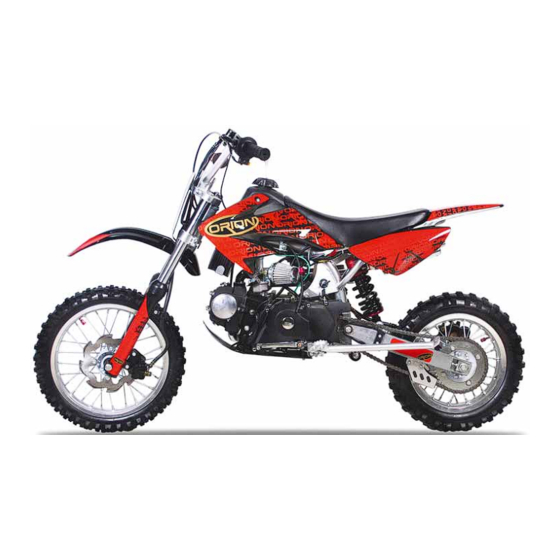
DESCRIPTION GENERAL INFORMATION DESCRIPTION Clutch lever NOTE: Engine stop switch The machine you have purchased may differ Front brake lever slightly from those shown in the following. Throttle grip Designs and specifications are subject to Fuel tank cap change without notice. Engine start switch Fuel tank Air filter... -
Page 8: Machine Identification
MACHINE IDENTIFICATION MACHINE IDENTIFICATION There are two significant reasons for knowing the serial number of your machine: 1. When ordering parts, you can give the number to your dealer for positive identification of the model you own. 2. If your machine is stolen, the authorities will need the number to search for and identify your machine. -
Page 9: Important Information
IMPORTANT INFORMATION IMPORTANT INFORMATION PREPARATION FOR REMOVAL AND DISASSEMBLY 1. Remove all dirt, mud, dust, and foreign material before removal and disassem- bly. When washing the machine with high pressured water, cover the parts follows. Silencer exhaust port Side cover air intake port 2. - Page 10 IMPORTANT INFORMATION GASKETS, OIL SEALS AND O-RINGS 1. All gaskets, oil seals, and O-rings should be replaced when an engine is over- hauled. All gasket surfaces, oil seal lips, and O-rings must be cleaned. 2. Properly oil all mating parts and bearings during reassembly.
-
Page 11: Checking Of Connection
CHECKING OF CONNECTION CHECKING OF CONNECTION Dealing with stains, rust, moisture, etc. on the connector. 1. Disconnect: Connector 2. Dry each terminal with an air blower. 3. Connect and disconnect the connector two or three times. 4. Pull the lead to check that it will not come off. -
Page 12: Special Tools
SPECIAL TOOLS SPECIAL TOOLS The proper special tools are necessary for complete and accurate tune-up and assembly. Using the correct special tool will help prevent damage caused by the use of improper tools or improvised techniques. The shape and part number used for the special tool differ by country, so two types are provided. -
Page 13: Control Functions
CONTROL FUNCTIONS CONTROL FUNCTIONS ENGINE STOP SWITCH The engine stop switch is located on the left handlebar. Continue pushing the engine stop switch till the engine comes to a stop. CLUTCH LEVER The clutch lever is located on the left han- dlebar;... - Page 14 CONTROL FUNCTIONS FRONT BRAKE LEVER The front brake lever is located on the right handlebar. Pull it toward the handlebar to acti- vate the front brake. REAR BRAKE PEDAL The rear brake pedal is located on the right side of the machine. Press down on the brake pedal to activate the rear brake.
-
Page 15: Engine
GENERAL SPECIFICATIONS SPECIFICATIONS AGB-21G Dimensions: l l a , 1, l l a l l a Minimum ground clearance 260 mm Basic weight: 66kg l i o l l u Engine: Air cooled 4-stroke n i l n i l n i l 3.67... -
Page 16: Chassis
GENERAL SPECIFICATIONS Oil capacity: Engine oil With oil filter replacement 0.85 L l i f Fuel: n i l research octane number of 90 or higher. Premium gasoline y t i Carburetor: Z26-5K JINGKE Spark plug: A7RTC/NGK l p i Transmission: Primary reduction system Gear... -
Page 17: Electrical
GENERAL SPECIFICATIONS Brake: Suspension: n i l Shock absorber: l i o Wheel travel: Electrical: 2 - 3... -
Page 18: Maintenance Specifications
MAINTENANCE SPECIFICATIONS ENGINE Cylinder head: - - - Cylinder: ---- - - - Camshaft: ) t f - - - Camshaft cap inside diameter ---- 32.009 ~ 32.034 mm Camshaft outside diameter ---- 31.963 ~ 31.979 mm - t f Cam dimensions Intake “A”... - Page 19 MAINTENANCE SPECIFICATIONS Timing chain: Timing chain type / No. of links 90T/90 ---- c i t - - - Valve, valve seat, valve guide: Valve clearance (cold) 0.02 ~ 0.04 mm ---- 0.02 ~ 0.04 mm ---- Valve dimensions: Head Diameter Face Width Seat Width Margin Thickness...
- Page 20 MAINTENANCE SPECIFICATIONS i l t - - - Valve seat width 0.8 ~ 1.2 mm 1.6 mm 0.8 ~ 1.2 mm 1.6 mm Valve spring: 35.55 mm 34.0 mm Set length (valve closed) 22.45 mm ---- 25.45 mm ---- Compressed force e l l ---- 105 ~ 129 N at 25.45 mm...
- Page 21 MAINTENANCE SPECIFICATIONS Piston pin bore inside diameter 14.002 ~ 14.013 mm 14.04 mm Piston pin outside diameter 13.994 ~ 14.000 mm 13.98 mm Piston rings: Top ring: - - - Dimensions (B 2.00mm ---- e l l 0.60 mm Side clearance (installed) 0.040 ~ 0.080 mm 0.12 mm 2nd ring:...
- Page 22 MAINTENANCE SPECIFICATIONS Clutch: t c i 2.7 mm y t i - - - - - - y t i - - - - - - y t i - - - ---- ---- - - - Shifter: t f i - - - - - - Kickstarter:...
-
Page 23: Regular Inspection And Adjustments
MAINTENANCE INTERVALS REGULAR INSPECTION AND ADJUSTMENTS MAINTENANCE INTERVALS The following schedule is intended as a general guide to maintenance and lubrication. Bear in mind that such factors as weather, terrain, geographical location, and individual usage will alter the required maintenance and lubrication intervals. If you are a doubt as to what intervals to follow in maintaining and lubricating your machine, consult your dealer. -
Page 24: Maintenance Intervals
MAINTENANCE INTERVALS Every Every After Every As re- third fifth Item Remarks break-in race quired 500 km) 1,000 km) SHIFT FORK, SHIFT CAM, GUIDE BAR Inspect Inspect wear ROTOR NUT Retighten EXHAUST PIPE, SILENCER, PRO- TECTOR Inspect and retighten Clean Replace * Whichever comes first CRANK... - Page 25 MAINTENANCE INTERVALS Every Every After Every As re- third fifth Item Remarks break-in race quired 500 km) 1,000 km) FRONT FORKS Inspect and adjust Replace oil Replace oil seal FRONT FORK OIL SEAL AND DUST SEAL Clean and lube REAR SHOCK ABSORBER (After Inspect and adjust rain ride)
- Page 26 PRE-OPERATION INSPECTION AND MAINTENANCE PRE-OPERATION INSPECTION AND MAINTENANCE Before riding for break-in operation, practice or a race, make sure the machine is in good operating condition. Before using this machine, check the following points. GENERAL INSPECTION AND MAINTENANCE Check that a fresh gasoline is filled in the fuel tank. Check the Fuel fuel line for leakage.
-
Page 27: Clutch Adjustment
CLUTCH ADJUSTMENT CLUTCH ADJUSTMENT 1. Check: Clutch lever free play Out of specification Adjust. Clutch lever free play 5 ~ 10 mm 2. Adjust: Clutch lever free play Clutch lever free play adjustment steps: Loosen the locknuts Adjust the free play by changing their tightening position. -
Page 28: Throttle Cable Adjustment
THROTTLE CABLE ADJUSTMENT/ THROTTLE LUBRICATION THROTTLE LUBRICATION 1. Remove: Screw (throttle grip cap) 2. Apply: Lithium soap base grease On the throttle cable end 3. Install: Screw (throttle grip cap) 4 Nm (0.4 m · kg) AIR FILTER REPLACE NOTE: Proper air filter maintenance is the biggest key to preventing premature engine wear and damage. -
Page 29: Engine Oil Level Inspection
ENGINE OIL LEVEL INSPECTION 2. Install: Fitting Screw 5 Nm (0.5 m · kg) ENGINE OIL LEVEL INSPECTION 1. Start the engine, warm it up for several minutes, and then turn off the engine and wait for five minutes. 2. Place the machine on a level place and hold it up on upright position by placing the suitable stand under the engine. - Page 30 ENGINE OIL LEVEL INSPECTION 4. Inspect: Oil level Oil level should be between maximum and minimum marks. Oil level is low Add oil to proper level. NOTE: When inspecting the oil level, do not screw the oil tank cap into the oil tank. Insert the gauge lightly.
-
Page 31: Engine Oil Replacement
ENGINE OIL REPLACEMENT ENGINE OIL REPLACEMENT 1. Start the engine and warm it up for sev- eral minutes, and then turn off the engine and wait for five minute. 2. Place the machine on a level place and hold it on upright position by placing the suitable stand under the engine. -
Page 32: Pilot Screw Adjustment
PILOT SCREW ADJUSTMENT ENGINE IDLING SPEED ADJUSTMENT PILOT SCREW ADJUSTMENT 1. Adjust: Pilot screw Adjustment steps: NOTE: To optimize the fuel flow at a smaller throttle opening, each machine’s pilot screw has been individually set at the factory. Before adjusting the pilot screw, turn it in fully and count the number of turns. - Page 33 CHASSIS/BRAKE SYSTEM AIR BLEEDING CHASSIS BRAKE SYSTEM AIR BLEEDING WARNING Bleed the brake system if: The system has been disassembled. A brake hose has been loosened or removed. The brake fluid is very low. The brake operation is faulty. A dangerous loss of braking performance may occur if the brake system is not prop- erly bleed.
-
Page 34: Front Brake Adjustment
FRONT BRAKE ADJUSTMENT REAR BRAKE ADJUSTMENT NOTE: If bleeding is difficult, it may be necessary to let the brake fluid system stabilize for a few hours. Repeat the bleeding procedure when the tiny bubbles in the system have disap- peared. j. - Page 35 FRONT BRAKE PAD INSPECTION AND REPLACEMENT FRONT BRAKE PAD INSPECTION AND REPLACEMENT 1. Inspect: Brake pad thickness A Out of specification Replace as a set. Brake pad thickness: 4.0 mm <Limit>: 1.0 mm 2. Replace: Brake pad Brake pad replacement steps: Remove Bolt 1 and 2 Loosen the Caliper Remove Bolt 3 and 4...
- Page 36 REAR BRAKE PAD INSPECTION AND REPLACEMENT REAR BRAKE PAD INSPECTION AND REPLACEMENT 1. Inspect: Brake pad thickness A Out of specification Replace as a set. Brake pad thickness: 4 mm <Limit>: 1.0 mm 2. Replace: Brake pad Brake pad replacement steps: Remove the Screw 1 and 2.
- Page 37 REAR BRAKE PAD INSPECTION AND REPLACEMENT CAUTION: Do not reuse the drained brake fluid. Tighten the bleed screw 1 and 2. Bleed screw 1 and 2: 18 Nm (1.8m Nut 3 (brake caliper): 20 Nm (2.0m 3. Inspect: Brake fluid level Refer “BRAKE FLUID...
- Page 38 SPROCKETS INSPECTION/DRIVE CHAIN INSPECTION SPROCKETS INSPECTION 1. Inspect: Sprocket teeth a Excessive wear Replace. NOTE: Replace the drive sprocket, rear wheel sprocket and drive chain as a set. DRIVE CHAIN INSPECTION 1. Remove: Master link clip Joint Drive chain 2. Clean: Drive chain Place it in kerosene, and brush off as much dirt as possible.
-
Page 39: Drive Chain Slack Adjustment
DRIVE CHAIN SLACK ADJUSTMENT 5. Install: Drive chain Joint Master link clip CAUTION: Be sure to install the master link clip to the direction as shown. Turning direction 6. Lubricate: Drive chain Drive chain lubricant: SAE 10W-30 motor oil or suit- able chain lubricants DRIVE CHAIN SLACK ADJUSTMENT 1. -
Page 40: Front Fork Inspection
FRONT FORK INSPECTION 3. Adjust: Drive chain slack Drive chain slack adjustment steps: Loosen the axle nut and locknuts Adjust the drive chain slack by turning the adjusters To tighten Turn the adjuster coun- terclockwise. To loosen Turn the adjuster clock- wise and push wheel forward. -
Page 41: Electrical System
CHECKING THE BATTERY ELECTRICAL SYSTEM CHECKING THE BATTERY WARNING Batteries generate explosive hydrogen gas and contain electrolyte which is made of poisonous and highly caustic sulfuric acid. Therefore, always follow these preventive measures: Wear protective eye gear when handling or working near batteries. - Page 42 CHECKING THE BATTERY CAUTION: Add only distilled water. Tap water contains minerals which are harmful to the battery. 3. Charge: battery Battery charging amperage and time 0.4 amps/10 hrs WARNING Do not quick charge a battery. CAUTION: To ensure maximum performance, always charge a new battery before using it.
- Page 43 CHECKING THE FUSES REAR SHOCK ABSORBER INSPECTION CHECKING THE FUSE The following procedure applies to all of the fuses. CAUTION: To avoid a short circuit, always turn the main switch to “OFF” when checking or replacing a fuse. Check: fuse a.
- Page 44 REAR SHOCK ABSORBER SPRING PRELOAD ADJUSTMENT REAR SHOCK ABSORBER SPRING PRELOAD ADJUSTMENT 1. Elevate the rear wheel by placing the suitable stand under the engine. 2. Remove: Rear frame 3. Loosen: Locknut 4. Adjust: Spring preload By turning the adjuster Stiffer Increase the spring preload.
- Page 45 TIRE PRESSURE CHECK/SPOKES INSPECTION AND TIGHTENING/WHEEL INSPECTION TIRE PRESSURE CHECK 1. Measure: Tire pressure Out of specification Adjust. Standard tire pressure: 130 kPa ( 1.3 kgf/cm ) NOTE: Check the tire while it is cold. Loose bead stoppers allow the tire to slip off its position on the rim when the tire pressure is low.
- Page 46 STEERING HEAD INSPECTION AND ADJUSTMENT 2. Inspect: Bearing free play Exist play Replace. STEERING HEAD INSPECTION AND ADJUSTMENT 1. Elevate the front wheel by placing a suit- able stand under the engine. 2. Check: Steering stem Grasp the bottom of the forks and gen- tly rock the fork assembly back and forth.
- Page 47 STEERING HEAD INSPECTION AND ADJUSTMENT Tighten the steering ring nut using steering nut wrench NOTE: Apply the lithium soap base grease on the thread of the steering stem. Set the torque wrench to the steering nut wrench so that they form a right angle. Steering ring nut (initial tightening): 30 Nm ( 3 m •...
- Page 48 ELECTRICAL/SPARK PLUG INSPECTION ELECTRICAL SPARK PLUG INSPECTION 1. Remove: Spark plug 2. Inspect: Electrode Wear/damage Replace. Insulator color Normal condition is a medium to light tan color. Distinctly different color Check the engine condition. NOTE: When the engine runs for many hours at low speeds, the spark plug insulator will become sooty, even if the engine and carburetor are in good operating condition.
-
Page 49: Ignition Timing Check
IGNITION TIMING CHECK IGNITION TIMING CHECK 1. Remove: Timing mark accessing screw 2. Check: Ignition timing Checking steps: Start the engine and let it warm up. Let the engine run at the specified speed. Engine speed: 1,400 ~ 1,600 r/min Visually check the stationary pointer within the firing range on the rotor. - Page 50 ENGINE SEAT, FUEL TANK AND SIDE COVERS SEAT, FUEL TANK AND SIDE COVERS Order Job / Part name Q’ty Remarks Remove the parts in the order listed. LEFT TANK COVER RIGHT TANK COVER SEAT LEFT FENDER PLATE RIGHT FENDER PLATE TAIL FENDER FUEL TANK FUEL CAP...
- Page 51 SEAT, FUEL TANK AND SIDE COVERS REMOVAL POINTS Fuel Tank , Side covers and Seat Remove: Bolt for Tank Cover Seat Bolt Bolt for Fuel Tank Fuel Tank Screw for Tank Cover and Seat Left Tank Cover Right Tank Cover Screw for Fender plate Left Fender plate Right Fender plate...
-
Page 52: Exhaust Pipe And Silencer
EXHAUST PIPE AND SILENCER EXHAUST PIPE AND SILENCER Order Job / Part name Q’ty Remarks Remove the parts in the order listed. BOLT HOOP RUBBER MAT NUT M6×14 EXHAUST MUFFLER EXHAUST PIPE SEAL For installation, reverse the removal procedure. 4 - 3... - Page 53 EXHAUST PIPE AND SILENCER INSPECTION Silencer and exhaust pipe 1. Inspect: Gasket Damage Replace. ASSEMBLY AND INSTALLATION Silencer and exhaust pipe 1. Install: Gasket Exhaust muffler (exhaust pipe) 15 Nm (1.5 m • kg) 2. Install: Washer Bolt (silencer) 25 Nm (2.5 m • kg) NOTE: First, temporarily tighten the Nut (exhaust...
- Page 54 CRBURETOR & AIR-FITER CRBURETOR & AIR-FITER Order Job / Part name Q’ty Remarks Remove the parts in the order listed. SCREW FOR AIR-FITER CLAMP AIR-FITER CRBURETOR GASKET,HEAT INSULATING, CRBURETOR O-RING INLET PIPE O-RING GASKET For installation, reverse the removal procedure. 4 - 5...
-
Page 55: Carburetor Disassembly
CARBURETOR DISASSEMBLY CARBURETOR DISASSEMBLY Order Job / Part name Q’ty Remarks Remove the parts in the order listed. UPPER COVER GASKET,UPPER COVER RETURN SPRING,AIR THROTTLE V-CLIP E-CIRCLIP NEEDLE,JET AIR THROTTLE O-RING ADJUSTING SCREW,AIR THROTTLE SPRING,ADJUSTING SCREW O-RING WASHER ADJUSTING SCREW SPRING IDLE FOAM JET MAIN JET,OIL MAIN JET,FOAM... - Page 56 CARBURETOR DISASSEMBLY CARBURETOR DISASSEMBLY Order Job / Part name Q’ty Remarks Remove the parts in the order listed. FLOAT COMP NEEDLE VALVE,CARBURETOR FLOAT HOOK,NEEDLE VALVE FLOAT PIN GASKET,FLOAT CHAMBER DRAIN SCREW O-RING SCREW UNIT,FLOAT CHAMPER PIPE CLIP HOSE For installation, reverse the removal procedure. 4 - 7...
- Page 57 CARBURETOR INSPECTION Carburetor 1. Inspect: Carburetor body Contamination → Clean. NOTE: Use a petroleum based solvent for cleaning. Blow out all passages and jets with com- pressed air. Never use a wire. 2. Inspect: Adjust Screw,Mixture Idle Jet Main Measuring Hole and Main Nozzi Main Jet Drain Screw Damage →...
- Page 58 SPROCKET REPLACEMENT SPROCKET REPLACEMENT Order Job / Part name Q’ty Remarks Remove the parts in the order listed. COVER,L.RR.CRANKCASE INITIATIVE CHAIN DRIVER RIVET PLANK DRIVING GEAR SHIFT PEDAL GUAGE OIL LEVER KICK STARTER SPARK PLUG CAP ENGINE SKID PLATE SIDE STAND RIGHT FOOT PAGS LEFT FOOT PEGS BRACKET FOR PEDAL...
-
Page 59: Cylinder Head
CYLINDER HEAD CYLINDER HEAD Order Job / Part name Q’ty Remarks Remove the parts in the order listed. Spark plug Bolt M6 x 110 Cylinder cover L / Gasket Timing driven sprocket Valve cover / O-ring Valve cover / O-ring Cylinder cover Gasket,cylinder cover Cylinder head... - Page 60 CYLINDER HEAD REMOVING THE CYLINDER HEAD 1. Remove: Long Bolt A Nut B 2. Align: “I” mark a on the generator rotor (with the stationary pointer b on the crankcase cov- a. Turn the primary pulley counterclockwise. b. When the piston is at TDC on the compres- sion stroke, align the “I”...
- Page 61 CYLINDER HEAD 5 Remove Chain Tensioner Bolt 1 Washer 2 Spring Chain Tensioner Push Road Chain Tensioner Push Road Assembly NOTE: To prevent the timing chain from falling into the crankcase, fasten it with a wire a . While holding the generator rotor bolt with a wrench, remove the bolt.
- Page 62 CYLINDER HEAD 6. Remove: cylinder head NOTE: Loosen the nuts in the proper sequence. Loosen each nut 1/2 of a turn at a time. After all of the nuts are fully loosened, remove them. CHECKING THE CYLINDER HEAD 1. Eliminate: combustion chamber carbon deposits (with a rounded scraper) NOTE:...
- Page 63 CYLINDER HEAD CHECKING THE TIMING CHAIN TENSIONER 1. Check: timing chain tensioner Cracks/damage Replace. CHECKING THE TAPPET COVERS AND CAMSHAFT SPROCKET COVER The following procedure applies to both of the tappet covers and O-rings. 1. Check: tappet cover camshaft sprocket cover O-ring Damage/wear Replace the defective...
- Page 64 CYLINDER HEAD INSTALLING THE CAMSHAFT SPROCKET 1. Align: “I” mark on the generator rotor (with the mark on the generator rotor cover) a. Turn the crankshaft counterclockwise. b. When the piston is at TDC on the compres- sion stroke, align the “I” mark a on the gen- erator rotor with the mark b on the genera- tor rotor cover.
- Page 65 CAMSHAFT /VALVES AND VALVE SPRINGS CAMSHAFT /VALVES AND VALVE SPRINGS Order Job / Part name Q’ty Remarks Remove the parts in the order listed. RIGHT COVER,CYLINDER HEAD GASKET SHAFT,VALVE RROCKER ARM ADJUSTING NUT ADJUSTING SCREW VALVE RROCKER ARM CAM SHAFT VALVE COTTER PETAINER,VALVE SPRING VALVE INNER SPRING...
- Page 66 CAMSHAFT /VALVES AND VALVE SPRINGS REMOVING THE ROCKER ARMS AND CAM- SHAFT 1. Loosen: locknuts 1 adjusting screws 2 2. Remove: intake rocker arm shaft exhaust rocker arm shaft intake rocker arm exhaust rocker arm 3. Remove: camshaft 1 CHECKING THE CAMSHAFTS 1.
- Page 67 CAMSHAFT /VALVES AND VALVE SPRINGS 2 Measure: camshaft lobe dimensions A Out of specification Replace the cam- shaft. Camshaft lobe dimension limit Intake 26.30 mm Exhaust 26.00 mm 3. Check: camshaft oil passage Obstruction Blow out with compressed air. CHECKING THE ROCKER ARMS AND ROCKER ARM SHAFTS The following procedure applies to all of the rocker arms and rocker arm shafts.
- Page 68 CAMSHAFT /VALVES AND VALVE SPRINGS 6. Calculate: rocker-arm-to-rocker-arm-shaft clearance NOTE: Calculate the clearance by subtracting the rock- er arm shaft outside diameter from the rocker arm inside diameter. Out of specification Replace the defective part(-s). Rocker-arm-to-rocker-arm-shaft clearance 0.005 0.035 mm INSTALLING THE CAMSHAFT AND ROCK- ER ARMS 1.
- Page 69 CAMSHAFT /VALVES AND VALVE SPRINGS REMOVING THE VALVES The following procedure applies to all of the valves and related components. NOTE: Before removing the internal parts of the cylin- der head (e.g., valves, valve springs, valve seats), make sure that the valves properly seal. 1.
- Page 70 CAMSHAFT /VALVES AND VALVE SPRINGS CHECKING THE VALVES AND VALVE GUIDES The following procedure applies to all of the valves and valve guides. 1. Measure: valve-stem-to-valve-guide clearance Valve-stem-to-valve-guide clearance = Valve guide inside diameter a – Valve stem diameter b Out of specification Replace the valve guide.
- Page 71 CAMSHAFT /VALVES AND VALVE SPRINGS 3. Eliminate: carbon deposits (from the valve face and valve seat) 4. Check: valve face Pitting/wear Grind the valve face. valve stem end Mushroom shape or diameter larger than the body of the valve stem Replace the valve.
- Page 72 CAMSHAFT /VALVES AND VALVE SPRINGS a. Apply Mechanic’s blueing dye (Dykem) 1 onto the valve face. b. Install the valve into the cylinder head. c. Press the valve through the valve guide and onto the valve seat to make a clear pattern. d.
- Page 73 CAMSHAFT /VALVES AND VALVE SPRINGS e. Apply a fine lapping compound to the valve face and repeat the above steps. f. After every lapping procedure, be sure to clean off all of the lapping compound from the valve face and valve seat. g.
- Page 74 CAMSHAFT /VALVES AND VALVE SPRINGS INSTALLING THE VALVES The following procedure applies to all of the valves and related components. 1. Deburr: valve stem end (with an oil stone) 2. Lubricate: valve stem oil seal (with the recommended lubricant) Recommended lubricant Molybdenum disulfide oil 3.
-
Page 75: Cylinder And Piston
CYLINDER AND PISTON CYLINDER AND PISTON Order Job / Part name Q’ty Remarks Remove the parts in the order listed. PIN SHAFT,GUIDEROLLER CAM CHAIN GUIDE ROLLER CYLINDER BLOCK GASKET,CYLINDER BLOCK DOWEL PIN RECTANGLE RING CIRCLIP,PISTON PIN PISTON PIN PISTON PISTON RING For installation, reverse the removal procedure. - Page 76 CYLINDER AND PISTON REMOVING THE PISTON AND PISTON RINGS 1. Remove: piston pin circlip 1 piston pin 2 piston 3 NOTE: Before removing the piston pin circlip, cover the crankcase opening with a clean towel or rag to prevent the circlip from falling into the crank- case cavity.
- Page 77 CYLINDER AND PISTON b. If out of specification, rebore or replace the cylinder, and replace the piston and piston rings as a set. c. Measure piston skirt diameter “P” with the micrometer. 1 7.0 mm from the bottom edge of the piston. Piston size “P”...
- Page 78 CYLINDER AND PISTON 2. Install: piston ring (into the cylinder) NOTE: Level the piston ring in the cylinder with the pis- ton crown as shown. a 5.0 mm 3. Measure: piston ring end gap Out of specification Replace the piston ring.
- Page 79 CYLINDER AND PISTON Piston-pin-to-piston clearance = Piston pin bore size b – Piston pin outside diameter a Piston-pin-to-piston clearance 0.002 0.019 mm INSTALLING THE PISTON AND CYLINDER 1. Install: top ring 1 2nd ring 2 upper oil ring rail oil ring expander lower oil ring rail 5 NOTE: Be sure to install the piston rings so that the...
- Page 80 CYLINDER AND PISTON 5. Offset: piston ring end gaps a Top ring b Lower oil ring rail c Upper oil ring rail d 2nd ring 6. Install: cylinder 1 NOTE: While compressing the piston rings with one hand, install the cylinder with the other hand. Pass the timing chain and timing chain guide (exhaust side) through the timing chain cavity.
- Page 81 CLUTCH CLUTCH Order Job / Part name Q’ty Remarks Remove the parts in the order listed. DECORATE COVER,R CRANK CASE COVER GASKET,DECORATE COVER CLUTCHLEVER PIN CLUTCHLEVER ASSY CLUTCH CAM SHAFT SPRING O-RING CLUTCH SHIFTING PLATE CLUTCH PRESSURE PLATE OIL SEAL OIL SEAL R ,CRANK CASE COVER GASKET,R ,CRANK CASE COVER...
- Page 82 CLUTCH CLUTCH Order Job / Part name Q’ty Remarks Remove the parts in the order listed. GASKET,END COVER WASHER THURST WASHER CLUTCH ASSY DRIVER GEAR SLEEVE BUSH CIRCLIP DRIVEN GEAR CAM For installation, reverse the removal procedure. 4 - 33...
- Page 83 CLUTCH CLUTCH Order Job / Part name Q’ty Remarks Remove the parts in the order listed. CIRCLIP PLATE CLUTCH DRIVE FRICTION PLATE CLUTCH CENTER SLEEVE DRIVE PLATE CLUTCH CUSHION SPRING CLUTCH SPRING CLUTCH OUTER CASE For installation, reverse the removal procedure. 4 - 34...
- Page 84 CLUTCH REMOVING THE CLUTCH 1. Remove: Screw 2. Straighten the lock washer tab 3. Remove: clutch boss nut washer NOTE: While holding the clutch boss with the univer- sal clutch holder , loosen the clutch boss nut. 4. Remove: snap spring CHECKING THE FRICTION PLATES The following procedure applies to all of the fric- tion plates.
- Page 85 CLUTCH 2. Measure: clutch plate warpage (with a surface plate and thickness gauge Out of specification Replace the clutch plates as a set. Clutch plate warpage limit Less than 0.1 mm CHECKING THE CLUTCH SPRINGS The following procedure applies to all of the clutch springs.
- Page 86 CLUTCH INSTALLING THE CLUTCH ASSY 1. Install: put the clutch spring into the clutch outer case. put the drive plate into the clutch outer case. 2. Lubricate: friction plates upper plates (with the recommended lubricant) Recommended lubricant Engine oil 3. Install: friction plates upper plates NOTE:...
- Page 87 CLUTCH CHECKING THE CLUTCH PUSH RODS 1. Check: oil tube 1 oil thimble spring 2 oil thimble 3 Cracks/damage/wear Replace the de- fective part(-s). 2. Measure: oil thimble spring free length Out of specification Replace the oil thim- ble spring. Oil thimble spring free length 17.5 mm INSTALLING THE CLUTCH...
- Page 88 CLUTCH 4. Install: oil tube 1 oil thimble spring 2 oil thimble 3 screw 6 Nm (0.6 m • kg) 5. Check clutch assy NOTE: Make sure that the teeth on the lock washer are correctly aligned with the grooves on the clutch boss.
-
Page 89: Oil Pump
OIL PUMP OIL PUMP Order Job / Part name Q’ty Remarks Remove the parts in the order listed. OIL PUMP OIL FILTER SCREEN GEAR For installation, reverse the removal procedure. 4 - 40... - Page 90 OIL PUMP REMOVING THE OIL PUMP 1. Remove: Screw 2. Remove: gasket of oil pump gear of oil pump NOTE: Remove the gasket of oil pump and check the state.Replace if worn or if reuse if questionable. 3. Check: Remove the oil pump and inspect oil way for smoothness.clean oil way as necessary.
- Page 91 MAGNETO AND STARTER GEAR MAGNETO AND STARTER GEAR Order Job / Part name Q’ty Remarks Remove the parts in the order listed. FRONT COVER, LEFT CRANKCASE GASKET, LEFT CRANKCASE STATOR , MAGNETO COTOR , MAGNETO CIRCLIP 10 DRIVEN SPROCKET, STARTING MOTOR DRIVE SPROCKET, STARTING MOTOR...
- Page 92 MAGNETO AND STARTER GEAR REMOVING THE GENERATOR ROTOR 1. Remove: bolt 1 (magneto) NOTE: Loosen the bolt (generator rotor) 1 while holding the rotor with a sheave holder 2 . Do not allow the sheave holder to touch the projection on the rotor. 2.
- Page 93 MAGNETO AND STARTER GEAR 2. Check: starter clutch operation a. Hold the starter clutch. b. When turning the starter clutch gear clock- wise a , the starter clutch and the starter clutch gear should engage. If the starter clutch gear and starter clutch do not engage, the starter clutch is faulty and must be replaced.
- Page 94 MAGNETO AND STARTER GEAR INSTALLING THE GENERATOR ROTOR 1. Install: starter wheel gear woodruff key 2. Install: starting motor drive chain drive gear cirlip bolt chain protect plate 3. Install: generator rotor 1 NOTE: Clean the tapered portion of the crankshaft and the rotor hub.
- Page 95 CAM CHAIN-TENSIOR CAM CHAIN-TENSIOR Order Job / Part name Q’ty Remarks Remove the parts in the order listed. CLIP, VOLTAGE WIRE LOWER PAN, OIL INSULATING O-RING OIL SEAL BOLT M14×1.5 WASHER SPRING, CHAIN TENSIONER PUSH CHAIN TENSIONER PUSH ROD TIGHTENING ROD HEAD TIMING CHAIN TIGHTENING ARM SHAFT TIGHTENING ARM...
- Page 96 CAM CHAIN-TENSIOR CAM CHAIN TENSIOR 1. Remove: bolt of cam chain tensior roller of cam chain tensior 2 cam chain 3 2. Check: aluminium washer Pitting/Wear/Damage Replace. spring of chain tensior push rod Pitting/Wear/Damage Replace. INSTALLING THE CAM CHAIN TENSIOR 1.
- Page 97 CRANKSHAFT AND GEARSHIFT ARM CRANKSHAFT AND GEARSHIFT ARM Order Job / Part name Q’ty Remarks Remove the parts in the order listed. BOLT, LOCATING PLATE LOCATING PLATE GROUP RETURN SPRING, LOCATING PLATE RETURN SPRING, GEARSHIFT LEVER BUSH GEARSHIFT LEVER BODY ASSY TENSION SPRING, GEARSHIFT LEVER STOP PLATE...
- Page 98 CRANKSHAFT AND GEARSHIFT ARM CRANKSHAFT AND GEARSHIFT ARM Order Job / Part name Q’ty Remarks Remove the parts in the order listed. CONTACT, GEAR INDICATION CYLINDER STUD BOLT B M7 X 204 CYLINDER STUD BOLT A M7 X 212 OIL DRAIN PLUG M12×1.5 WASHER 12.5×1.5×20 BOLT M6×65 BOLT M6×60...
- Page 99 CRANKSHAFT AND GEARSHIFT ARM DISASSEMBLING THE CRANKCASE 1. Gearshift arm Remove: bolt of locating plate bolt of locating plate 2. Remove: cirlip spring spring seat 4 - 50...
- Page 100 CRANKSHAFT DISASSEMBLING THE CRANKCASE 1. Remove: crankcase bolts NOTE: Loosen each bolt 1/4 of a turn at a time, in stages and in a crisscross pattern. After all of the bolts are fully loosened, remove them. Loosen the bolts in decreasing numerical or- der (refer to the numbers in the illustration).
- Page 101 CRANKSHAFT CRANKSHAFT Order Job / Part name Q’ty Remarks Remove the parts in the order listed. TIMING DRIVE SPROCKET BEARING (6205) BEARING (6205) ROLLER BEARING JOINT RED LEFT CRANKSHAFT RIGHT CRANKSHAFT For installation, reverse the removal procedure. 4 - 52...
- Page 102 CRANKSHAFT CHECKING THE CRANKSHAFT AND CON- NECTING ROD 1. Measure: crankshaft runout Out of specification Replace the crank- shaft, bearing or both. NOTE: Turn the crankshaft slowly. Crankshaft runout Less than 0.03 mm 2. Measure: big end axial clearance Out of specification Replace the big end bearing, crankshaft pin, or connecting rod.
- Page 103 CRANKSHAFT CHECKING THE BEARINGS AND OIL SEALS 1. Check: bearings Clean and lubricate the bearings, then rotate the inner race with your finger. Rough movement Replace. 2. Check: oil seals Damage/wear Replace. CHECKING THE TIMING CHAIN, CAM- SHAFT SPROCKET, AND TIMING CHAIN GUIDES 1.
- Page 104 CRANKSHAFT INSTALLING THE CRANKSHAFT 1. Install: crankshaft 1 CAUTION: To avoid scratching the crankshaft and to ease the installation procedure, apply grease onto the oil seal lips and apply en- gine oil onto each bearing. ASSEMBLING THE CRANKCASE 1. Thoroughly clean all the gasket mating sur- faces and crankcase mating surfaces.
- Page 105 TRANSMISSION DEVICE,SHIFT DRUM ,GEAR FORKS TRANSMISSION DEVICE,SHIFT DRUM ,GEAR FORKS Order Job / Part name Q’ty Remarks Remove the parts in the order listed. RATCHET SPRING PLATE WASHER 17 CIRCLIP SPRING RATCHET SPRING BASE STARING RATCHET WHEEL CIRCLIP WASHER STARING GEAR SPRING SHAFE BEARING 14-1...
- Page 106 TRANSMISSION DEVICE,SHIFT DRUM ,GEAR FORKS TRANSMISSION DEVICE,SHIFT DRUM ,GEAR FORKS Order Job / Part name Q’ty Remarks Remove the parts in the order listed. MAINSHAFT COUNTERSHAFT BEARING 6203 BEARING 6201 BEARING 6001 BEARING 6203 OIL SEAL 17X29X5 For installation, reverse the removal procedure. 4 - 57...
- Page 107 TRANSMISSION DEVICE,SHIFT DRUM ,GEAR FORKS REMOVING THE TRANSMISSION 1. Loosen: screw 1 2. Remove: screw 1 contact ,gear indication 2 3. Remove: drive axle assembly 1 main axle assembly 2 gearshift drum assy 3 Remove them at same the time. 4.Gearshift drum assy dissembly.
- Page 108 TRANSMISSION DEVICE,SHIFT DRUM ,GEAR FORKS CHECKING THE SHIFT FORKS The following procedure applies to all of the shift forks and related components. Check: shift fork cam follower 1 shift fork pawl 2 Bends/damage/scoring/wear Replace the shift fork. CHECKING THE SHIFT DRUM 1.
- Page 109 TRANSMISSION DEVICE,SHIFT DRUM ,GEAR FORKS CHECKING THE TRANSMISSION 1. Measure: main axle runout (with a centering device and dial gauge 1 ) Out of specification Replace the main axle. Main axle runout limit 0.02 mm 2. Measure: drive axle runout (with a centering device and dial gauge 1 ) Out of specification Replace the drive...
- Page 110 TRANSMISSION DEVICE,SHIFT DRUM ,GEAR FORKS INSTALLING THE TRANSMISSION, SHIFT FORKS AND SHIFT DRUM 1. Install: main axle 1 drive axle 2 gearshift drum assy 3 Put them into the crankcase at same the time. 2. Check: shift cam operation Unsmoothy operation Repair.
-
Page 111: Front Wheel And Rear Wheel
FRONT WHEEL AND REAR WHEEL FRONT WHEEL Order Job / Part name Q’ty Remarks Remove the parts in the order listed. NUT(FRONT WHEEL AXLE) FRONT RIM AXLE FRONT TIRE COLLAR FR.WHEEL OIL SEAL BEARING FRONT-BRAKE DISK For installation, reverse the removal procedure. 5 - 1... -
Page 112: Rear Wheel
FRONT WHEEL AND REAR WHEEL REAR WHEEL Order Job / Part name Q’ty Remarks Remove the parts in the order listed. NUT(FRONT WHEEL AXLE) FRONT RIM AXLE CHAIN PULLER REAR WHEEL COLLAR RE.WHEEL DRIVEN SPROKET OIL SEAL BEARING FRONT-BRAKE DISK For installation, reverse the removal procedure. - Page 113 FRONT WHEEL AND REAR WHEEL REMOVAL POINTS Rear wheel 1. Remove: Wheel NOTE: Push the wheel forward and remove the drive chain Wheel bearing (if necessary) 1. Remove: Bearing NOTE: Remove the bearing using a general bearing puller INSPECTION Wheel 1.
- Page 114 FRONT WHEEL AND REAR WHEEL Wheel axle 1. Measure: Wheel axle bends Out of specification → Replace. Use the dial gauge Wheel axle bending limit: 0.5 mm NOTE: The bending value is shown by one half of the dial gauge reading. WARNING Do not attempt to straighten a bent axle.
- Page 115 FRONT WHEEL AND REAR WHEEL ASSEMBLY AND INSTALLATION Front wheel 1. Install: Bearing (left) Middel spacer Bearing (right) Oil seal Collar (left) Collar (right) NOTE: Apply the lithium soap base grease on the bearing and oil seal lip when installing. Use a socket that matches the outside diam- eter of the race of the bearing.
- Page 116 FRONT WHEEL AND REAR WHEEL 5. Install: Wheel axle NOTE: Apply the lithium soap base grease on the wheel axle. 6. Install: Nut (wheel axle) 50Nm (5 m · kg ) 5 - 6...
- Page 117 FRONT WHEEL AND REAR WHEEL Rear wheel 1. Install: Bearing (left) Bearing (right) Middle spacer Oil seal Left Collar Right Collar NOTE: Apply the lithium soap base grease on the bearing and oil seal lip when installing. Install the bearing with seal facing outward. Use a socket that matches the outside diam- eter of the race of the bearing.
- Page 118 FRONT WHEEL AND REAR WHEEL 3. Install: Rear wheel sprocket Bolt (rear wheel sprocket) 25 Nm (2.5m · kg) Washer (rear wheel sprocket) Nut (rear wheel sprocket) NOTE: Tighten the nuts in stage, using a crisscross pattern. 4. Install: Left Collar NOTE: Apply the lithium soap base grease on the oil seal lip.
- Page 119 FRONT WHEEL AND REAR WHEEL 7. Install: Left drive chain puller Wheel axle NOTE: Install the left drive chain puller, and insert the wheel axle from left side. Apply the lithium soap base grease on the wheel axle. 8. Install: Left drive chain puller Bolt (wheel axle) Adujust bolt (wheel axle)
-
Page 120: Front Brake And Rear Brake
FRONT BRAKE AND REAR BRAKE FRONT BRAKE Order Job / Part name Q’ty Remarks Remove the parts in the order listed. FR,CALIPER ASSY. UNION BOLT FR,BRAKE HOSE BRAKE LEVER BRAKE MASTER CYLINDER BRACKET BRAKE MASTER CYLINDER For installation, reverse the removal procedure. 5 - 10... -
Page 121: Rear Brake
FRONT BRAKE AND REAR BRAKE REAR BRAKE Order Job / Part name Q’ty Remarks Remove the parts in the order listed. UNION BOLT. REAR,CALIPER ASSY. REAR,BRAKE HOSE REAR MASTER CYLINDER ASSY REAR.BRAKE PEDAL For installation, reverse the removal procedure. 5 - 11... - Page 122 FRONT WHEEL AND REAR WHEEL REMOVAL POINTS Brake fluid 1. Remove: [Front] Brake master cylinder cap NOTE: Do not remove the diaphragm. [Rear] Brake master cylinder cap NOTE: Do not remove the diaphragm. ı 2. Connect the transparent hose to the bleed screw and place a suitable con- tainer under its end.
- Page 123 FRONT WHEEL AND REAR WHEEL Brake caliper piston 1. Remove: Brake caliper piston Use compressed air and proceed care- fully. WARNING Cover piston with rag and use extreme caution when expelling piston from cylin- der. Never attempt to pry out piston. Caliper piston removal steps: Insert a piece of rag into the brake caliper to lock one brake caliper.
- Page 124 FRONT WHEEL AND REAR WHEEL 2. Inspect: Diaphragm Crack/damage → Replace. 3. Inspect: Brake master cylinder piston Brake master cylinder cup Wear/damage/score marks → Replace brake master cylinder kit. Brake hose 1. Inspect: Brake hose Crack/damage → Replace. 5 - 14...
- Page 125 FRONT WHEEL AND REAR WHEEL ASSEMBLY AND INSTALLATION WARNING All internal parts should be cleaned in new brake fluid only. Internal parts should be lubricated with brake fluid when installed. Front braker caliper 1. Install: Pad support Brake pad Pad pin 2.
- Page 126 FRONT WHEEL AND REAR WHEEL Rear braker caliper 1. Install: Pad support Brake pad Pad pin 2. Install: Brake caliper Right spacer (rear wheel) Nut (rear wheel) 5 - 16...
- Page 127 FRONT WHEEL AND REAR WHEEL Brake master cylinder kit 1. Clean: Brake master cylinder Brake master cylinder kit Clean them with brake fluid. 2. Install: Brake master cylinder cup (primary) Brake master cylinder cup (secondary) To brake master cylinder piston NOTE: Apply the brake fluid on the brake master cyl- inder cup.
- Page 128 FRONT WHEEL AND REAR WHEEL Front brake master cylinder 1. Install: Brake master cylinder Brake master cylinder bracket Bolt (brake master cylinder bracket) 9 Nm ( 0.9 m • kg ) NOTE: Install the bracket so that the arrow mark face upward.
- Page 129 FRONT WHEEL AND REAR WHEEL 9 Nm (0.9 m · kg) Spring Brake pedal Washer Cotter pin NOTE: After installing, check the brake pedal height. Refer to “REAR BRAKE ADJUSTMENT” sec- tion in the CHAPTTER 3 . Front brake hose 1.
- Page 130 FRONT WHEEL AND REAR WHEEL 2. Install: Copper washer Brake hose Union bolt 25 Nm (2.5 m · kg) WARNING Always use new copper washers. Rear brake hose 1. Install: Copper washer Brake hose Union bolt 25 Nm (2.5 m · kg) WARNING Always use new copper washers.
- Page 131 FRONT BRAKE AND REAR BRAKE Brake fluid 1. Fill: Brake fluid Until the fluid level reaches “LOWER” level line . Recommended brake fluid: DOT #3 or DOT #4 WARNING Use only the designated quality brake fluid: otherwise, the rubber seals may deterio- rate, causing leakage and poor brake per- formance.
- Page 132 FRONT BRAKE AND REAR BRAKE 4. Install: [Front] Diaphragm Brake master cylinder cap Screw (brake master cylinder cap) 2 Nm (0.2 m · kg) [Rear] Diaphragm Brake master cylinder cap Bolt (brake master cylinder cap) 2 Nm (0.2 m · kg) CAUTION: ACHTUNG: After installation, while pulling the brake...
- Page 133 STREERING STREERING Order Job / Part name Q’ty Remarks Remove the parts in the order listed. NUT STEERING UPPER M22 WASHER STEEL). STEERING STEM LOCK NUT BEARING ASSY TRIPLE CLAMP(STEERING STEM) ASSY For installation, reverse the removal procedure. 5 - 23...
-
Page 134: Front Fork
FRONT FORK FRONT FORK Order Job / Part name Q’ty Remarks Remove the parts in the order listed. FRONT NUMBER PLATE FRONT FENDER SCREW SCREW . FRONT.FORK ASSY For installation, reverse the removal procedure. 5 - 24... -
Page 135: Front Fork And Steering
FRONT FORK AND STEERING Installation 1. Install: Front fork NOTE: Temporarily tighten the pinch bolts (lower bracket). Do not tighten the pinch bolts (upper bracket) yet. 2. Tighten: Front fork . 4. Tighten: Pinch bolt (upper bracket) 15 Nm (1.5 m · kg) Pinch bolt (lower bracket) 15 Nm (1.5 m ·... - Page 136 FRONT FORK AND STEERING REMOVAL POINTS Steering ring nut 1. Remove: Steering ring nut Use the steering nut wrench WARNING Support the steering stem so that it may not fall down. ı Lower bearing 1. Remove: Lower bearing Use the floor chisel CAUTION: ACHTUNG: Take care not to damage the steering shaft...
- Page 137 FRONT FORK AND STEERING Bearing and ball race 1. Wash the bearings and ball races with a solvent. 2. Inspect: Bearing Ball race Pitting/damage → Replace bearings and ball races as a set. Install the bearing in the ball races. Spin the bearings by hand.
- Page 138 FRONT FORK AND STEERING 4. Install: Steering ring nut 30 Nm (3 m · kg) Tighten the steering ring nut using the steering nut wrench Refer to “STEERING HEAD INSPEC- TION AND ADJUSTMENT” section in the CHAPTER 3. 5. Check the steering stem by turning it lock to lock.
- Page 139 FRONT FORK AND STEERING 9. Tighten: Pinch bolt (upper bracket) 15 Nm (1.5 m · kg) Pinch bolt (lower bracket) 15 Nm (1.5 m · kg) CAUTION: ACHTUNG: Tighten the lower bracket to specified torque. If torqued too much, it may cause the front fork to malfunction.
- Page 140 HANDLEBAR HANDLEBAR Order Job / Part name Q’ty Remarks Remove the parts in the order listed. CROSS BAR COVER CROSS BAR FOAM. GRIP .R THROTTLE HOUSEING THROTTLE CABLE GRIP .L START SWITCH ASSY CLUTCH LEVER ASSY. CLUTCH CABLE ASSY SCREW WITH NUTM8X80 RISER SET FOR HANDLEBAR HANDLEBAR RISER SET FOR HANDLEBAR...
- Page 141 HANDLEBER REMOVAL POINTS Brake master cylinder 1. Remove: Brake master cylinder bracket Brake master cylinder CAUTION: ACHTUNG: Do not let the brake master cylinder hang on the brake hose. Keep the brake master cylinder cap side horizontal to prevent air from coming in. Grip 1.
- Page 142 HANDLEBER ASSEMBLY AND INSTALLATION Handlebar 1. Install: Handlebar Handlebar upper holder Bolt (handlebar upper holder) 25 Nm (2.5 m · kg) NOTE: The handlebar upper holder should be installed with the punched mark forward. First tighten the bolts on the front side of the handlebar upper holder, and then tighten the bolts on the rear side.
- Page 143 HANDLEBER 4. Install: Collar Grip cap cover Throttle grip NOTE: Apply the lithium soap base grease on the throttle grip sliding surface. 5. Install: Throttle cables To tube guide NOTE: Apply the lithium soap base grease on the throttle cable end and tube guide cable wind- ing portion.
- Page 144 HANDLEBER 8. Install: Brake master cylinder Brake master cylinder bracket Bolt (brake master cylinder bracket) 9 Nm (0.9 m • kg) NOTE: Install the bracket so that the arrow mark faces upward. First tighten the bolt on the upper side of the brake master cylinder bracket, and then tighten the bolt on the lower side.
- Page 145 SWINGARM AND REAR SHOCK ABSORBER SWINGARM AND REAR SHOCK ABSORBER Order Job / Part name Q’ty Remarks Remove the parts in the order listed. REAR SHOCK WSHER NEEDLE BEARING BUSHING NEEDLE BEARING MIDDLE AXLE BOLT REAR SWING ARM ASSY CLIP CHAIN GUARD REAR FORK DUST COVER BOLT...
-
Page 146: Rear Shock Absorber And Swingarm
REAR SHOCK ABSORBER AND SWINGARM REMOVING THE REAR SHOCK ABSORBER ASSEMBLY 1. Stand the motorcycle on a level surface. WARNING Securely support the motorcycle so that there is no danger of it falling over. NOTE: Place the motorcycle on a suitable stand so that the rear wheel is elevated. - Page 147 REAR SHOCK ABSORBER AND SWINGARM REMOVING THE SWINGARM 1. Stand the motorcycle on a level surface. WARNING Securely support the motorcycle so that there is no danger of it falling over. NOTE: Place the motorcycle on a suitable stand so that the rear wheel is elevated.
- Page 148 REAR SHOCK ABSORBER AND SWINGARM CHECKING THE REAR SHOCK ABSORBER ASSEMBLY 1. Check: rear shock absorber rod Bends/damage Replace the rear shock absorber assembly. rear shock absorber Gas leaks/oil leaks Replace the rear shock absorber assembly. spring Damage/wear Replace the rear shock absorber assembly.
- Page 149 REAR SHOCK ABSORBER AND SWINGARM 4. Check: spacer Damage/wear Replace. bearings Damage/pitting Replace. CHECKING THE DRIVE CHAIN 1. Measure: 10-link section a of the drive chain Out of specification Replace the drive chain. 10-link drive chain section limit (maximum) 144.4 mm NOTE: While measuring the 10-link section, push down on the drive chain to increase its tension.
- Page 150 REAR SHOCK ABSORBER AND SWINGARM 4. Check: drive chain rollers 1 Damage/wear Replace the drive chain. drive chain side plates 2 Damage/wear Replace the drive chain. Cracks Replace the drive chain and make sure that the battery breather hose is proper- ly routed away from the drive chain and be- low the swingarm.
- Page 151 REAR SHOCK ABSORBER AND SWINGARM INSTALLING THE SWINGARM 1. Lubricate: bearings spacers pivot shaft Recommended lubricant Molybdenum disulfide grease 2. Install: Swingarm 50 Nm (5.0 m kg) 3. Install rear shock absorber assembly rear wheel Refer to “INSTALLING THE REAR SHOCK ABSORBER ASSEMBLY”...
- Page 152 REAR SHOCK ABSORBER AND SWINGARM CAUTION: A drive chain that is too tight will overload the engine and other vital parts, and one that is too loose can skip and damage the swin- garm or cause an accident. Therefore, keep the drive chain slack within the specified limits.
-
Page 153: Electrical Components And Wiring Diagram
ELECTRICAL COMPONENTS AND WIRING DIAGRAM ELECTRICAL ELECTRICAL COMPONENTS AND WIRING DIAGRAM ELECTRICAL COMPONENTS Starter Solenoid Rectifier/Regulator CDI magneto Spark plug Ignition coil CDI unit WIRING DIAGRAM 6 - 1... -
Page 154: Ignition System
IGNITION SYSTEM IGNITION SYSTEM INSPECTION STEPS Use the following steps for checking the possibility of the malfunctioning engine being attributable to ignition system failure and for checking the spark plug which will not spark. Spark *Clean or replace Spark gap test spark plug. - Page 155 IGNITION SYSTEM SPARK GAP TEST 1. Disconnect the spark plug cap from spark plug. 2. Remove the ignition coil cap. 3. Connect the dynamic spark tester (ignition checker ) as shown. Ignition coil Spark plug ı 4. Kick the kickstarter crank. 5.
- Page 156 IGNITION SYSTEM . Inspect: Engine start switch conduct Tester (+) lead → Red/Yellow lead Tester (–) lead → Black lead Tester selec- tor position PUSH IN Ω × 1 FREE No continuous while being pushed → Replace. Continuous while being freed → Replace. 6 - 4...
Need help?
Do you have a question about the AGB-21G and is the answer not in the manual?
Questions and answers