
Related Manuals for Hanna Instruments HI 9829


Summary of Contents for Hanna Instruments HI 9829
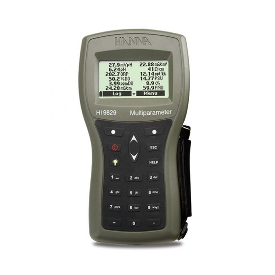
- Page 1 Instruction Manual HI 9829 Multiparameter Meter With available GPS, logging probe, turbidity and ion measurements...
- Page 3 Dear Customer, Thank you for choosing a HANNA instruments product. ® Please read this instruction manual carefully before using the instrument. It will provide you with the necessary information for correct use of the instrument, as well as it’s versatility.
-
Page 4: Table Of Contents
TABLE OF CONTENTS CHAPTER 1- INTRODUCTION 1.1 Preliminary Examination ..................6 1.2 Model Identification ....................6 1.3 General Description ....................6 1.4 Display and Keypad Description ................8 CHAPTER 2 - QUICK START 2.1 Sensor and Probe Installation ................9 2.2 Basic Operation .................... - Page 5 7.4 ORP Calibration ....................41 7.5 Dissolved Oxygen Calibration ................42 7.6 Conductivity Calibration ..................44 7.7 Turbidity Calibration .................... 48 7.8 Temperature Calibration ..................50 7.9 Atmospheric Pressure Calibration ................. 50 CHAPTER 8 - SYSTEM SETUP 8.1 Meter Setup ......................52 8.2 Probe Setup ......................
-
Page 6: Chapter 1- Introduction
D.O., EC+turbidity, temperature sensors with a long probe shield 1.3 GENERAL DESCRIPTION HI 9829 is a portable logging multiparameter system that monitors up to 14 different water quality parameters (7 measured, 7 calculated). The microprocessor-based intelligent multisensor probe allows measurement of... - Page 7 Google™ Maps. Clicking on visited locations using a mapping software displays the measurement information. All HI 9829 are equipped with Fast Tracker™ an invaluable tool for associating measurements with their locations. HANNA’s exclusive Fast Tracker™—T.I.S. (Tag ID System) uses iButton s that can be installed at any number of sampling sites.
-
Page 8: Display And Keypad Description
• USB interface for PC communication • Auto-ranging for EC, ISE and turbidity readings • Good Laboratory Practice feature, the last 5 calibrations are automatically stored • Field-replaceable sensors with color coded caps • Meter can be powered with either alkaline or rechargeable batteries •... -
Page 9: Chapter 2 - Quick Start
Chapter 2 - QUICK START Before you begin using the HI 9829 multiparameter system, either charge the included rechargeable C batteries for at least 6 hours or replace the rechargeable batteries with non-rechargeable alkaline batteries. 2.1 SENSOR AND PROBE INSTALLATION •... -
Page 10: Basic Operation
2.2 BASIC OPERATION The main operating modes for HI 9829 are measurement, logging and setup. The measurement screen can be configured to display a single measurement or up to 12 simultaneous measurements by using the numbers 1-7 on the keypad. -
Page 11: Help Function
2.3 HELP FUNCTION HI 9829 features context sensitive HELP, which provides useful information re- garding the displayed screen. Simply press the HELP key to access this function, then use the arrow keys to scroll through the message. -
Page 12: Chapter 3 - Specifications
Chapter 3 - SPECIFICATIONS 3.1 SYSTEM SPECIFICATIONS TEMPERATURE Range -5.00 to 55.00 °C; 23.00 to 131.00 °F; 268.15 to 328.15 K Resolution 0.01 °C; 0.01 °F; 0.01 K Accuracy ± 0.15 °C; ± 0.27 °F; ±0.15 K Calibration Automatic at 1 custom point pH/mV Range 0.00 to 14.00 pH;... - Page 13 CONDUCTIVITY Range 0 to 200 mS/cm (absolute EC up to 400 mS/cm) Resolution Manual 1 µS/cm; 0.001 mS/cm; 0.01 mS/cm; 0.1 mS/cm; 1 mS/cm Automati c 1 µS/cm from 0 to 9999 µS/cm 0.01 mS/cm from 10.00 to 99.99 mS/cm 0.1 mS/cm from 100.0 to 400.0 mS/cm Automatic (mS/cm) 0.001 mS/cm from 0.000 to 9.999 mS/cm...
- Page 14 SALINITY Range 0.00 to 70.00 PSU Resolution 0.01 PSU Accuracy ±2% of reading or ±0.01 PSU whichever is greater Calibration Based on conductivity calibration SEAWATER SIGMA Range 0.0 to 50.0 σ , σ , σ Resolution 0.1 σ , σ , σ...
- Page 15 Nitrate-Nitrogen Range 0.62 to 200.0 ppm Ni (as NO Resolution 0.01 ppm to 1 ppm 0.1 ppm to 200 ppm Accuracy ±5 % of reading or 2 ppm Calibration 1 or 2 point, 10 ppm and 100 ppm ATMOSPHERIC PRESSURE Range 450 to 850 mm Hg;...
- Page 16 METER BATTERY LIFE The power consumption of the HI 9829 multiparameter system is dependent on three things: 1. The measurement system configuration (probe type, sensor configuration) 2. The meter configuration (logging interval, GPS and backlight use) 3. The battery type (alkaline or rechargeable). Note: Alkaline batteries have two times the expected life.
-
Page 17: Probe Specifications
3.2 PROBE SPECIFICATIONS Non-logging Probe Logging Probe Sample Environment Fresh, brackish, seawater IP68 Waterproof protection Computer Interface USB PC (HI 76982910) Internal Battery Type 4 X 1.5V Size AA Alkaline Typical Battery Life See below Memory 140,000 measurements (single parameter logged) 35,000 measurements (all parameters logged) Operating Temperature... -
Page 18: Sensor Specifications
3.3 SENSOR SPECIFICATIONS HI 7609829-0 HI 7609829-1 HI 7609829-2 HI 7609829-3 Description pH/ORP Dissolved Oxygen Measure Type Primary Unit pH, mV (pH) pH, mV (pH/ORP) D.O. (% sat. & conc.) Measure Range 0.00 to 13.00 pH 0.00 to 13.00 pH 0.0 to 500.0 % 0.0 to 200.0 mS/cm ±600.0 mV... -
Page 19: Chapter 4 - Probe Installation
Chapter 4 - PROBE INSTALLATION HI 7609829 and HI 7629829 multisensor probes are used for the m e a - surements of pH, ORP, conductivity, turbidity, dissolved oxygen, chloride, nitrate- nitrogen, ammonium-nitrogen and temperature. Each probe can utilize 3 sen- sors. - Page 20 HI 7609829-10: Ammonium selective electrode (ISE) is a combination liquid membrane sensor used for the detec- tion of free ammonium-nitrogen in freshwater samples. The sensor utilizes a polymeric membrane made with ammo- nium ionophore in a PVC head and silver/silver chloride double junction gel filled reference electrode.
-
Page 21: Sensor Preparation/Activation
4.2 SENSOR PREPARATION / ACTIVATION 4.2.1 pH Preparation Remove the shipping cap from the pH sensor. If the shipping cap does not contain any liquid, pour HI 70300 into shipping cap, place it back on the sensor and soak for at least 1/2 hour before use. If HI 70300 is not available, pH 4.01 buffer may be substituted. - Page 22 Hold the sensor at the connec- tor and shake it down (like a mercury thermometer). Condition the sensor by soaking it in a small amount of HI 9829-10, 10 ppm NH -N standard for at least a 1/2 hour.
-
Page 23: Sensor Installation
4.3 SENSOR INSTALLATION The HI 76x9829 can support 3 different sensors: Connector 1: pH, pH/ORP or ISE (Ammonium, Chloride, Nitrate), Connector 2: D.O., Connector 3: EC or EC/Turbidity. To make installation easier, the sensors have color-coded caps and the sockets are identified with colored triangles. - Page 24 For a correct installation: • Grease the sensor O-ring with the lubricant found in the probe maintenance kit. DO NOT SUBSTITUTE other grease/lubricants as it may cause the O-ring to swell. • Insert the sensor into the correctly color coded opening while positioning the connector key toward the center of the probe.
-
Page 25: Chapter 5 - Initialization And Measurement
Note: Do not mix old and new alkaline batteries. 5.1.2 Charging Meter Batteries Two cables are available for charging the HI 9829 batteries: HI 710045 and HI 710046. AC power supply In order to charge the rechargeable batteries, use the HI 710045 cable and the 12 Vdc power adapter. - Page 26 It takes about 6 hours to completely charge fully discharged batteries. Note The meter log, GPS information, system setup and status can be viewed during battery charging. The battery charging status is indicated by a small animated battery icon found in the lower left corner. During charging the meter may feel quite warm.
-
Page 27: Meter Initialization
5.2 METER INITIALIZATION After connecting the desired sensors to the probe and connecting the probe to the meter (see previous chapter), turn the meter on by pressing ON/OFF. After the initialization has been completed, the meter displays the PROBE STA- TUS SCREEN. -
Page 28: Measurement Mode
5.3 MEASUREMENT MODE Measurement mode is one of the three main operating modes of HI 9829 (along with logging mode and setup mode). During measurement mode HI 9829 will simultaneously measure data for all enabled parameters. • Use the numbers on the keyboard to select the number of parameters that are shown on the screen at one time. -
Page 29: Setup Menu Structure
5.4 SETUP MENU STRUCTURE... -
Page 30: Chapter 6 - Parameter Setup Menu
Chapter 6 - PARAMETER SETUP MENU From the main menu, use the arrow keys to high- light “Parameter Setup” and then press <Select>. The following options will be displayed: 6.1 SELECT PARAMETERS Use the arrow keys to scroll through the menu. Press the right softkey to enable or disable a single parameter, or the left softkey to enable or disable all parameters. - Page 31 6.2.5 Resistivity Unit The user can select resistivity from one of the fol- lowing measurement units: Ω·cm, kΩ·cm or MΩ·cm. Resistivity is calculated from the conduc- tivity measurement. The default unit is MΩ·cm. 6.2.6 Seawater Sigma Unit This parameter is used for seawater analysis. It is calculated from the conductivity measurement and depends on water pressure, temperature and sa- linity.
-
Page 32: Parameter Coefficients
Auto ppt: the meter automatically chooses the range to optimize the measure- ment, readings will be in ppt only. 1 ppm, 0.001 ppt, 0.01 ppt, 0.1 ppt or 1 ppt: the meter will display the mea- surement with selected resolution. The default value is Auto. 6.2.11 GPS Format (optional) Global positioning coordinates have three standard formats: XX°XX’XX.X’’, XX°XX.XXX’... -
Page 33: Averaging
6.4 AVERAGING Averaging is a software filter to minimize sensor noise and provide more stable readings. Averaging is particularly useful to get a representative reading of the “average” value from flowing water. Averaging will affect all measurements (except Turbidity which can be set separately). This value should be kept low if you want a fast response. -
Page 34: Chapter 7 - Calibration Mode
Chapter 7 - CALIBRATION MODE HI 9829’s calibration routines are accessed by highlighting “Calibration” and pressing <Select> from the main menu. Calibration is the process that stan- dardizes the electrical or optical signals from the sensors to reagent standards of known value. -
Page 35: Quick Calibration
7.1 QUICK CALIBRATION The quick calibration method provides a quick single point calibration for pH, conductivity and dissolved oxygen sensors. HI 9828-25 calibration solution is used for both pH and conductivity. • Fill the calibration beaker 2/3 full with HI 9828-25 calibration solution. •... - Page 36 • Unscrew the calibration beaker and empty the solution. • Shake any remaining liquid off the probe and beaker. No droplets should remain on the D.O. sensor membrane. Note Do not attempt to dry wipe the D.O. sensor as damage to the mem brane may occur.
-
Page 37: Ph Calibration
7.2 pH CALIBRATION To optimize the pH measurement follow the general guidelines mentioned in the Chapter 7 introduction. From the “Calibration” menu select “Single param. calibration” and then “pH calibration”. The display shows two options: “Calibrate pH” and “Restore factory calib.”. If a new pH sensor has been installed use “Restore factory calib.”... - Page 38 • Press <Measure> to return to the measurement screen. Custom buffer calibration The HI 9829 permits a single custom buffer to be used for pH calibration. This can be used along with standard buffers as part of a 2 or 3 point calibration or as a single point.
- Page 39 7.2.3 pH Calibration Error Messages The HI 9829 displays a series of messages if an error has occurred during calibration. If the meter does not accept a pH calibration point, a short message is displayed to indicate the possible error source. The following screens are examples: These are the available messages: •...
-
Page 40: Ise Calibration
7.3 ISE CALIBRATION From the “Calibration” menu select “Single param. calibration” and then “ISE calibration”. The display shows two options: “Calibrate ISE” and “Restore factory calib”. When an ISE replaces a pH sensor or another ISE model, previous calibrations need to be cleared using the <Restore factory calib.>... -
Page 41: Orp Calibration
Position the sachet to ensure sensor membrane and ceramic junction are completely immersed in solution. A value close to 100 ppm and the message “Not ready...” will be displayed. • When the reading is stable, the countdown timer will count down until the display shows the “Ready”... -
Page 42: Dissolved Oxygen Calibration
7.4.1 Preparation Appendix D – ACCESSORIES lists Hanna solutions used for ORP calibrations. The calibration should be conducted at temperatures between 20-26°C. The sensor should be clean and oil free. 7.4.2 Procedure • From the “Calibration” menu select “Single param. calibration” and then “ORP calibration”. The display shows two options: “Custom ORP”... - Page 43 If the % D.O. saturation range is calibrated, the D.O. concentration range will also be calibrated, and vice versa. Dissolved oxygen concentration values are based on % D.O. saturation, temperature, salinity and atmospheric pressure. A standard solution or a reference D.O. meter may be used to compare readings during calibration.
-
Page 44: Conductivity Calibration
Note If the D.O. input is not within the acceptable range, the message “Invalid input” is displayed. Single point Custom % saturation calibration • For a calibration at another known value place sensor and temperature probe into the known solution and change the calibration value, press the <Cal. - Page 45 found in the bottom of the conductivity sensor. Clean using the small brush from the probe maintenance kit. Flush with water. A mild detergent may be used to remove oily coatings. Always flush with clean water after cleaning. Note For a correct conductivity calibration, the probe shield or the calibration beaker must be used.
- Page 46 • The main display shows the actual reading, while the secondary level displays the current temperature and the standard value. • To change the standard value, press <Cal. point> and the list of available standard values is displayed: 0 µS/cm, 84 µS/cm, 1413 µS/cm, 5.00 mS/cm, 12.88 mS/cm, 80.0 mS/cm and 111.8 mS/cm.
- Page 47 Salinity The measurement of salinity is based on the Practical Salinity Scale which uses the EC measurement. If the user has a standard with known PSU value it may be used to calibrate the conductivity sensor. • Select “Salinity” from the “Conductivity calibra- tion”...
-
Page 48: Turbidity Calibration
7.7 TURBIDITY CALIBRATION From the “Calibration” menu select “Single param. calibration” and then “Turbidity calibration”. The display shows two options: “Calibrate turbidity” and “Restore factory calib”. The Hanna turbidity sensor conforms to ISO 7027 standards which specifies the angle between the emitted and detected light and the light source wavelength. For best results perform a three point calibration at 0.0, 20.0, and 200.0 FNU. - Page 49 • Press <Confirm> to accept the calibration point and to continue with second standard. • Clean out the calibration beaker and refill with 20.0 FNU standard. • Immerse the sensor in the 20.0 FNU rinse beaker and then shake off excess solution.
-
Page 50: Temperature Calibration
“Temperature calib.” menu and then press <Select>. 7.9 ATMOSPHERIC PRESSURE CALIBRATION Place HI 9829 in a wind-free area and choose “Custom pressure” to perform a user calibration or “Restore factory calib”. Note “Custom pressure” procedure requires a reference barometer. - Page 51 • The stability counter will count down and the message “Ready” and “Confirm” will be displayed. Press <Confirm> to store the calibration point. • After confirmation, the following messages are displayed: “Storing” and “Cali- bration completed”. • Press <Measure> to return to the measurement screen. •...
-
Page 52: Chapter 8 - System Setup
Chapter 8 - SYSTEM SETUP From the main menu, select “System setup” and then “Meter setup” or “Probe setup”. 8.1 METER SETUP Note If the password protection is enabled, you will be required to enter the pass- word before any settings can be modi- fied. - Page 53 8.1.3 Auto Poweroff The Auto Poweroff function is used to save battery life. After the set time is elapsed, the meter will: 1. automatically switch off, if in normal measure- ment mode. Press On/Off to switch on again. 2. enter a sleeping mode, if the continuous log- ging mode is selected with a logging interval of at least 30 seconds.
- Page 54 8.1.8 Meter Password The Meter Password protects against unauthorized configuration changes and log data erasure. When implemented, many setting and functions cannot be modified or viewed. To enable the password proceed as follows: • Highlight “Meter Password” and press <Modify>. •...
-
Page 55: Probe Setup
8.1.11 Restore factory settings This function restores measurement settings to their original factory values. This includes measurement units, coefficients, other measurement configura- tions and all logged data. The factory calibration for the sensor channels is not affected. • Select the “Restore factory settings” and press <Select>. •... -
Page 56: Chapter 9 - Gps Menu (Optional)
Chapter 9 - GPS MENU (optional) HI 9829 model featuring GPS (Global Positioning System) is provided with a built-in 12 channel receiver and antenna to calculate meter position and track locations along with measurement data. The GPS has a position accuracy of 10 meters (30 ft). - Page 57 Press <Info> to view the GPS coordinates of the selected location. Press <Delete> to erase the selected location. Press <New> to add a new location. Coordinates for a new location can be entered manually or by using the current GPS coordinates. Clear all locations This option deletes all locations.
-
Page 58: Chapter 10 - Status
Chapter 10 - STATUS Useful information regarding the meter, probe (if connected) and GLP calibration data are avail- able for viewing by selecting “Status” from the main menu. 10.1 METER STATUS Select “Meter Status” to display information related to the battery, logging, internal temperature, password, Meter ID, serial number and firmware version. -
Page 59: Glp Data
10.3 GLP Data GLP (Good Laboratory Practice) is a set of functions that allows the user to store or recall data regarding the probe calibration. This feature also allows the user to associate readings with specific calibrations. To view GLP data select “GLP” from the “Status” menu. -
Page 60: Dissolved Oxygen
• From the “GLP” menu, select the “ISE” option. • Data regarding the last ISE calibration will be displayed: standards used, sensor type, time and date of the calibration. • Use the arrow keys to scroll through the stored data for the last 5 calibrations. •... - Page 61 Notes A “C” label near the calibration point indicates a custom point, while an “H” indicates a HANNA standard value. When the % D.O. range is calibrated, also the D.O. concentration range is calibrated, and vice versa. If no D.O. calibration has been performed or if calibration was cleared using the “Restore factory calib.”...
- Page 62 Notes If no turbidity calibration has been performed or if calibration was cleared using the “Restore factory calib.” option the offset and slope values are set to default, and the message ”Factory calibration” is dis- played. Press <ESC> to return to the previous screen. Temperature •...
-
Page 63: Chapter 11 - Logging Mode
Chapter 11 - LOGGING MODE The HI 9829 and HI 76x9829 system offers many logging options that can be combined based on user needs. The following figures describe the avail- able logging options. -
Page 65: Logging Menu Structure
11.1 LOGGING MENU STRUCTURE From measurement mode, press <Log> to access the log menu. 11.2 LOGGING ON METER • The data logged on the meter are organized by lots. Up to 44,000 complete records can be stored in up to 100 lots. Each lot can store log- on-demand records and/or continuous records with different parameter configurations. - Page 66 11.2.1 One Sample On Meter Use this option to log one set of enabled measurement parameters to the meter memory. • If there are no lots saved on the meter, press <New> to create a new lot. Use the keypad to enter the desired lot name and press <Accept>...
-
Page 67: Probe Log
11.2.2 Continuous meter log • Select “Start meter log” to log the currently en- abled parameters at the set logging interval on the meter. • To set the logging interval, highlight “Start meter log” and press <Options>. The log interval time can set from 1 second to 3 hours. -
Page 68: Log Recall
11.4 LOG RECALL • All logged data can be viewed using two log recall options. The data logged on probe can be accessed only if the probe is connected to the meter or to the HI 929829 PC application by using the “Probe log recall” option. The probe logs that have already been downloaded to the meter and the data logged on the meter can be viewed using the “Meter log recall”... - Page 69 • Press <Info> to see record information for the current sample (time & date, remark, location (only for model with GPS) and tag ID or serial number (if available).) • Press <Data> to return to the previous screen or <Jump> to select a different sample in the same lot.
-
Page 70: Log Notes
• After <View> is pressed, the meter displays all data related to the selected lot: number of samples, memory space used, time and date of the first and the last readings. • To see all the sample details press <Download>. When the download is completed, the log is now stored on the meter and can be accessed from the ‘’Meter log recall’’... -
Page 71: Delete All Remarks
• Press <Delete> to delete the selected remark from the meter. If the deleted remark is used in an existing lot, the information will be still available in the lot data. 11.5.2 Delete all remarks • Select “Delete all remarks” to delete all remarks. The display will show the message “Do you want to perform the current operation?”. - Page 72 • The tag information window will appear. Press <OK> to return to the previous screen or <Modify> to modify the tag ID. Note If the typed SN is not stored in memory, the warning message “SN not found” will be displayed. Search ID •...
-
Page 73: Chapter 12 - Pc Connection
• Once the lot has been downloaded, all the logged samples can be viewed. Windows is a registered Trademark of “Microsoft Co.” ® GOOGLE™ is a registered trademark of Google, Inc. HANNA instruments has no affiliation with Google™, Inc. ®... - Page 74 Meter to PC data a. Select parameter units b. Select Meter from toolbar c. Select Lot d. Select Map...
-
Page 75: Probe To Pc Connection
12.3 PROBE TO PC CONNECTION • Connect the HI 76982910 adapter to the probe and to a USB port on the PC. • Run the HI 929829 application software. • To access the probe, press the “Probe” button from the toolbar on the top of the screen. - Page 76 Probe Info Screen Lot Data Screen...
-
Page 77: Chapter 13 - Troubleshooting / Error Messages
Chapter 13 - TROUBLESHOOTING / ERROR MESSAGES HI 9829 displays error messages to aid in troubleshooting. Warnings are dis- played for most issues, while Errors are displayed for critical issues. See the calibration chapter for messages that can occur during calibration. Other messages are listed below. - Page 78 • ‘’GPS error’’ (only for models with GPS): the communication with the internal GPS unit can- not be established. Switch the meter off and on again, then retry. If the problem persists, remove the batteries, wait for 5 minutes and install them again.
- Page 79 • ‘’Warning x’’: Any other warning that appears at power-on is identified using a numeric code. Restart the meter. If the problem persists, contact the HANNA service center. Some meter/probe features can be accessed but with no guar- antee. • ‘’Errors x’’: Any critical errors that appear are identified using a numeric code, and the meter is automatically switched off.
-
Page 80: Appendixa - Probe Maintenance
APPENDIX A - PROBE MAINTENANCE The HI 7698292 probe maintenance kit includes HI 7042S (electrolyte solu- tion for D.O. sensor), spare membranes with o-rings for D.O. sensor, a small brush for cleaning EC , o-rings for sensor connectors and a syringe with grease to lubricate these o-rings. - Page 81 D.O. Sensor Maintenance For a top performance probe, it is recommended to replace the membrane every 2 months and the electrolyte monthly. Proceed as follows: • Unscrew the membrane by turning it counterclockwise. • Rinse a spare membrane with some electrolyte while shaking it gently.
- Page 82 • For long-term storage rinse the electrodes with water. Shake off the excess water and replace the storage cap to prevent evaporation of the reference electrolyte. • For chloride sensors (HI 7609829-11), if the sensor pellet appears tarnished, use a polishing strip to remove the oxidized surface. Cut off approximately a 1 inch piece of the strip.
-
Page 83: B - Probe Deployment
The Hanna HI 76X0929 has been designed for a variety of water quality measurements both in situ or in active deployments in urban or natural waters. The HI 9829 systems may be used for discrete spot sampling with a meter and the meter’s log on demand function, unattended with continuous monitoring and logging from the meter, or unattended using a logging probe. - Page 84 The probe is suitable for measurements in a flow cell. Pumping water to a flow- through monitoring station has obvious pros and cons. Typically a shelter is required to secure a pump, and flow chamber. A power requirement, shelter, pump maintenance and higher installation cost need to be considered. Freeze protection, security, and convenience of calibration and possibility of adding multiple measurement points and antifouling preconditioning systems are advantages to this type of installation.
-
Page 85: C - Ise Information
APPENDIX C - ISE INFORMATION This Appendix describes additional information about the ISE sensors used on the HI76x9829 Probe. HI 7609829-10: Ammonium selective electrode (ISE) is a combination liquid membrane sensor used for the detection of free ammonium-nitrogen in fresh- water samples. - Page 86 HI 76098290-10 Ammonium ion sensor linearity @25°C -100 0.01 1000 log ppm NH The calibration solutions and displayed measurements are as ppm Ammonium- nitrogen. Due to the space restriction of the display the unit of measurement will be displayed as “ppmAm”. The ammonium sensor will last longer in colder clean waters than in severely contaminated water or warmer waters.
- Page 87 HI 7609829-11: Chloride ion selective electrode is a combination solid state sensor used for the detection of free chloride ions in freshwater samples. The sensor utilizes a silver chloride pellet housed in a PEI head and a silver/silver chloride double junction gel filled reference electrode. The outer body of the sensor is the thermoplastic PEI.
- Page 88 The calibration solutions and displayed measurements are as ppm Chloride ions. Due to the space restriction of the display the unit of measurement will be displayed as “ppmCl” (without charge). The chloride sensor will last longer in colder clean waters than in severely contaminated water or warmer waters.
- Page 89 HI 7609829-12: Nitrate ion selective electrode is a combination liquid mem- brane sensor used for the detection of nitrate nitrogen in freshwater samples. The sensor utilizes a polymeric membrane made with nitrate ionophore in a PVC head and a silver/silver chloride double junction gel filled reference electrode. The outer body of the sensor is the thermoplastic PEI.
- Page 90 The calibration solutions and displayed measurements are as ppm Nitrate- nitrogen. Due to the space restriction of the display the unit of measurement will be displayed as “ppmNi”. The nitrate sensor will last longer in colder clean waters than in severely contaminated water or warmer waters.
-
Page 91: D - Accessories
Meter only, manual, charging cable adapter for 115VAC HI 9829-01 Meter only, manual, charging cable adapter for 230VAC HI 9829-02 HI 9829 with GPS, manual, charging cable adapter for HI 98290-01 115VAC HI 9829 with GPS, manual, charging cable adapter... - Page 92 115VAC Same as HI 98295-01, for 230VAC HI 98295-02 HI 98290 with GPS and HI 9829 and HI 7639829/4 logging HI 98296-01 probe for pH/pH+ORP/ISE, D.O., EC/EC+turbidity, temperature with HI 7698296 long protective shield and 4 meter (13.1’) cable, probe maintenance kit, manual, charging...
- Page 93 HI 98290 with GPS and HI 7629829/10 logging probe for HI 98297-01 pH/pH+ORP/ISE, D.O., EC, temperature with HI 7698295 short protective shield and 10 meter (33’) cable, probe maintenance kit, manual, charging cable adapter, for 115VAC Same as HI 98297-01, for 230VAC HI 98297-02 HI98290 with GPS and HI 7639829/10 logging probe for HI 98298-01...
- Page 94 HI 710012 230 VAC/12 VDC adapter, South African plug HI 710013 230 VAC/12 VDC adapter, Australian plug HI 710014 Hard carrying case for HI 9829 HI 710140 QUICK CALIBRATION SOLUTIONS Quick calibration solution, 500 mL HI 9828-25 Quick calibration solution, 1 gal.
- Page 95 111800 µS/cm calibration solution, 500 mL HI 7035L 5000 µS/cm calibration solution, 500 mL HI 7039L TURBIDITY SOLUTIONS 0 FNU turbidity calibration solution, 100 mL HI 9829-16 20 FNU turbidity calibration solution, 100 mL HI 9829-17 200 FNU turbidity calibration solution, 100 mL HI 9829-18...
- Page 96 ISE SOLUTIONS 10 ppm ammonium (as N) standard for HI 7609829-10, HI 9829-10 25 x 25 mL sachet 100 ppm ammonium (as N) standard for HI 7609829-10, HI 9829-11 25 x 25 mL sachet 10 ppm chloride standard for HI 7609829-11,...
-
Page 97: E - Warranty
If the repair is not covered by the warranty, you will be notified of the charges incurred. If the instrument is to be returned to HANNA instruments , first obtain a ® Returned Goods Authorization number from the Customer Service department and then send it with shipping costs prepaid.
Need help?
Do you have a question about the HI 9829 and is the answer not in the manual?
Questions and answers