Motorola DS6878 Product Reference Manual
Hide thumbs
Also See for DS6878:
- Product reference manual (629 pages) ,
- Reference manual (510 pages) ,
- Quick start manual (2 pages)
Table of Contents
Advertisement
Quick Links
Advertisement
Table of Contents
Troubleshooting

Related Manuals for Motorola DS6878


Summary of Contents for Motorola DS6878
- Page 1 DS6878 PRODUCT REFERENCE GUIDE...
-
Page 3: Product Reference Guide
DS6878 PRODUCT REFERENCE GUIDE 72E-131700-05 Revision A August 2014... - Page 4 Third Party Software will then be governed by the separate Commercial Third Party License. The Publicly Available Software that may be included on this media, or in the Motorola Product, is listed below. The use of the listed Publicly Available Software is subject to the licenses, terms and conditions of the agreement in force between the purchaser of the Motorola Product and Motorola, Inc., as well as, the terms and conditions of the license of each Publicly...
-
Page 5: Warranty
OTHERWISE) ARISING IN ANY WAY OUT OF THE USE OF THIS SOFTWARE, EVEN IF ADVISED OF THE POSSIBILITY OF SUCH DAMAGE. Motorola Solutions, Inc. One Motorola Plaza Holtsville, New York 11742-1300 http://www.motorolasolutions.com Warranty For the complete Motorola hardware product warranty statement, go to: http://www.motorolasolutions.com/warranty. -
Page 6: Revision History
DS6878 Product Reference Guide Revision History Changes to the original manual are listed below: Change Date Description -01 Rev A 4/2010 Initial release. -02 Rev A 3/2011 Add: CR0078-P cradle, FIPS configurations, Imaging Preferences chapter, hands-free scanning instructions, Page Button, Chapter 7: SNAPI Parameters,... - Page 7 Change Date Description -04 Rev A 12/2013 Update URLs. Remove cradle Wall Mount Bracket Template. Replaced parameter SSI values with attribute numbers. Add Apple iOS HID Feature and Android HID Feature. Add Secure Simple Pairing IO Capability. Add Connecting an iOS or Android Product With the Digital Scanner. Add Decode Pager Motor and Decode Pager Motor Duration.
- Page 8 DS6878 Product Reference Guide...
-
Page 9: Table Of Contents
TABLE OF CONTENTS Warranty ............................iii Revision History ..........................iv About This Guide Introduction ............................. xvii Configurations..........................xvii Chapter Descriptions ........................xviii Notational Conventions........................xix Related Documents ........................xx Service Information ......................... xx Chapter 1: Getting Started Introduction ............................ 1-1 Interfaces ............................ - Page 10 DS6878 Product Reference Guide Shutting Off the Digital Scanner Battery ..................1-15 Reconditioning the Digital Scanner Battery ................... 1-16 Battery Reconditioning LED Definitions ................... 1-16 Radio Communications ........................1-17 Configuring the Digital Scanner ..................... 1-17 Accessories ........................... 1-17 Lanyard ............................ 1-17 Chapter 2: Scanning Introduction ............................
- Page 11 Table of Contents HID Keyboard Keystroke Delay ....................4-13 HID CAPS Lock Override ......................4-13 HID Ignore Unknown Characters ..................... 4-14 Emulate Keypad ........................4-14 HID Keyboard FN1 Substitution ....................4-15 HID Function Key Mapping ...................... 4-15 Simulated Caps Lock ....................... 4-16 Convert Case ...........................
- Page 12 DS6878 Product Reference Guide Digital Scanner Activity Modes ....................5-22 Time Delay to Presentation Idle Mode ..................5-23 Time Delay to Presentation Sleep Mode ................. 5-25 Time Delay to Presentation Sleep Mode (continued) .............. 5-26 Timeout to Low Power Mode from Auto Aim ................5-27 Picklist Mode ..........................
- Page 13 Table of Contents JPEG Image Options ....................... 6-10 JPEG Target File Size ......................6-11 JPEG Quality and Size Value ....................6-11 Image Enhancement ........................ 6-12 Image File Format Selector ...................... 6-13 Image Rotation ......................... 6-14 Bits Per Pixel ..........................6-15 Signature Capture ........................
- Page 14 DS6878 Product Reference Guide Check Receive Errors ......................8-10 Hardware Handshaking ......................8-10 Software Handshaking ......................8-12 Host Serial Response Time-out ....................8-14 RTS Line State ......................... 8-15 Beep on <BEL> ........................8-15 Intercharacter Delay ......................... 8-16 Nixdorf Beep/LED Options ....................... 8-17 Ignore Unknown Characters ....................
- Page 15 Table of Contents Leading Margin (Quiet Zone) ....................11-4 Polarity ............................. 11-5 Ignore Unknown Characters ....................11-5 Convert All Bar Codes to Code 39 ................... 11-6 Convert Code 39 to Full ASCII ....................11-6 Chapter 12: Scanner Emulation Interface Connecting Using Scanner Emulation ................... 12-2 Scanner Emulation Parameter Defaults ..................
- Page 16 DS6878 Product Reference Guide OCR Check Digit Multiplier ...................... 14-26 OCR Check Digit Validation ..................... 14-27 Inverse OCR ..........................14-32 Chapter 15: Symbologies Introduction ............................ 15-1 Scanning Sequence Examples ...................... 15-1 Errors While Scanning ........................15-2 Symbology Parameter Defaults ..................... 15-2 UPC/EAN ............................
- Page 17 Table of Contents xiii Code 39 Buffering - Scan & Store .................... 15-32 Code 93 ............................15-35 Enable/Disable Code 93 ......................15-35 Set Lengths for Code 93 ......................15-35 Code 11 ............................15-37 Code 11 ........................... 15-37 Set Lengths for Code 11 ......................15-37 Code 11 Check Digit Verification .....................
- Page 18 Flush Macro Buffer ........................15-84 Abort Macro PDF Entry ......................15-84 Chapter 16: Advanced Data Formatting Introduction ............................ 16-1 Chapter 17: Driver’s License Set Up (DS6878-DL) Introduction ............................ 17-1 DL Parsing Parameter Defaults ..................... 17-2 Driver’s License Parsing ........................ 17-3 Parsing Driver’s License Data Fields (Embedded Driver's License Parsing) ........
- Page 19 Table of Contents User Preferences ........................... 17-17 Set Default Parameter ......................17-17 Output Gender as M or F ......................17-17 Date Format ..........................17-18 Send Keystroke (Control Characters and Keyboard Characters) ..........17-20 Parsing Rule Example ........................17-39 Embedded Driver's License Parsing ADF Example ..............17-43 Appendix A: Standard Default Parameters Appendix B: Programming Reference Symbol Code Identifiers .........................
- Page 20 DS6878 Product Reference Guide Start / Stop Patterns ........................G-2 Dimensions ............................ G-3 Data Format ........................... G-3 Additional Capabilities ........................G-4 Signature Boxes ..........................G-4 Appendix H: Non-Parameter Attributes Introduction ............................ H-1 Attributes ............................H-1 Model Number ......................... H-1 Serial Number .......................... H-1 Date of Manufacture ........................
-
Page 21: About This Guide
ABOUT THIS GUIDE Introduction The DS6878 Product Reference Guide provides general instructions for setting up, operating, maintaining, and troubleshooting the DS6878 digital scanner and cradles. Configurations This guide includes the following configurations: • DS6878-SR20001WR - DS6878 digital scanner, standard range, cash register white •... -
Page 22: Chapter Descriptions
This chapter also contains the bar codes for advanced data formatting. • Chapter 17, Driver’s License Set Up (DS6878-DL) describes how the DS6878-DL digital scanner can parse out information from the standard US driver’s licenses and certain other American Association of Motor Vehicle Administrators (AAMVA) compliant ID cards. -
Page 23: Notational Conventions
About This Guide • Appendix C, Sample Bar Codes includes sample bar codes. • Appendix D, Numeric Bar Codes includes the numeric bar codes to scan for parameters requiring specific numeric values. • Appendix E, Alphanumeric Bar Codes includes the bar codes representing the alphanumeric keyboard, used when setting ADF rules. -
Page 24: Related Documents
Software type and version number. Motorola responds to calls by e-mail, telephone or fax within the time limits set forth in service agreements. If your problem cannot be solved by Motorola Solutions support, you may need to return your equipment for servicing and will be given specific directions. -
Page 25: Chapter 1 Getting Started
CHAPTER 1 GETTING STARTED Introduction The DS6878 combines superior 1D and 2D omnidirectional bar code scanning performance and advanced ergonomics in a light-weight design. The digital scanner ensures comfort and ease of use for extended periods of time. DS6878 Digital Scanner... -
Page 26: Interfaces
Unpacking the Digital Scanner and Cradle Remove the digital scanner and cradle from their respective packing and inspect for damage. If the digital scanner or cradle was damaged in transit, contact Motorola Solutions Support. See page xx for contact information. -
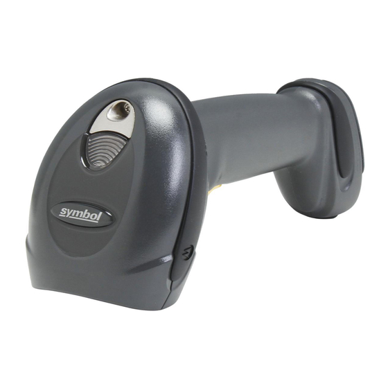
Page 27: Parts
Getting Started 1 - 3 Parts Scanner Scan Beeper Window Battery Door Latch Trigger Metal Charging Contacts Parts of the Digital Scanner Figure 1-2... -
Page 28: Cr0078-S/Cr0008-S Series Cradle
1 - 4 DS6878 Product Reference Guide CR0078-S/CR0008-S Series Cradle Pairing Bar Code Convertible Mount Hook Charging LED Latch Latch Charging/ Communications Contacts CR0078-S/CR0008-S Series Cradle Front View Figure 1-3... - Page 29 Getting Started 1 - 5 Mounting Hole Rubber Foot Rubber Foot Host Cable Hook Power Cable Hook Power Port Host Port Host Cable Groove Power Cable Groove Desk/Wall Mount Converter Knob Rubber Foot Rubber Foot Mounting Hole CR0078-S/CR0008-S Series Cradle Back View Figure 1-4...
-
Page 30: Cr0078-P Series Cradle
1 - 6 DS6878 Product Reference Guide CR0078-P Series Cradle Latch Charging/ Communication Contacts Page Button CR0078-P Cradle Front View Figure 1-5 Power Cable Host Cable Groove Groove Rubber Foot Rubber Foot Host Cable Groove Power Cable Groove Cable Support Hook... -
Page 31: Digital Scanner Cradle
Getting Started 1 - 7 Digital Scanner Cradle The digital scanner cradles CR0078-S and CR0078-P serve as a stand, charger, and host interface for the digital scanner. The cradle sits on a desktop. The CR0078-S cradle can also be mounted on a vertical surface (such as a wall). -
Page 32: Connecting The Cr0078-S/Cr0008-S Series Cradle
1 - 8 DS6878 Product Reference Guide Connecting the CR0078-S/CR0008-S Series Cradle Connect the interface cable and power supply (if necessary) in the following order to ensure proper operation of the digital scanner and cradle: NOTE The CR0078-S cradle has the ability to be powered by the USB port instead of an external power supply. -
Page 33: Supplying Power To The Cr0078-S/Cr0008-S Cradle
Getting Started 1 - 9 Supplying Power to the CR0078-S/CR0008-S Cradle The CR0078-S/CR0008-S cradle receives power from one of two sources: • An external power supply. • When connected to the host through a host cable that supplies power (CR0078-S only). The cradle detects whether the host or the external supply is supplying power. -
Page 34: Supplying Power To The Cr0078-P Cradle
1 - 10 DS6878 Product Reference Guide If necessary (for non-autodetected interfaces), scan the appropriate host bar code (refer to the CR0078-S/CR0008-S Cradle Quick Reference Guide for more information). Power Port Connect to appropriate host Power Alternate Host Groove Alternate Power Groove... -
Page 35: Replacing The Digital Scanner Battery
Getting Started 1 - 11 Replacing the Digital Scanner Battery The battery is installed in the cordless digital scanner by the factory and resides in a chamber in the digital scanner handle. To replace the battery: Insert a Phillips screwdriver in the screw at the base of the digital scanner, then turn the screw counterclockwise to release the latch. -
Page 36: Inserting The Digital Scanner In The Cradle
1 - 12 DS6878 Product Reference Guide Inserting the Digital Scanner in the Cradle Insert the digital scanner in the cradle so that the metal contacts on the bottom of the digital scanner handle touch the contacts on the cradle. Push the handle lightly to ensure a proper connection, engaging the contacts in the cradle and digital scanner. -
Page 37: Inserting/Removing Digital Scanner In The Cr0078-P Cradle
Getting Started 1 - 13 Ensure the desk/wall mount converter knob is in the position shown in Figure 1-11. Desk/Wall Mount Converter Knob Vertical Mount - Inserting the Digital Scanner in the Cradle Figure 1-11 Inserting/Removing Digital Scanner in the CR0078-P Cradle To insert the scanner in the cradle: Insert the scanner by placing the bottom of the scanner, at a slight forward angle, into the CR0078-P cradle. - Page 38 1 - 14 DS6878 Product Reference Guide To remove the scanner from the cradle: Remove the scanner by pushing the scanner slightly forward and up out of the CR0078-P cradle. Click Removing the Digital Scanner in the Cradle Figure 1-13...
-
Page 39: Charging The Digital Scanner Battery
Getting Started 1 - 15 Charging the Digital Scanner Battery Fully charge the digital scanner battery before using the digital scanner for the first time. To charge the digital scanner battery, place the digital scanner in the cradle, ensuring that the metal contacts on the bottom of the digital scanner touch the contacts on the cradle. -
Page 40: Reconditioning The Digital Scanner Battery
1 - 16 DS6878 Product Reference Guide Reconditioning the Digital Scanner Battery To maintain optimal performance of the digital scanner NiMH battery, perform a battery recondition approximately once a year. To begin the battery recondition cycle: Scan Battery Recondition below. -
Page 41: Radio Communications
Getting Started 1 - 17 Radio Communications The digital scanner can communicate with remote devices via Bluetooth Technology Profile Support, or by pairing with a cradle. For radio communication parameters, detailed information about operational modes, Bluetooth Technology Profile Support and pairing, see Chapter 4, Radio Communications. - Page 42 1 - 18 DS6878 Product Reference Guide To attach the lanyard: Open the battery door latch as described in Replacing the Digital Scanner Battery on page 1-11. Do not remove the battery. Hook the loop of the lanyard around the screw container inside the battery door latch, between the loop guides.
-
Page 43: Chapter 2 Scanning
CHAPTER 2 SCANNING Introduction This chapter provides beeper and LED definitions, scanning techniques, general instructions and tips about scanning, and decode ranges. Beeper Definitions The digital scanner issues different beep sequences and patterns to indicate status. Table 2-1 defines beep sequences that occur during both normal scanning and while programming the digital scanner. -
Page 44: Cancel
2 - 2 DS6878 Product Reference Guide Standard Beeper Definitions (Continued) Table 2-1 Beeper Sequence Indication Low beep Digital scanner detects power when inserted into a cradle. Note: This feature is enabled by default and can be disabled (see Beep on Insertion on page 5-10). -
Page 45: Led Definitions
Scanning 2 - 3 Standard Beeper Definitions (Continued) Table 2-1 Beeper Sequence Indication Host Specific USB only Four high beeps Digital scanner has not completed initialization. Wait several seconds and scan again. Digital scanner gives a power-up beep after Communication with the bus must be established before the digital scanning a USB Device Type. - Page 46 If the solid red LED condition persists, there may be a problem with the battery or the scanner, in which case discontinue use of the scanner and contact Motorola Solutions support. Scanner LED Definitions with CR0078-P Cradle...
-
Page 47: Scanning
Scanning 2 - 5 Scanning To program the digital scanner, see the appropriate host chapter, Chapter 4, Radio Communications Chapter 15, Symbologies. (In addition to the parameters included in these chapters, user preferences and miscellaneous digital scanner options are also available in this guide.) Hand-held Scanning To scan: Ensure all connections are secure (see appropriate host chapter). -
Page 48: Hands-Free Scanning
2 - 6 DS6878 Product Reference Guide Hands-free Scanning The digital scanner is in hands-free (presentation) mode when it sits in the CR0078-P cradle. In this mode the digital scanner operates in continuous (constant-on) mode, where it automatically decodes a bar code presented in the field of view. - Page 49 Scanning 2 - 7 To scan a bar code, center the symbol in any orientation within the aiming pattern. Ensure the entire symbol is within the rectangular area formed by the cross pattern. 2D bar code 1D bar code Symbol Aiming Pattern Scanning Orientation with Imager Aiming Pattern Figure 2-4...
-
Page 50: Decode Ranges
2 - 8 DS6878 Product Reference Guide Decode Ranges DS6878-SR / DS6878-HC / DS6878-DL Decode Ranges Table 2-6 Typical Working Ranges Symbol Density Bar Code Type Near 5 mil Code 39 13 mil 100% UPC 14.2 5 mil 6.6 mil... -
Page 51: Chapter 3: Maintenance, Troubleshooting & Technical Specifications
Do not spray water or other cleaning liquids directly into the window. The DS6878-HC design allows safe cleansing of the product plastics with a variety of cleaning products and disinfectants. If required, wipe the digital scanner with the following list of approved cleansers: •... -
Page 52: Digital Scanner Cradle
Avoid using cleansers directly on the digital scanner battery door, contacts and cradle contacts. Use a CAUTION cotton swab moistened with alcohol to gently clean contacts. Known Harmful Ingredients The following chemicals are known to damage the plastics on Motorola scanners/cradles and should not come in contact with the device: • Ammonia solutions •... -
Page 53: Monthly 'Deep Cleaning' Maintenance
3 - 3 Monthly 'Deep Cleaning' Maintenance Keep your Motorola scanner and cradle in good working order with a regular comprehensive cleaning routine to remove the natural build-up of dirt that occurs with everyday use on connectors and the scanner exit window as well as, the main surfaces of the device. -
Page 54: Battery Information
Replace the battery when a significant loss of run time is detected. Batteries must be charged within the 32° F to 104° F (0° C to 40°C) temperature range. The standard warranty period for all Motorola Solutions batteries is 30 days, regardless if the battery was purchased separately or included as part of the digital scanner. - Page 55 Maintenance, Troubleshooting & Technical Specifications 3 - 5 Troubleshooting (Continued) Table 3-1 Problem Possible Causes Possible Solutions Digital Scanner emits a Out of ADF parameter storage Erase all rules and re-program with low/high/low/high beep sequence space. shorter rules. while it is being programmed. Digital Scanner emits long low/long Input error, incorrect bar code or Scan the correct numeric bar codes...
- Page 56 3 - 6 DS6878 Product Reference Guide Troubleshooting (Continued) Table 3-1 Problem Possible Causes Possible Solutions Digital Scanner emits four long low A transmission error was This occurs if a unit is not properly beeps. detected in a scanned symbol.
- Page 57 Maintenance, Troubleshooting & Technical Specifications 3 - 7 Troubleshooting (Continued) Table 3-1 Problem Possible Causes Possible Solutions Cradle has lost connection to In this exact order: disconnect power host. supply; disconnect host cable; wait three seconds; reconnect host cable; reconnect power supply; reestablish pairing.
- Page 58 Interface/power cables are loose. Check battery and charging contacts; ensure power and cable connections to cradle are secure. NOTE If after performing these checks the symbol still does not scan, contact the distributor or contact Motorola Solutions Support. See page xx...
-
Page 59: Technical Specifications
Maintenance, Troubleshooting & Technical Specifications 3 - 9 Technical Specifications Technical Specifications - DS6878 Digital Scanner Table 3-2 Item Description Physical Characteristics Dimensions 7.3 in. H x 3.85 in. L x 2.7 in. W (18.5 cm H x 9.7 cm L x 6.9 cm W) Weight (with battery) Approximately 8.4 oz. - Page 60 3 - 10 DS6878 Product Reference Guide Technical Specifications - DS6878 Digital Scanner (Continued) Table 3-2 Item Description Ambient Light Immunity Incandescent - 150 ft. candles (1,600 Lux) Sunlight - 8,000 ft. candles (86,000 Lux) Fluorescent - 150 ft. candles (1,600 Lux) Mercury Vapor - 150 ft.
- Page 61 Maintenance, Troubleshooting & Technical Specifications 3 - 11 Technical Specifications - CR0078-S/CR0008 Cradle (Continued) Table 3-3 Item Description Accessories Mounting Options Desktop, mount on a wall, computer work station or medical cart. Power Supplies Power supplies are available for applications that do not supply power over host cable.
-
Page 62: Cradle Signal Descriptions
3 - 12 DS6878 Product Reference Guide Cradle Signal Descriptions The signal descriptions in Table 3-5 apply to the connector on the digital scanner and are for reference only. Cradle Signal Pin-outs Table 3-5 Keyboard Synapse RS-232 Wand Wedge Reserved... -
Page 63: Chapter 4 Radio Communications
CHAPTER 4 RADIO COMMUNICATIONS Introduction This chapter provides information about the modes of operation and features available for wireless communication between digital scanners, cradles and hosts. The chapter also includes the parameters necessary to configure the digital scanner. The digital scanner ships with the settings shown in the Radio Communication Default Parameters on page 4-2 (also see Appendix A, Standard Default Parameters... -
Page 64: Radio Communications Parameter Defaults
4 - 2 DS6878 Product Reference Guide Radio Communications Parameter Defaults Table 4-1 lists the defaults for radio communication parameters. If you wish to change any option, scan the appropriate bar code(s) provided in the Radio Communications Parameters section beginning on page 4-4. -
Page 65: Wireless Beeper Definitions
Radio Communications 4 - 3 Radio Communication Default Parameters Table 4-1 Page Parameter Default Number Variable Pin Code Static 4-30 Encryption Disable 4-31 Secure Simple Pairing IO Capability No Input/No Output 4-32 (SPP Server and SPP Master Host Mode Only) Wireless Beeper Definitions When the digital scanner scans the pairing bar code it issues various beep sequences indicating successful or unsuccessful operations. -
Page 66: Radio Communications Host Types
4 - 4 DS6878 Product Reference Guide Radio Communications Host Types To set up the digital scanner for communication with a cradle, or to use standard Bluetooth profiles, scan the appropriate host type bar code below. • Cradle Host (default) - Select this host type for digital scanner(s) to cradle operation. The digital scanner must then be paired to the cradle and the cradle communicates directly to the host via the host interface cable connection. - Page 67 Radio Communications 4 - 5 Radio Communications Host Types (continued) *Cradle Host Serial Port Profile (Master) Serial Port Profile (Slave) Bluetooth Keyboard Emulation (HID Slave)
-
Page 68: Bluetooth Technology Profile Support
4 - 6 DS6878 Product Reference Guide Bluetooth Technology Profile Support With Bluetooth Technology Profile Support, the cradle is not required for wireless communication. The digital scanner communicates directly to the host using Bluetooth technology. The digital scanner supports the standard Bluetooth Serial Port Profile (SPP) and HID Profiles which enable the digital scanner to communicate with other Bluetooth devices that support these profiles. -
Page 69: Bluetooth Friendly Name
Select General Discoverable Mode when initiating connection from a PC. • Select Limited Discoverable Mode when initiating connection from a mobile device (e.g., Motorola Q), and the device does not appear in General Discoverable Mode. Note that it can take longer to discover the device in this mode. -
Page 70: Wi-Fi Friendly Mode
4 - 8 DS6878 Product Reference Guide Wi-Fi Friendly Mode Scanners configured for Wi-Fi friendly mode behave as follows: • The scanner remains in sniff mode, and exits sniff mode only during firmware update. • If any Wi-Fi channel is excluded from the hopping sequence, AFH turns off. - Page 71 Radio Communications 4 - 9 Wi-Fi Friendly Channel Exclusion (continued) Use All Channels (Standard AFH) Exclude Wi-Fi Channel 1 Exclude Wi-Fi Channel 6 Exclude Wi-Fi Channel 11 Exclude Wi-Fi Channels 1, 6, and 11 Exclude Wi-Fi Channels 1 and 6 Exclude Wi-Fi Channels 1 and 11 Exclude Wi-Fi Channels 6 and 11...
-
Page 72: Hid Host Parameters
4 - 10 DS6878 Product Reference Guide HID Host Parameters The digital scanner supports keyboard emulation over the Bluetooth HID profile. In this mode the digital scanner can interact with Bluetooth enabled hosts supporting the HID profile as a Bluetooth keyboard. -
Page 73: Hid Country Keyboard Types (Country Codes)
Radio Communications 4 - 11 HID Country Keyboard Types (Country Codes) Scan the bar code corresponding to the keyboard type. North American Standard Keyboards French Windows French Canadian Windows 98 French International German Windows... - Page 74 4 - 12 DS6878 Product Reference Guide HID Country Keyboard Types (continued) Spanish Windows Italian Windows Swedish Windows UK English Windows Japanese Windows French Canadian Windows 2000/XP Portuguese/Brazilian Windows...
-
Page 75: Hid Keyboard Keystroke Delay
Radio Communications 4 - 13 HID Keyboard Keystroke Delay This parameter sets the delay, in milliseconds, between emulated keystrokes. Scan a bar code below to increase the delay when the HID host requires a slower transmission of data. No Delay (0 msec) Medium Delay (20 msec) Long Delay (40 msec) HID CAPS Lock Override... -
Page 76: Hid Ignore Unknown Characters
4 - 14 DS6878 Product Reference Guide HID Ignore Unknown Characters Unknown characters are characters the host does not recognize. When Send Bar Codes With Unknown Characters is scanned, all bar code data is sent except for unknown characters, and no error beeps sound. -
Page 77: Hid Keyboard Fn1 Substitution
Radio Communications 4 - 15 HID Keyboard FN1 Substitution When enabled, this parameter allows replacement of any FN1 character in an EAN128 bar code with a Key Category and value chosen by the user. See FN1 Substitution Values on page 5-50 to set the Key Category and Key Value. -
Page 78: Simulated Caps Lock
4 - 16 DS6878 Product Reference Guide Simulated Caps Lock When enabled, the digital scanner inverts upper and lower case characters on the digital scanner bar code as if the Caps Lock state is enabled on the keyboard. This inversion is done regardless of the current state of the keyboard Caps Lock state. -
Page 79: Auto-Reconnect Feature
Radio Communications 4 - 17 Auto-reconnect Feature When in SPP Master or Cradle Host mode, the digital scanner automatically tries to reconnect to a remote device when a disconnection occurs that is due to the radio losing communication. This can happen if the digital scanner goes out of range with the remote device, or if the remote device powers down. -
Page 80: Reconnect Attempt Beep Feedback
4 - 18 DS6878 Product Reference Guide Reconnect Attempt Beep Feedback When a digital scanner disconnects as it goes out of range, it immediately attempts to reconnect. While the digital scanner attempts to reconnect, the green LED continues to blink. If the auto-reconnect process fails, the digital scanner emits a page timeout beep (long low/long high) and stops blinking the LED. -
Page 81: Reconnect Attempt Interval
Radio Communications 4 - 19 Reconnect Attempt Interval When a digital scanner disconnects as it goes out of range, it immediately attempts to reconnect for the default time interval of 30 seconds. This time interval can be changed to one of the following options: •... -
Page 82: Auto-Reconnect In Bluetooth Keyboard Emulation (Hid Slave) Mode
4 - 20 DS6878 Product Reference Guide Auto-reconnect in Bluetooth Keyboard Emulation (HID Slave) Mode In Bluetooth Keyboard Emulation (HID Slave) mode, select a re-connect option for when the digital scanner loses its connection with a remote device: • Auto-reconnect on Bar Code Data: The digital scanner auto-reconnects when you scan a bar code. -
Page 83: Digital Scanner(S) To Cradle Support
Radio Communications 4 - 21 Digital Scanner(s) To Cradle Support Modes of Operation The charging cradle with radio supports two radio communication modes of operation, allowing the digital scanner to communicate wirelessly: • Point-to-Point • Multipoint-to-Point. Point-to-Point Communication In Point-to-Point communication mode, the cradle allows one digital scanner to connect to it at a time. In this mode, the digital scanner is paired to the cradle either by insertion into the cradle (if pairing on contacts is enabled, page... -
Page 84: Parameter Broadcast (Cradle Host Only)
4 - 22 DS6878 Product Reference Guide Parameter Broadcast (Cradle Host Only) When in multipoint-to-point mode, enable Parameter Broadcast to broadcast all parameter bar codes scanned to all other digital scanners in the piconet. If disabled, parameter bar codes are processed by the individual digital scanner only, and the digital scanner ignores parameters broadcast from other digital scanners or from the cradle. - Page 85 Radio Communications 4 - 23 Pairing Modes When operating with the cradle, two modes of pairing are supported: • Locked Pairing Mode - When a cradle is paired (connected) to the digital scanner (or up to three digital scanners for the CR0078-S and up to seven digital scanners for the CR0078-P in Multipoint-to-Point mode), any attempt to connect a different digital scanner, by either scanning the PAIR bar code on the cradle or by inserting it into the cradle with the pairing on contacts feature enabled ( page...
- Page 86 Unpair the digital scanner from the cradle or PC/host to make the cradle available for pairing with another digital scanner. Scan the bar code below to disconnect the digital scanner from its cradle/PC host. An unpairing bar code is also included in the DS6878 Quick Reference Guide. Unpairing...
-
Page 87: Pairing Bar Code Format
Radio Communications 4 - 25 Pairing Bar Code Format When the digital scanner is configured as an SPP Master, you must create a pairing bar code for the remote Bluetooth device to which the digital scanner can connect. The Bluetooth address of the remote device must be known. -
Page 88: Connection Maintenance Interval
4 - 26 DS6878 Product Reference Guide Connection Maintenance Interval NOTE The Connection Maintenance Interval only applies in locked pairing mode (see page 4-23). When a digital scanner disconnects from a cradle due to a Link Supervision Timeout, the digital scanner immediately attempts to reconnect to the cradle for 30 seconds. - Page 89 Radio Communications 4 - 27 To set the Connection Maintenance Interval, scan one of the bar codes below *Set Interval to 15 Minutes Set Interval to 30 Minutes Set Interval to 60 Minutes Set Interval to 2 Hours Set Interval to 4 Hours Set Interval to 8 Hours Set Interval to 24 Hours Set Interval to Forever...
-
Page 90: Page Button
4 - 28 DS6878 Product Reference Guide Page Button The CR0078-P cradle offers a page button (see CR0078-P Series Cradle on page 1-6). The page button is a sensor that when touched, causes paired scanners to emit a beeping sequence. The default is Disable Page Button. -
Page 91: Bluetooth Security
Radio Communications 4 - 29 Bluetooth Security The digital scanner supports Bluetooth Authentication and Encryption. Authentication can be requested by either the remote device or the digital scanner. When Authentication is requested, the digital scanner uses its programmed PIN code to generate a link key. Once Authentication is complete, either device may then negotiate to enable Encryption. -
Page 92: Pin Code
4 - 30 DS6878 Product Reference Guide PIN Code To set the PIN code (e.g., password) on the digital scanner, scan the bar code below followed by five alphanumeric programming bar codes (see Appendix E, Alphanumeric Bar Codes). The default PIN code is 12345. -
Page 93: Encryption
Radio Communications 4 - 31 Encryption NOTE Authentication must be performed before Encryption can take effect. To set up the digital scanner for enabling Encryption, scan Enable Encryption. To prevent the digital scanner from enabling Encryption, scan Disable Encryption. When enabled, the radio encrypts data Enable Encryption * Disable Encryption... -
Page 94: Secure Simple Pairing Io Capability (Spp Server And Spp Master Host Mode Only)
4 - 32 DS6878 Product Reference Guide Secure Simple Pairing IO Capability (SPP Server and SPP Master Host Mode Only) Bluetooth 2.1 uses the Secure Simple Pairing method to authenticate devices and create an encryption key. As a part of that algorithm, the device must state its IO capabilities. When in Serial Profile Host (master or slave), the default is No Input/No Output and no user interaction is required;... -
Page 95: Connecting An Ios Or Android Product With The Digital Scanner
On an Android/ Motorola ET1/Droid, select Settings > Wireless & networks > Bluetooth (to turn Bluetooth on, if not already on). Select Bluetooth Settings and choose the DS6878 digital scanner from the list of discovered devices. (The DS6878 digital scanner normally displays as DS6878 - xxxxxx, where xxxxxx is the serial number.) - Page 96 4 - 34 DS6878 Product Reference Guide...
-
Page 97: Chapter 5 User Preferences & Miscellaneous Digital Scanner Options
CHAPTER 5 USER PREFERENCES & MISCELLANEOUS DIGITAL SCANNER OPTIONS Introduction If desired, program the digital scanner to perform various functions, or activate different features. This chapter describes imaging preference features and provides programming bar codes for selecting these features. The digital scanner ships with the settings in Configure the digital scanner using the 123Scan2 configuration program (see 123Scan2 on page 13-1). -
Page 98: Scanning Sequence Examples
5 - 2 DS6878 Product Reference Guide Scanning Sequence Examples In most cases scanning one bar code sets the parameter value. For example, to set the beeper tone to high, scan the High Frequency (beeper tone) bar code listed under Beeper Tone on page 5-8. - Page 99 User Preferences & Miscellaneous Digital Scanner Options 5 - 3 User Preferences Default Parameters (Continued) Table 5-1 Parameter Page Parameter Default Number Number Hand-held Trigger Mode Level 5-17 Hands-free Mode Enable 5-18 Presentation Performance Mode Standard 5-19 Low Power Mode Enabled 5-20 Time Delay to Hand-held Low Power Mode...
- Page 100 5 - 4 DS6878 Product Reference Guide User Preferences Default Parameters (Continued) Table 5-1 Parameter Page Parameter Default Number Number Suffix 1 Value 98, 104 7013 <CR><LF> 5-48 Suffix 2 Value 100, 106 Scan Data Transmission Format Data as is...
-
Page 101: User Preferences
User Preferences & Miscellaneous Digital Scanner Options 5 - 5 User Preferences Default Parameters The scanner can be reset to two types of defaults: factory defaults or custom defaults. Scan the appropriate bar code below to reset the scanner to its default settings and/or set the scanner’s current settings as the custom default. -
Page 102: Parameter Bar Code Scanning
5 - 6 DS6878 Product Reference Guide Parameter Bar Code Scanning Parameter # 236 To disable the decoding of parameter bar codes, including the Set Defaults parameter bar codes, scan the Disable Parameter Scanning bar code below. To enable decoding of parameter bar codes, scan Enable Parameter Scanning. -
Page 103: Suppress Power Up Beeps
User Preferences & Miscellaneous Digital Scanner Options 5 - 7 Suppress Power Up Beeps Parameter # 721 Scan a bar code below to select whether or not to suppress digital scanner beeps upon power up Do Not Suppress Power Up Beeps Suppress Power Up Beeps... -
Page 104: Beeper Tone
5 - 8 DS6878 Product Reference Guide Beeper Tone Parameter # 145 To select a decode beep frequency (tone), scan one of the following bar codes. To disable the Beeper Tone, scan the Off parameter. Low Tone Medium Tone High Tone... -
Page 105: Beeper Volume
User Preferences & Miscellaneous Digital Scanner Options 5 - 9 Beeper Volume Parameter # 140 To select a beeper volume, scan the Low Volume, Medium Volume, or High Volume bar code. Low Volume Medium Volume High Volume... -
Page 106: Beeper Duration
5 - 10 DS6878 Product Reference Guide Beeper Duration Parameter # 628 To select the duration for the beeper, scan one of the following bar codes. Short Medium Long Beep on Insertion Parameter # 288 When a digital scanner is inserted into a cradle and detects power, it emits a short low beep. This feature is enabled by default. -
Page 107: Decode Pager Motor
User Preferences & Miscellaneous Digital Scanner Options 5 - 11 Decode Pager Motor Parameter # 613 For DS6878-HC units only, manufactured after xx/xx/2013 The scanner includes a pager motor which, when enabled, vibrates the scanner for a period of time when a successful decode occurs. - Page 108 5 - 12 DS6878 Product Reference Guide Decode Pager Motor Duration (continued) 250 msec (25) 300 msec (30) 400 msec (40) 500 msec (50) 600 msec (60) 750 msec (75)
-
Page 109: Night Mode
User Preferences & Miscellaneous Digital Scanner Options 5 - 13 Night Mode For DS6878-HC units only, manufactured after xx/xx/2013 The Night Mode feature allows the user to easily switch to a “quiet mode” in order to use the pager motor with the beeper off. - Page 110 5 - 14 DS6878 Product Reference Guide Night Mode Trigger Parameter # 1215 For DS6878-HC units only, manufactured after xx/xx/2013 Enable this to use the trigger to toggle between entering and exiting Night Mode. To toggle, point the scanner away from a bar code, pull the trigger until the beam goes off, and then continue pulling the trigger for an additional 5 seconds.
-
Page 111: Batch Mode
User Preferences & Miscellaneous Digital Scanner Options 5 - 15 Batch Mode Parameter # 544 The digital scanner supports three versions of batch mode. When the digital scanner is configured for any of the batch modes, it attempts to store bar code data (not parameter bar codes) until transmission is initialized, or the maximum number of bar codes are stored. - Page 112 5 - 16 DS6878 Product Reference Guide Batch Mode (continued) *Normal Out of Range Batch Mode Standard Batch Mode Cradle Contact Batch Mode Enter Batch Mode Send Batch Data...
-
Page 113: Hand-Held Trigger Mode
User Preferences & Miscellaneous Digital Scanner Options 5 - 17 Hand-held Trigger Mode Parameter # 138 Select one of the following trigger modes for the digital scanner: • Standard (Level) - A trigger pull activates decode processing. Decode processing continues until the bar code decodes, you release the trigger, or the Decode Session Timeout occurs. -
Page 114: Hands-Free Mode
5 - 18 DS6878 Product Reference Guide Hands-free Mode Parameter # 630 In hands-free mode, the digital scanner automatically triggers when presented with a bar code. Lifting the digital scanner causes it to behave according to the setting of the Hand-held Trigger Mode on page 5-17. -
Page 115: Presentation Performance Mode
User Preferences & Miscellaneous Digital Scanner Options 5 - 19 Presentation Performance Mode Parameter # 650 Select one of the following Presentation Performance Mode options: • Standard Presentation Mode is optimized for general purpose scanning, i.e., reading bar codes from standard surfaces such as paper labels or hang tags. -
Page 116: Low Power Mode
5 - 20 DS6878 Product Reference Guide Low Power Mode Parameter # 128 If enabled, the digital scanner enters a low power consumption mode after Sleep Mode has expired, in which the LEDs turn off in order to conserve energy and prolong the life of the scanner. The digital scanner wakes when it is lifted, senses a trigger pull, or when the host attempts to communicate. - Page 117 User Preferences & Miscellaneous Digital Scanner Options 5 - 21 Time Delay to Hand-held Low Power Mode (continued) 1 sec (17) 2 secs (18) 3 secs (19) 4 secs (20) 5 secs (21)
-
Page 118: Digital Scanner Activity Modes
5 - 22 DS6878 Product Reference Guide Digital Scanner Activity Modes The digital scanner is capable of four modes of activity: • Active Mode - The digital scanner uses full illumination for active scanning. • Idle Mode - In presentation mode only, the digital scanner’s illumination dims after a programmable time period. -
Page 119: Time Delay To Presentation Idle Mode
User Preferences & Miscellaneous Digital Scanner Options 5 - 23 Time Delay to Presentation Idle Mode Parameter # 663 In Presentation Mode, this parameter sets the time the digital scanner remains active before entering idle mode with dim illumination. The digital scanner wakes upon presentation of a bar code or a trigger pull.) Disable 1 Second 10 Seconds... - Page 120 5 - 24 DS6878 Product Reference Guide Time Delay to Presentation Idle Mode (continued) 30 Minutes (29) 45 Minutes (30) 1 Hour (33) 3 Hours (35) 6 Hours (38) 9 Hours (41)
-
Page 121: Time Delay To Presentation Sleep Mode
User Preferences & Miscellaneous Digital Scanner Options 5 - 25 Time Delay to Presentation Sleep Mode Parameter # 662 In Presentation Mode, this parameter sets the time the digital scanner remains active before entering sleep mode with no illumination. The digital scanner wakes when it senses motion, upon presentation of a bar code, or a trigger pull. -
Page 122: Time Delay To Presentation Sleep Mode (Continued)
5 - 26 DS6878 Product Reference Guide Time Delay to Presentation Sleep Mode (continued) 15 Minutes (27) 30 Minutes (29) 45 Minutes (30) *1 Hour (33) 3 Hours (35) 6 Hours (38) 9 Hours (41) -
Page 123: Timeout To Low Power Mode From Auto Aim
User Preferences & Miscellaneous Digital Scanner Options 5 - 27 Timeout to Low Power Mode from Auto Aim Parameter # 729 This parameter sets the time the digital scanner remains in auto aim before entering low power mode. Disabled 5 secs (85) *15 secs (11) -
Page 124: Picklist Mode
5 - 28 DS6878 Product Reference Guide Picklist Mode Parameter # 402 Picklist mode enables the digital scanner to decode only bar codes that are aligned under the laser crosshair. Select one of the following picklist modes for the digital scanner: •... -
Page 125: Mobile Phone/Display Mode
User Preferences & Miscellaneous Digital Scanner Options 5 - 29 Mobile Phone/Display Mode Parameter # 716 This mode improves bar code reading performance off mobile phones and electronic displays. Enable this in hand-held, hands-free, or both modes, or disable this mode. Disable Mobile Phone/Display Mode Enable in Hand-held Mode (1)) -
Page 126: Fips Mode
Parameter # 736 The Federal Information Processing Standard (FIPS) 140-2 is a U.S. government computer security standard used to accredit cryptographic modules. FIPS enabled DS6878 scanners and cradles offer this secure mode of operation. NOTE The CR0078-P cradle is required for FIPS mode. -
Page 127: Pdf Prioritization
User Preferences & Miscellaneous Digital Scanner Options 5 - 31 PDF Prioritization Parameter # 719 Enable this feature to delay decoding a 1D bar code (Code 128) by the value specified in PDF Prioritization Timeout. During that time the digital scanner attempts to decode a PDF417 symbol (e.g., on a US driver's license), and if successful, reports this only. -
Page 128: Continuous Bar Code Read
5 - 32 DS6878 Product Reference Guide Continuous Bar Code Read Parameter # 649 Enable this to report every bar code while the trigger is pressed. NOTE Motorola strongly recommends enabling Picklist Mode on page 5-28 with this feature. Disabling Picklist Mode can cause accidental decodes when more than one bar code is in the imaging engine's field of view. -
Page 129: Decode Session Timeout
User Preferences & Miscellaneous Digital Scanner Options 5 - 33 Decode Session Timeout Parameter # 136 This parameter sets the maximum time decode processing continues during a scan attempt. It is programmable in 0.1 second increments from 0.5 to 9.9 seconds. The default timeout is 9.9 seconds. To set a Decode Session Timeout, scan the bar code below. -
Page 130: Fuzzy 1D Processing
5 - 34 DS6878 Product Reference Guide Fuzzy 1D Processing Parameter # 514 This option is enabled by default to optimize decode performance on 1D bar codes, including damaged and poor quality symbols. Disable this only if you experience time delays when decoding 2D bar codes, or in detecting a no decode. -
Page 131: Hands-Free Decode Aiming Pattern
User Preferences & Miscellaneous Digital Scanner Options 5 - 35 Hands-free Decode Aiming Pattern Parameter # 590 Select Enable Hands-free Decode Aiming Pattern to project the aiming pattern during bar code capture, Disable Hands-free Decode Aiming Pattern to turn the aiming pattern off, or Enable Hands-free Decode Aiming Pattern on PDF to project the aiming pattern when the digital scanner detects a 2D bar code.This parameter does not apply to Snapshot Mode. -
Page 132: Presentation Mode Field Of View
5 - 36 DS6878 Product Reference Guide Presentation Mode Field of View Parameter # 609 In presentation mode, by default the digital scanner searches the larger area of the aiming pattern ( Full Field of View To search for a bar code in a smaller region around the aiming pattern’s center cross in order to speed search... -
Page 133: Decoding Illumination
User Preferences & Miscellaneous Digital Scanner Options 5 - 37 Decoding Illumination Parameter # 298 Selecting Enable Decoding Illumination causes the digital scanner to flash illumination to aid decoding. Select Disable Decoding Illumination to prevent the digital scanner from using decoding illumination. Enabling illumination usually results in superior images. -
Page 134: Multicode Expression
5 - 38 DS6878 Product Reference Guide Multicode Expression Parameter # 661 Use this feature to program a multicode expression for Multicode Mode (grid method). The default is 1, which indicates any bar code. To set the multicode expression: Scan the bar code below. - Page 135 User Preferences & Miscellaneous Digital Scanner Options 5 - 39 Defining Multicode Expression Notes When defining multicode expressions consider the following: • Use the Code Type specifier if there are bar codes of more than one code type in view. •...
- Page 136 5 - 40 DS6878 Product Reference Guide Example 1 To decode one Code 128 bar code anywhere in the image (even when bar codes of other types are in view), as Figure 5-2, program the expression as follows: The expression in decimal is (formatted for readability): 1 C 2 0 8 ;...
- Page 137 User Preferences & Miscellaneous Digital Scanner Options 5 - 41 Example 2a To decode a Code128 (Code Type=8) on the top half of the image and a PDF417 (Code Type=15) on the bottom half of the image, as in Figure 5-3, program the expression as follows: The expression in decimal is (formatted for readability): 2 C 2 0 8 R 4 0 0 100 50 ;...
- Page 138 5 - 42 DS6878 Product Reference Guide Example 3 To decode the set of three bar codes while excluding the center Code 128 bar code, as in Figure 5-4, the expression is: The expression in decimal is (formatted for readability): 3 C 2 0 15 R 4 0 0 50 50 ;...
-
Page 139: Multicode Mode Concatenation
User Preferences & Miscellaneous Digital Scanner Options 5 - 43 Multicode Mode Concatenation Parameter # 717 Enable this parameter to transmit multiple decoded bar codes, as specified by the Multicode Expression, as one bar code. Use the Multicode Concatenation Symbology parameter to specify how the concatenated bar codes transmit. -
Page 140: Multicode Concatenation Symbology
5 - 44 DS6878 Product Reference Guide Multicode Concatenation Symbology Parameter # 722 Use this parameter to specify how to transmit the concatenated bar codes decoded as specified by the Multicode Expression. Multicode Mode Concatenation must be enabled to use this option. -
Page 141: Multicode Troubleshooting
User Preferences & Miscellaneous Digital Scanner Options 5 - 45 Multicode Troubleshooting Troubleshooting Multicode Expression Programming Use the following suggestions if encountering problems programming a multicode expression: • Ensure the expression is valid. Invalid expressions are rejected during programming. When an expression is rejected the previous expression remains intact. - Page 142 5 - 46 DS6878 Product Reference Guide Examples of Simple Multicode Expressions The simplest multicode expression is: • One bar code of any type, anywhere in the image. • To program this use: [MultiCode-Expression] 01 ; [End Of Message] Another simple multicode expression is: •...
-
Page 143: Miscellaneous Scanner Parameters
User Preferences & Miscellaneous Digital Scanner Options 5 - 47 Miscellaneous Scanner Parameters Transmit Code ID Character Parameter # 45 A Code ID character identifies the code type of a scanned bar code. This is useful when decoding more than one code type. -
Page 144: Prefix/Suffix Values
5 - 48 DS6878 Product Reference Guide Prefix/Suffix Values Key Category Parameter # P = 99, S1 = 98, S2 = 100 Decimal Value Parameter # P = 105, S1 = 104, S2 = 106 You can append a prefix and/or one or two suffixes to scan data for use in data editing. To set a value for a prefix or suffix, scan a four-digit number (i.e., four bar codes from... -
Page 145: Scan Data Transmission Format
User Preferences & Miscellaneous Digital Scanner Options 5 - 49 Scan Data Transmission Format Parameter # 235 To change the scan data format, scan one of the following eight bar codes corresponding to the desired format. NOTE If using this parameter do not use ADF rules to set the prefix/suffix To set values for the prefix and/or suffix, see Prefix/Suffix Values on page 5-48. -
Page 146: Fn1 Substitution Values
5 - 50 DS6878 Product Reference Guide Scan Data Transmission Format (continued) <PREFIX> <DATA> <SUFFIX 1> <PREFIX> <DATA> <SUFFIX 2> <PREFIX> <DATA> <SUFFIX 1> <SUFFIX 2> FN1 Substitution Values Key Category Parameter # 103 Decimal Value Parameter # 109 The Wedge and USB Keyboard (HID) hosts support a FN1 Substitution feature. Enabling this substitutes any FN1 character (0x1b) in an EAN128 bar code with a value. -
Page 147: Transmit "No Read" Message
User Preferences & Miscellaneous Digital Scanner Options 5 - 51 Transmit “No Read” Message Parameter # 94 Scan a bar code below to select whether or not to transmit a No Read message. Enable this to transmit the characters NR when a successful decode does not occur before trigger release or the Decode Session Timeout expires. -
Page 148: Unsolicited Heartbeat Interval
5 - 52 DS6878 Product Reference Guide Unsolicited Heartbeat Interval Parameter # 1118 The digital scanner supports sending Unsolicited Heartbeat Messages to assist in diagnostics. To enable this feature and set the desired unsolicited heartbeat interval, scan one of the time interval bar codes below, or... -
Page 149: Dump Scanner Parameters
Attribute Data Dictionary (index of parameters) to interpret the parameter/attribute numbers in this output. The Attribute Data Dictionary (72E-149786-xx) is located on the Motorola Solutions Support site at: http://www.motorolasolutions.com/support. NOTE It may be necessary to first scan <DATA><SUFFIX1> for proper formatting. See... - Page 150 5 - 54 DS6878 Product Reference Guide...
-
Page 151: Chapter 6 Imaging Preferences
CHAPTER 6 IMAGING PREFERENCES Introduction You can program the digital scanner to perform various functions, or activate different features. This chapter describes imaging preference features and provides programming bar codes for selecting these features. NOTE Only the Symbol Native API (SNAPI) with Imaging interface supports image capture. See USB Device Type on page 7-5 to enable this host. -
Page 152: Scanning Sequence Examples
6 - 2 DS6878 Product Reference Guide Scanning Sequence Examples In most cases scanning one bar code sets the parameter value. For example, to disable image capture illumination, scan the Disable Image Capture Illumination bar code under Image Capture Illumination on page 6-5. - Page 153 Imaging Preferences 6 - 3 Imaging Preferences Default Parameters (Continued) Table 6-1 Parameter Page Parameter Default Number Number JPEG Quality and Size Value 6-11 Image Enhancement Off (0) 6-12 Image File Format Selection JPEG 6-13 Image Rotation 6-14 Bits per Pixel (BPP) 8 BPP 6-15 Signature Capture...
-
Page 154: Imaging Preferences
6 - 4 DS6878 Product Reference Guide Imaging Preferences The parameters in this chapter control image capture characteristics. Image capture occurs in all modes of operation, including decode and snapshot. Operational Modes The digital scanner has two modes of operation: •... -
Page 155: Image Capture Illumination
Imaging Preferences 6 - 5 Image Capture Illumination Parameter # 361 Selecting Enable Image Capture Illumination causes illumination to turn on during every image capture. Disable illumination to prevent the digital scanner from using illumination. Enabling illumination usually results in superior images. The effectiveness of illumination decreases as the distance to the target increases. -
Page 156: Gain/Exposure Priority For Snapshot Mode
6 - 6 DS6878 Product Reference Guide Gain/Exposure Priority for Snapshot Mode Parameter # 562 This parameter alters the digital scanner’s gain exposure priority when it acquires an image in Snapshot Mode in auto exposure mode. • Scan Low Exposure Priority to set a mode in which the digital scanner favors higher gain over exposure to capture an image. -
Page 157: Snapshot Mode Timeout
Imaging Preferences 6 - 7 Snapshot Mode Timeout Parameter # 323 This parameter sets the amount of time the digital scanner remains in Snapshot Mode. The digital scanner exits Snapshot Mode when you pull the trigger, or when the Snapshot Mode Timeout elapses. To set this timeout value, scan the bar code below followed by a bar code from Appendix D, Numeric Bar Codes. -
Page 158: Crop To Pixel Addresses
6 - 8 DS6878 Product Reference Guide Crop to Pixel Addresses Parameter # 315 (Top) Parameter # 316 (Left) Parameter # 317 (Bottom) Parameter # 318 (Right) If you selected Enable Image Cropping, set the pixel addresses from (0,0) to (751,479) to crop to. -
Page 159: Image Size (Number Of Pixels)
Imaging Preferences 6 - 9 Image Size (Number of Pixels) Parameter # 302 This option alters image resolution before compression. Multiple pixels are combined to one pixel, resulting in a smaller image containing the original content with reduced resolution. Select one of the following values: Resolution Uncropped Image Size Value... -
Page 160: Image Brightness (Target White)
6 - 10 DS6878 Product Reference Guide Image Brightness (Target White) Parameter # 390 Type: Byte Range: 1 - 240 This parameter sets the Target White value used in Snapshot and Video Viewfinder mode when using auto exposure. White and black are defined as 240 decimal and 1, respectively. Setting the value to the factory default of 180 sets the white level of the image to ~180. -
Page 161: Jpeg Target File Size
Imaging Preferences 6 - 11 JPEG Target File Size Parameter # 561 Type: Word Range: 5-350 This parameter defines the target JPEG file size in terms 1 Kilobytes (1024 bytes). The default value is 160 kB which represents 160 Kilobytes. JPEG compress may take 10 to 15 seconds based on the amount of information in the target image. -
Page 162: Image Enhancement
6 - 12 DS6878 Product Reference Guide Image Enhancement Parameter # 564 This parameter configures the digital scanner's Image Enhance feature. This feature uses a combination of edge sharpening and contrast enhancement to produce an image that is visually pleasing. -
Page 163: Image File Format Selector
Imaging Preferences 6 - 13 Image File Format Selector Parameter # 304 Select an image format appropriate for the system (BMP, TIFF, or JPEG). The digital scanner stores captured images in the selected format. BMP File Format JPEG File Format TIFF File Format... -
Page 164: Image Rotation
6 - 14 DS6878 Product Reference Guide Image Rotation Parameter # 665 This parameter controls the rotation of the image by 0, 90,180, or 270 degrees. *Rotate 0 Rotate 90 Rotate 180 Rotate 270... -
Page 165: Bits Per Pixel
Imaging Preferences 6 - 15 Bits Per Pixel Parameter # 303 Select the number of significant bits per pixel (BPP) to use when capturing an image. Select 1 BPP for a black and white image, 4 BPP to assign 1 of 16 levels of grey to each pixel, or 8 BPP to assign 1 of 256 levels of grey to each pixel. -
Page 166: Signature Capture
6 - 16 DS6878 Product Reference Guide Signature Capture Parameter # 93 A signature capture bar code is a special-purpose symbology which delineates a signature capture area in a document with a machine-readable format. The recognition pattern is variable so it can optionally provide an index to various signatures. -
Page 167: Signature Capture File Format Selector
Imaging Preferences 6 - 17 Signature Capture File Format Selector Parameter # 313 Select a signature file format appropriate for the system (BMP, TIFF, or JPEG). The digital scanner stores captured signatures in the selected format. BMP Signature Format JPEG Signature Format TIFF Signature Format... -
Page 168: Signature Capture Bits Per Pixel
6 - 18 DS6878 Product Reference Guide Signature Capture Bits Per Pixel Parameter # 314 Select the number of significant bits per pixel (BPP) to use when capturing a signature. Select 1 BPP for a black and white image, 4 BPP to assign 1 of 16 levels of grey to each pixel, or 8 BPP to assign 1 of 256 levels of grey to each pixel. -
Page 169: Signature Capture Width
Imaging Preferences 6 - 19 Signature Capture Width Parameter # 366 The aspect ratio of the Signature Capture Width and Signature Capture Height parameters must match that of the signature capture area. For example, a 4 x 1 inch signature capture area would require a 4 to 1 aspect ratio of width to height. - Page 170 6 - 20 DS6878 Product Reference Guide...
-
Page 171: Chapter 7 Usb Interface
CHAPTER 7 USB INTERFACE Introduction This chapter provides instructions for programming the cradle to interface with a USB host. The digital scanner cradle connects directly to a USB host, or a powered USB hub. The USB host can power the cradle and recharge the digital scanner battery, but this charging method has limitations. -
Page 172: Connecting A Usb Interface
7 - 2 DS6878 Product Reference Guide Connecting a USB Interface NOTE See Chapter 4, Radio Communications for information about digital scanner/cradle pairing and wireless communication The digital scanner must be connected to the cradle for the host parameter setting to take effect. When the digital scanner is not connected to a cradle, and a host parameter bar code is scanned, a long low/long high beep sequence sounds. - Page 173 USB Interface 7 - 3 To connect the USB interface: Attach the modular connector of the USB interface cable to the host port on the bottom of the digital scanner cradle (see Connecting the CR0078-S/CR0008-S Series Cradle on page 1-8 Connecting the CR0078-P Series Cradle on page 1-9).
-
Page 174: Usb Parameter Defaults
7 - 4 DS6878 Product Reference Guide USB Parameter Defaults Table 7-1 lists the defaults for USB host parameters. If any option needs to be changed, scan the appropriate bar code(s) provided in the Parameter Descriptions section beginning on page 7-5. -
Page 175: Usb Host Parameters
USB Interface 7 - 5 USB Host Parameters USB Device Type Select the desired USB device type. NOTE When changing USB Device Types, the cradle automatically restarts. The digital scanner issues a disconnect-reconnect beep sequence. NOTE Select IBM hand-held USB to disable data transmission when an IBM register issues a Scan Disable command. - Page 176 7 - 6 DS6878 Product Reference Guide USB Device Type (continued) Simple COM Port Emulation USB CDC Host SSI over USB CDC Symbol Native API (SNAPI) with Imaging Interface Symbol Native API (SNAPI) without Imaging Interface...
-
Page 177: Symbol Native Api (Snapi) Status Handshaking
USB Interface 7 - 7 Symbol Native API (SNAPI) Status Handshaking After selecting a SNAPI interface as the USB device type, select whether to enable or disable status handshaking. NOTE The CR0078-P cradle is required for SNAPI. Enable SNAPI Status Handshaking Disable SNAPI Status Handshaking... -
Page 178: Usb Country Keyboard Types - Country Codes
7 - 8 DS6878 Product Reference Guide USB Country Keyboard Types - Country Codes Scan the bar code corresponding to the keyboard type. This setting applies only to the USB Keyboard (HID) on device. NOTE When changing USB country keyboard types the digital scanner automatically resets. The digital scanner issues the standard startup beep sequences. - Page 179 USB Interface 7 - 9 USB Country Keyboard Types - Country Codes (continued) Spanish Windows Italian Windows Swedish Windows UK English Windows Japanese Windows (ASCII) Portuguese-Brazilian Windows...
-
Page 180: Usb Keystroke Delay
7 - 10 DS6878 Product Reference Guide USB Keystroke Delay This parameter sets the delay, in milliseconds, between emulated keystrokes. Scan a bar code below to increase the delay when hosts require a slower transmission of data. No Delay Medium Delay (20 msec) -
Page 181: Usb Ignore Unknown Characters
USB Interface 7 - 11 USB Ignore Unknown Characters This option applies only to the USB Keyboard (HID) device and IBM device. Unknown characters are characters the host does not recognize. When Send Bar Codes With Unknown Characters is selected, all bar code data is sent except for unknown characters, and no error beeps sound. -
Page 182: Emulate Keypad
7 - 12 DS6878 Product Reference Guide Emulate Keypad When enabled, all characters are sent as ASCII sequences over the numeric keypad. For example ASCII A would be sent as “ALT make” 0 6 5 “ALT Break.” *Disable Keypad Emulation... -
Page 183: Quick Keypad Emulation
USB Interface 7 - 13 Quick Keypad Emulation This option applies only to the USB Keyboard (HID) device and if Emulate Keypad is enabled. This parameter enables a quicker method of keypad emulation where ASCII sequences are only sent for ASCII characters not found on the keyboard. -
Page 184: Usb Static Cdc
7 - 14 DS6878 Product Reference Guide USB Static CDC When disabled, each device connected consumes another COM port (first device = COM1, second device = COM2, third device = COM3, etc.) When enabled, each device connects to the same COM port. -
Page 185: Simulated Caps Lock
USB Interface 7 - 15 Simulated Caps Lock When enabled, the digital scanner inverts upper and lower case characters on the digital scanner bar code as if the Caps Lock state is enabled on the keyboard. This inversion is done regardless of the current state of the keyboard’s Caps Lock state. -
Page 186: Optional Usb Parameters
7 - 16 DS6878 Product Reference Guide Optional USB Parameters If you configure the digital scanner and find the settings were not saved, or changed, when the system is restarted scan the bar codes that follow to override USB interface defaults. -
Page 187: Usb Polling Interval
USB Interface 7 - 17 USB Polling Interval Scan a bar code below to set the polling interval. The polling interval determines the rate at which data can be sent between the scanner and host computer. A lower number indicates a faster data rate NOTE When changing USB Device Types, the cradle automatically restarts. - Page 188 7 - 18 DS6878 Product Reference Guide USB Polling Interval (continued) 5 msec 6 msec 7 msec 8 msec 9 msec...
-
Page 189: Ascii Character Set For Usb
USB Interface 7 - 19 ASCII Character Set for USB ASCII Character Set for USB Table 7-2 Full ASCII ASCII Value Code 39 Encode Keystroke Character 1000 CTRL 2 1001 CTRL A 1002 CTRL B 1003 CTRL C 1004 CTRL D 1005 CTRL E 1006... - Page 190 7 - 20 DS6878 Product Reference Guide ASCII Character Set for USB (Continued) Table 7-2 Full ASCII ASCII Value Code 39 Encode Keystroke Character 1025 CTRL Y 1026 CTRL Z 1027 CTRL [/ESC 1028 CTRL \ 1029 CTRL ] 1030...
- Page 191 USB Interface 7 - 21 ASCII Character Set for USB (Continued) Table 7-2 Full ASCII ASCII Value Code 39 Encode Keystroke Character 1053 1054 1055 1056 1057 1058 1059 1060 < 1061 1062 > 1063 1064 1065 1066 1067 1068 1069 1070 1071...
- Page 192 7 - 22 DS6878 Product Reference Guide ASCII Character Set for USB (Continued) Table 7-2 Full ASCII ASCII Value Code 39 Encode Keystroke Character 1082 1083 1084 1085 1086 1087 1088 1089 1090 1091 1092 1093 1094 1095 1096 1097...
- Page 193 USB Interface 7 - 23 ASCII Character Set for USB (Continued) Table 7-2 Full ASCII ASCII Value Code 39 Encode Keystroke Character 1111 1112 1113 1114 1115 1116 1117 1118 1119 1120 1121 1122 1123 1124 1125 1126 The keystroke in bold is sent only if the “Function Key Mapping” is enabled. Otherwise, the unbolded keystroke is sent.
- Page 194 7 - 24 DS6878 Product Reference Guide USB ALT Key Character Set Table 7-3 ALT Keys Keystroke 2064 ALT 2 2065 ALT A 2066 ALT B 2067 ALT C 2068 ALT D 2069 ALT E 2070 ALT F 2071 ALT G...
- Page 195 USB Interface 7 - 25 USB GUI Key Character Set Table 7-4 GUI Key Keystroke 3000 Right Control Key 3048 GUI 0 3049 GUI 1 3050 GUI 2 3051 GUI 3 3052 GUI 4 3053 GUI 5 3054 GUI 6 3055 GUI 7 3056...
- Page 196 7 - 26 DS6878 Product Reference Guide USB GUI Key Character Set (Continued) Table 7-4 GUI Key Keystroke 3082 GUI R 3083 GUI S 3084 GUI T 3085 GUI U 3086 GUI V 3087 GUI W 3088 GUI X 3089...
- Page 197 USB Interface 7 - 27 USB F Key Character Set (Continued) Table 7-5 F Keys Keystroke 5018 5019 5020 5021 5022 5023 5024 USB Numeric Keypad Character Set Table 7-6 Numeric Keypad Keystroke 6042 6043 6044 undefined 6045 6046 6047 6048 6049 6050...
- Page 198 7 - 28 DS6878 Product Reference Guide USB Extended Keypad Character Set Table 7-7 Extended Keypad Keystroke 7001 Break 7002 Delete 7003 PgUp 7004 7005 Pg Dn 7006 Pause 7007 Scroll Lock 7008 Backspace 7009 7010 Print Screen 7011 Insert...
-
Page 199: Chapter 8 Rs-232 Interface
Refer to the documentation for the host device. NOTE This digital scanner uses TTL RS-232 signal levels, which interface with most system architectures. For system architectures requiring RS-232C signal levels, Motorola offers different cables providing the TTL to Solutions RS-232C conversion. Contact Motorola Support for more information. -
Page 200: Connecting An Rs-232 Interface
8 - 2 DS6878 Product Reference Guide Connecting an RS-232 Interface Chapter 4, Radio Communications for information about digital scanner/cradle pairing and wireless communication. The digital scanner must be connected to the cradle for the host parameter setting to take effect. When the digital scanner is not connected to a cradle, and a host parameter bar code is scanned, a long low/long high beep sequence sounds. -
Page 201: Rs-232 Parameter Defaults
RS-232 Interface 8 - 3 RS-232 Parameter Defaults Table 8-1 lists the defaults for RS-232 host parameters. If any option needs to be changed, scan the appropriate bar code(s) provided in the Parameter Descriptions section beginning on page 8-4. NOTE See Appendix A, Standard Default Parameters for all user preferences, hosts, symbologies, and miscellaneous default parameters. -
Page 202: Rs-232 Host Parameters
8 - 4 DS6878 Product Reference Guide RS-232 Host Parameters Various RS-232 hosts are set up with their own parameter default settings (Table 8-2). Selecting the ICL, Fujitsu, Wincor-Nixdorf Mode A, Wincor-Nixdorf Mode B, Olivetti, Omron, or terminal sets the defaults listed below. - Page 203 RS-232 Interface 8 - 5 RS-232 Host Parameters (continued) Selecting the ICL, Fujitsu, Wincor-Nixdorf Mode A, Wincor-Nixdorf Mode B, OPOS terminal enables the transmission of code ID characters listed in Table 8-3 below. These code ID characters are not programmable and are separate from the Transmit Code ID feature.
-
Page 204: Host Types
8 - 6 DS6878 Product Reference Guide RS-232 Host Types To select an RS-232 host interface, scan one of the following bar codes. Standard RS-232 ICL RS-232 Wincor-Nixdorf RS-232 Mode A Wincor-Nixdorf RS-232 Mode B Olivetti ORS4500... - Page 205 RS-232 Interface 8 - 7 RS-232 Host Types (continued) Omron OPOS/JPOS Fujitsu RS-232 SITA/CUTE NOTE The SITA/CUTE host disables all parameter scanning, including set defaults. If the SITA/CUTE parameter is inadvertently selected, scan *Enable Parameter Bar Code Scanning (1) on page 5-6, then change the host selection.
-
Page 206: Baud Rate
8 - 8 DS6878 Product Reference Guide Baud Rate Baud rate is the number of bits of data transmitted per second. Set the digital scanner's baud rate to match the baud rate setting of the host device. Otherwise, data may not reach the host device or may reach it in distorted form. -
Page 207: Parity
RS-232 Interface 8 - 9 Parity A parity check bit is the most significant bit of each ASCII coded character. Select the parity type according to host device requirements. • Select Odd parity and the parity bit value is set to 0 or 1, based on data, to ensure that an odd number of 1 bits are contained in the coded character. -
Page 208: Check Receive Errors
8 - 10 DS6878 Product Reference Guide Check Receive Errors Select whether or not the parity, framing, and overrun of received characters are checked. The parity value of received characters is verified against the parity parameter selected above. Check For Received Errors... - Page 209 RS-232 Interface 8 - 11 Hardware Handshaking (continued) • None: Scan the bar code below if no Hardware Handshaking is desired. • Standard RTS/CTS: Scan the bar code below to select Standard RTS/CTS Hardware Handshaking. • RTS/CTS Option 1: When RTS/CTS Option 1 is selected, the digital scanner asserts RTS before transmitting and ignores the state of CTS.
-
Page 210: Software Handshaking
8 - 12 DS6878 Product Reference Guide Software Handshaking This parameter offers control of the data transmission process in addition to, or instead of, that offered by hardware handshaking. There are five options. If Software Handshaking and Hardware Handshaking are both enabled, Hardware Handshaking takes precedence. - Page 211 RS-232 Interface 8 - 13 Software Handshaking (continued) None ACK/NAK ACK/NAK with ENQ XON/XOFF...
-
Page 212: Host Serial Response Time-Out
8 - 14 DS6878 Product Reference Guide Host Serial Response Time-out This parameter specifies how long the digital scanner waits for an ACK, NAK, ENQ, XON, or CTS before determining that a transmission error occurred. Minimum: 2 sec Low: 2.5 sec Medium: 5 sec High: 7.5 sec... -
Page 213: Rts Line State
RS-232 Interface 8 - 15 RTS Line State This parameter sets the idle state of the Serial Host RTS line. Scan a bar code below to select Low RTS or High RTS line state. Host: Low RTS Host: High RTS Beep on <BEL>... -
Page 214: Intercharacter Delay
8 - 16 DS6878 Product Reference Guide Intercharacter Delay This parameter specifies the intercharacter delay inserted between character transmissions. Minimum: 0 msec Low: 25 msec Medium: 50 msec High: 75 msec Maximum: 99 msec... -
Page 215: Nixdorf Beep/Led Options
RS-232 Interface 8 - 17 Nixdorf Beep/LED Options When Nixdorf Mode B is selected, this indicates when the digital scanner beeps and turns on its LED after a decode. *Normal Operation (Beep/LED immediately after decode) Beep/LED After Transmission Beep/LED After CTS Pulse Ignore Unknown Characters Unknown characters are characters the host does not recognize. -
Page 216: Ascii Character Set For Rs-232
8 - 18 DS6878 Product Reference Guide ASCII Character Set for RS-232 The values in Table 8-4 can be assigned as prefixes or suffixes for ASCII character data transmission. ASCII Character Set for RS-232 Table 8-4 Full ASCII ASCII Value... - Page 217 RS-232 Interface 8 - 19 ASCII Character Set for RS-232 (Continued) Table 8-4 Full ASCII ASCII Value ASCII Character Code 39 Encode Character 1028 1029 1030 1031 1032 Space Space 1033 1034 " 1035 1036 1037 1038 & 1039 ‘ 1040 1041 1042...
- Page 218 8 - 20 DS6878 Product Reference Guide ASCII Character Set for RS-232 (Continued) Table 8-4 Full ASCII ASCII Value ASCII Character Code 39 Encode Character 1059 1060 < 1061 1062 > 1063 1064 1065 1066 1067 1068 1069 1070 1071...
- Page 219 RS-232 Interface 8 - 21 ASCII Character Set for RS-232 (Continued) Table 8-4 Full ASCII ASCII Value ASCII Character Code 39 Encode Character 1090 1091 1092 1093 1094 1095 1096 1097 1098 1099 1100 1101 1102 1103 1104 1105 1106 1107 1108 1109...
- Page 220 8 - 22 DS6878 Product Reference Guide ASCII Character Set for RS-232 (Continued) Table 8-4 Full ASCII ASCII Value ASCII Character Code 39 Encode Character 1121 1122 1123 1124 1125 1126 1127 Undefined 7013 ENTER...
-
Page 221: Chapter 9 Keyboard Wedge Interface
CHAPTER 9 KEYBOARD WEDGE INTERFACE Introduction This chapter provides instructions for programming the cradle for keyboard wedge host interface, used to connect the cradle between the keyboard and host computer. The digital scanner translates the bar code data into keystrokes, and transmits the information to the host computer via the cradle interface. The host computer accepts the keystrokes as if they originated from the keyboard. -
Page 222: Connecting A Keyboard Wedge Interface
9 - 2 DS6878 Product Reference Guide Connecting a Keyboard Wedge Interface NOTE See Chapter 4, Radio Communications for information about digital scanner/cradle pairing and wireless communication. The digital scanner must be connected to the cradle for the host parameter setting to take effect. When the digital scanner is not connected to a cradle, and a host parameter bar code is scanned, a long low/long high beep sequence sounds. -
Page 223: Keyboard Wedge Parameter Defaults
Keyboard Wedge Interface 9 - 3 Keyboard Wedge Parameter Defaults Table 9-1 lists the defaults for Keyboard Wedge host parameters. To change any option, scan the appropriate bar code(s) in the Keyboard Wedge Host Parameters section beginning on page 9-4. NOTE See Appendix A, Standard Default Parameters for all user preferences, hosts, symbologies, and... -
Page 224: Keyboard Wedge Host Parameters
9 - 4 DS6878 Product Reference Guide Keyboard Wedge Host Parameters Keyboard Wedge Host Types Select the Keyboard Wedge host by scanning one of the bar codes below. *IBM PC/AT & IBM PC Compatibles IBM AT Notebook... -
Page 225: Keyboard Wedge Country Types (Country Codes)
Keyboard Wedge Interface 9 - 5 Keyboard Wedge Country Types (Country Codes) Scan the bar code corresponding to the keyboard type. If the keyboard type is not listed, see Alternate Numeric Keypad Emulation on page 9-8. North American German Windows French Windows French Canadian Windows 95/98 French Canadian Windows XP/2000... - Page 226 9 - 6 DS6878 Product Reference Guide Keyboard Wedge Country Types (Country Codes) (continued) Italian Windows Swedish Windows UK English Windows Japanese Windows Portuguese-Brazilian Windows...
-
Page 227: Ignore Unknown Characters
Keyboard Wedge Interface 9 - 7 Ignore Unknown Characters Unknown characters are characters the host does not recognize. When Send Bar Codes With Unknown Characters is selected, all bar code data is sent except for unknown characters, and no error beeps sound on the digital scanner. -
Page 228: Intra-Keystroke Delay
9 - 8 DS6878 Product Reference Guide Intra-Keystroke Delay When enabled, an additional delay is inserted between each emulated key depression and release. This sets the Keystroke Delay parameter to a minimum of 5 msec as well. Enable Intra-Keystroke Delay... -
Page 229: Caps Lock On
Keyboard Wedge Interface 9 - 9 Caps Lock On When enabled, the digital scanner emulates keystrokes as if the Caps Lock key is always pressed. Note that if both Caps Lock On and Caps Lock Override are enabled, Caps Lock Override takes precedence. Enable Caps Lock On Disable Caps Lock On Caps Lock Override... -
Page 230: Convert Wedge Data
9 - 10 DS6878 Product Reference Guide Convert Wedge Data When enabled, the digital scanner converts all bar code data to the selected case. Convert to Upper Case Convert to Lower Case No Convert Function Key Mapping ASCII values under 32 are normally sent as control key sequences (see Table 9-2 on page 9-13). -
Page 231: Fn1 Substitution
Keyboard Wedge Interface 9 - 11 FN1 Substitution When enabled, the digital scanner replaces FN1 characters in an EAN128 bar code with a keystroke chosen by the user (see FN1 Substitution Values on page 5-50). Enable FN1 Substitution *Disable FN1 Substitution Send Make and Break When enabled, the scan codes for releasing a key are not sent. -
Page 232: Keyboard Maps
9 - 12 DS6878 Product Reference Guide Keyboard Maps Refer to the following keyboard map for prefix/suffix keystroke parameters. To program the prefix/suffix values, see the bar codes on page 5-48. 7006 7014 5001 5002 5003 5004 5005 5006 5007... -
Page 233: Ascii Character Set For Keyboard Wedge
Keyboard Wedge Interface 9 - 13 ASCII Character Set for Keyboard Wedge NOTE Code 39 Full ASCII interprets the bar code special character ($ + % /) preceding a Code 39 character and assigns an ASCII character value to the pair. For example, when Code 39 Full ASCII is enabled and a +B is scanned, it is interpreted as b, %J as ?, and %V as @. - Page 234 9 - 14 DS6878 Product Reference Guide Keyboard Wedge ASCII Character Set (Continued) Table 9-2 Full ASCII ASCII Value Keystroke Code 39 Encode Character 1023 CTRL W 1024 CTRL X 1025 CTRL Y 1026 CTRL Z 1027 CTRL [ /ESC...
- Page 235 Keyboard Wedge Interface 9 - 15 Keyboard Wedge ASCII Character Set (Continued) Table 9-2 Full ASCII ASCII Value Keystroke Code 39 Encode Character 1052 1053 1054 1055 1056 1057 1058 1059 1060 < 1061 1062 > 1063 1064 1065 1066 1067 1068 1069...
- Page 236 9 - 16 DS6878 Product Reference Guide Keyboard Wedge ASCII Character Set (Continued) Table 9-2 Full ASCII ASCII Value Keystroke Code 39 Encode Character 1081 1082 1083 1084 1085 1086 1087 1088 1089 1090 1091 1092 1093 1094 1095 1096 ‘...
- Page 237 Keyboard Wedge Interface 9 - 17 Keyboard Wedge ASCII Character Set (Continued) Table 9-2 Full ASCII ASCII Value Keystroke Code 39 Encode Character 1110 1111 1112 1113 1114 1115 1116 1117 1118 1119 1120 1121 1122 1123 1124 1125 1126 The keystroke in bold is sent only if the “Function Key Mapping”...
- Page 238 9 - 18 DS6878 Product Reference Guide Keyboard Wedge ALT Key Character Set Table 9-3 ALT Keys Keystroke 2065 ALT A 2066 ALT B 2067 ALT C 2068 ALT D 2069 ALT E 2070 ALT F 2071 ALT G 2072...
- Page 239 Keyboard Wedge Interface 9 - 19 Keyboard Wedge GIU Key Character Set Table 9-4 GUI Keys Keystrokes 3000 Right Control Key 3048 GUI 0 3049 GUI 1 3050 GUI 2 3051 GUI 3 3052 GUI 4 3053 GUI 5 3054 GUI 6 3055 GUI 7...
- Page 240 9 - 20 DS6878 Product Reference Guide Keyboard Wedge GIU Key Character Set (Continued) Table 9-4 GUI Keys Keystrokes 3084 GUI T 3085 GUI U 3086 GUI V 3087 GUI W 3088 GUI X 3089 GUI Y 3090 GUI Z...
- Page 241 Keyboard Wedge Interface 9 - 21 Keyboard Wedge F Key Character Set (Continued) Table 9-5 F Keys Keystroke 5022 5023 5024 Keyboard Wedge Numeric Keypad Character Set Table 9-6 Numeric Keypad Keystroke 6042 6043 6044 undefined 6045 6046 6047 6048 6049 6050 6051...
- Page 242 9 - 22 DS6878 Product Reference Guide Keyboard Wedge Extended Keypad Character Set Table 9-7 Extended Keypad Keystroke 7001 Break 7002 Delete 7003 Pg Up 7004 7005 Pg Dn 7006 Pause 7007 Scroll Lock 7008 Backspace 7009 7010 Print Screen...
-
Page 243: Chapter 10Ibm Interface
CHAPTER 10IBM INTERFACE Introduction This chapter provides instructions for programming the cradle to interface with an IBM 468X/469X host computer. Throughout the programming bar code menus, default values are indicated with asterisks ( Disable Convert to Code 39 Indicates Default Feature/Option... -
Page 244: Connecting To An Ibm 468X/469X Host
10 - 2 DS6878 Product Reference Guide Connecting to an IBM 468X/469X Host NOTE See Chapter 4, Radio Communications for information about digital scanner/cradle pairing and wireless communication The digital scanner must be connected to the cradle for the host parameter setting to take effect. When the digital scanner is not connected to a cradle, and a host parameter bar code is scanned, a long low/long high beep sequence sounds. -
Page 245: Ibm 468X/469X Parameter Defaults
IBM Interface 10 - 3 IBM 468X/469X Parameter Defaults Table 10-1 lists the defaults for IBM host parameters. To change any option, scan the appropriate bar code(s) provided in the Parameter Descriptions section beginning on page 10-4. NOTE See Appendix A, Standard Default Parameters for all user preferences, hosts, symbologies, and miscellaneous default parameters. -
Page 246: Ibm 468X/469X Host Parameters
10 - 4 DS6878 Product Reference Guide IBM 468X/469X Host Parameters Port Address This parameter sets the IBM 468X/469X port used. NOTE Scanning one of these bar codes enables the RS-485 interface on the digital scanner. None Selected Hand-held Scanner Emulation (Port 9B) -
Page 247: Convert Unknown To Code 39
IBM Interface 10 - 5 Convert Unknown to Code 39 Scan a bar code below to enable or disable the conversion of unknown bar code type data to Code 39. Enable Convert Unknown to Code 39 Disable Convert Unknown to Code 39... -
Page 248: Optional Ibm Parameters
10 - 6 DS6878 Product Reference Guide Optional IBM Parameters If you configure the digital scanner and find the settings were not saved, or changed, when the system is restarted scan the bar codes that follow to override IBM interface defaults. -
Page 249: Chapter 11 Wand Emulation Interface
CHAPTER 11 WAND EMULATION INTERFACE Introduction This chapter provides instructions for programming the cradle to interface with a wand emulation host. This mode is used whenever wand emulation communication is needed. The digital scanner cradle connects either to an external wand decoder or to a decoder integrated in a portable terminal or Point-of-Sale (POS) terminal. In this mode the digital scanner emulates the signal of a digital wand to make it “readable”... -
Page 250: Connecting Using Wand Emulation
11 - 2 DS6878 Product Reference Guide Connecting Using Wand Emulation NOTE See Chapter 4, Radio Communications for information about digital scanner/cradle pairing and wireless communication The digital scanner must be connected to the cradle for the host parameter setting to take effect. When the digital scanner is not connected to a cradle, and a host parameter bar code is scanned, a long low/long high beep sequence sounds. -
Page 251: Wand Emulation Parameter Defaults
Wand Emulation Interface 11 - 3 Wand Emulation Parameter Defaults Table 11-1 lists the defaults for Wand Emulation host types. To change any option, scan the appropriate bar code(s) provided in Wand Emulation Host Parameters beginning on page 11-4. NOTE See Appendix A, Standard Default Parameters for all user preferences, hosts, symbologies, and miscellaneous default parameters. -
Page 252: Wand Emulation Host Parameters
11 - 4 DS6878 Product Reference Guide Wand Emulation Host Parameters Wand Emulation Host Types Select a Wand Emulation host by scanning one of the bar codes below. Symbol OmniLink Interface Controller Symbol PDT Terminal (MSI) Symbol PTC Terminal (Telxon) User selection is required to configure this interface and this is the most common selection. -
Page 253: Polarity
Wand Emulation Interface 11 - 5 Polarity Scan a bar code below to select the polarity required by the decoder. Polarity determines how the cradle's Wand Emulation interface creates the Digitized Bar code Pattern (DBP). DBP is a digital signal that represents the scanned bar code. -
Page 254: Convert All Bar Codes To Code 39
11 - 6 DS6878 Product Reference Guide Convert All Bar Codes to Code 39 By default, the Wand Emulation interface sends data to the attached host in the same symbology that was decoded. This can be a problem for customers with older systems that do not recognize newer symbologies (for example, GS1 DataBar). -
Page 255: Chapter 12 Scanner Emulation Interface
CHAPTER 12 SCANNER EMULATION INTERFACE This chapter provides instructions for programming the cradle to interface with a digital scanner emulation host. With digital scanner emulation, the cradle connects either to an external decoder or to a decoder integrated in a portable terminal or Point-of-Sale (POS) terminal. Throughout the programming bar code menus, default values are indicated with asterisks ( Parameter Process Indicates Default... -
Page 256: Connecting Using Scanner Emulation
12 - 2 DS6878 Product Reference Guide Connecting Using Scanner Emulation NOTE See Chapter 4, Radio Communications for information about scanner/cradle pairing and wireless communication The digital scanner must be connected to the cradle for the host parameter setting to take effect. When the digital scanner is not connected to a cradle, and a host parameter bar code is scanned, a long low/long high beep sequence sounds. -
Page 257: Scanner Emulation Parameter Defaults
Scanner Emulation Interface 12 - 3 Scanner Emulation Parameter Defaults Table 12-1 lists the defaults for the Scanner Emulation host. To change any option, scan the appropriate bar code(s) provided in the Scanner Emulation Host Parameters section beginning on page 12-4. -
Page 258: Scanner Emulation Host Parameters
12 - 4 DS6878 Product Reference Guide Scanner Emulation Host Parameters Beep Style The Scanner Emulation host supports three beep styles. • Beep On Successful Transmit: The digital scanner beeps when the attached decoder issues the decode signal to the digital scanner, so the digital scanner and the attached decoder beep at the same time. -
Page 259: Parameter Pass-Through
Scanner Emulation Interface 12 - 5 Parameter Pass-Through The Scanner Emulation host can process parameter bar code messages and send them to the attached decoder. In this way, customers using Symbol compliant decoders can control the behavior of the entire system by scanning the necessary parameters only once. -
Page 260: Convert Newer Code Types
12 - 6 DS6878 Product Reference Guide Convert Newer Code Types The digital scanner supports a variety of code types that are not decodable by attached decoder systems. To allow compatibility in these environments, the digital scanner converts these code types to more commonly decodable symbologies, as per the following chart. -
Page 261: Convert All Bar Codes To Code 39
Scanner Emulation Interface 12 - 7 Convert All Bar Codes to Code 39 Scan the bar code below to enable or disable the conversion of all bar code data to Code 39. *Do Not Convert Bar Codes To Code 39 Convert All To Code 39 Code 39 Full ASCII Conversion By default, any characters that do not have a corresponding character in the Code 39 symbology set are... -
Page 262: Transmission Timeout
12 - 8 DS6878 Product Reference Guide Transmission Timeout The Scanner Emulation host transmits bar code data to the attached decoder and waits for the decoder to assert the Decode signal, indicating successful transmission. If, after a specified amount of time, the Decode signal is not asserted (indicating that the attached decoder has not successfully received the bar code data), the digital scanner issues transmit error beeps. -
Page 263: Ignore Unknown Characters
Scanner Emulation Interface 12 - 9 Ignore Unknown Characters Unknown characters are characters the decoder does not recognize. When Ignore Unknown Characters is selected, all bar code data is sent except for unknown characters, and no error beeps sound. When Convert Error on Unknown Characters is selected, bar codes containing at least one unknown character are not sent to the decoder, and a convert error beep sounds. -
Page 264: Check For Decode Led
12 - 10 DS6878 Product Reference Guide Leading Margin (continued) 5 ms Leading Margin 10 ms Leading Margin Check For Decode LED The attached decoder normally asserts the Decode line to signal to the Scanner Emulation host that it successfully decoded the transmitted bar code. Some decoders, however, do not assert the Decode signal. In this case, the digital scanner emits transmit error beeps to indicate that the bar code was not successfully transmitted. -
Page 265: Chapter 13 123Scan2
CHAPTER 13 123SCAN2 Introduction 123Scan² is an easy-to-use, PC-based software tool that enables rapid and easy customized setup of Motorola scanners. 123Scan² uses a wizard tool to guide users through a streamlined set up process. Settings are saved in a configuration file that can be distributed via e-mail, electronically downloaded via a USB cable, or used to generate a sheet of scannable programming bar codes. -
Page 266: 123Scan2 Requirements
13 - 2 DS6878 Product Reference Guide 123Scan Requirements • Host computer with Windows XP SP2, or Windows 7 • Scanner • USB cable. For more information on123Scan², go to: http://www.motorolasolutions.com/123Scan For a 1 minute video tour of 123Scan, go to: http://www.motorolasolutions.com/scannerhowtovideos... -
Page 267: Chapter 14 Ocr Programming
CHAPTER 14 OCR PROGRAMMING Introduction This chapter describes how to set up the digital scanner for OCR programming. The digital scanner can read 6 to 60 point OCR typeface. It supports font types OCR-A, OCR-B, MICR-E13B, and US Currency Serial Number. -
Page 268: Ocr Parameter Defaults
14 - 2 DS6878 Product Reference Guide OCR Parameter Defaults Table 14-1 lists the defaults for OCR parameters. To change any option, scan the appropriate bar code(s) provided in the Parameter Descriptions section beginning on page 14-3. NOTE See Appendix A, Standard Default Parameters for all user preferences, hosts, symbologies, and miscellaneous default parameters. -
Page 269: Ocr Programming Parameters
OCR Programming 14 - 3 OCR Programming Parameters Enable/Disable OCR-A Parameter # 680 To enable or disable OCR-A, scan one of the following bar codes. Enable OCR-A *Disable OCR-A OCR-A Variant Parameter # 684 Font variant sets a processing algorithm and default character subset for the given font. To choose a variant, scan one of the following bar codes. - Page 270 14 - 4 DS6878 Product Reference Guide OCR-A Variant (continued) *OCR-A Full ASCII OCR-A Reserved 1 OCR-A Reserved 2 OCR-A Banking...
-
Page 271: Enable/Disable Ocr-B
OCR Programming 14 - 5 Enable/Disable OCR-B Parameter # 681 To enable or disable OCR-B, scan one of the following bar codes. Enable OCR-B *Disable OCR-B... -
Page 272: Ocr-B Variant
14 - 6 DS6878 Product Reference Guide OCR-B Variant Parameter # 685 OCR-B has the following variants. Selecting the most appropriate font variant affects performance and accuracy. • OCR-B Full ASCII !#$%()*+,-./0123456789<>ABCDEFGHIJKLMNOPQRSTUVWXYZ^|Ñ • OCR-B Banking #+-0123456789<>JNP| • OCR-B Limited +,-./0123456789<>ACENPSTVX •... - Page 273 OCR Programming 14 - 7 OCR-B Variant (continued) For the best performance in passport reading, fix the target passport and the digital scanner in place (6.5 - 7.5”). NOTE Enable OCR-B before setting this parameter. If disabling OCR-B, set the variant to its default (OCR-B Full ASCII).
- Page 274 14 - 8 DS6878 Product Reference Guide OCR-B Variant (continued) OCR-B Travel Document Version 1 (TD1) 3 Line ID Cards OCR-B Travel Document Version 2 (TD2) 2-Line ID Cards Travel Document 2 or 3-Line ID Cards Auto-Detect (20) OCR-B Passport...
-
Page 275: Enable/Disable Micr E13B
OCR Programming 14 - 9 Enable/Disable MICR E13B Parameter # 682 To enable or disable MICR E13B, scan one of the following bar codes. MICR E 13B uses the following characters: TOAD characters (Transit, On Us, Amount, and Dash) output as the following representative characters: outputs as outputs as outputs as... -
Page 276: Enable/Disable Us Currency Serial Number
14 - 10 DS6878 Product Reference Guide Enable/Disable US Currency Serial Number Parameter # 683 To enable or disable US Currency Serial Number, scan one of the following bar codes. Enable US Currency *Disable US Currency OCR Orientation Parameter # 687 Select one of five options to specify the orientation of an OCR string to be read: •... - Page 277 OCR Programming 14 - 11 OCR Orientation (continued) *OCR Orientation 0 OCR Orientation 270 Clockwise OCR Orientation 180 Clockwise OCR Orientation 90 Clockwise OCR Orientation Omnidirectional...
-
Page 278: Ocr Lines
14 - 12 DS6878 Product Reference Guide OCR Lines Parameter # 691 To select the number of OCR lines to decode, scan one of the following bar codes. Selecting Visas, Passport, TD1, or TD2 ID cards automatically sets the appropriate . -
Page 279: Ocr Maximum Characters
OCR Programming 14 - 13 OCR Maximum Characters Parameter # 690 To select the maximum number of OCR characters (including spaces) per line to decode, scan the following bar code, then scan a three-digit number between 003 and 100 using the numeric keypad in Chapter 16, Advanced Data Formatting represents the number of OCR characters to decode. -
Page 280: Ocr Subset
14 - 14 DS6878 Product Reference Guide OCR Subset Parameter # 686 Set an OCR subset to define a custom group of characters in place of a preset font variant. For example, if scanning only numbers and the letters A, B, and C, create a subset of just these characters to speed decoding. -
Page 281: Ocr Bright Illumination
OCR Bright Illumination Parameter # 701 When enabled, image contrast is improved for OCR scanning. Motorola recommends enabling this when the OCR string is longer than 20 characters, and for applications with busy backgrounds such as passport, check, or VISA reading. -
Page 282: Ocr Template
14 - 16 DS6878 Product Reference Guide OCR Template Parameter # 547 This option creates a template for precisely matching scanned OCR characters to a desired input format. Carefully constructing an OCR template eliminates scanning errors. To set or modify the OCR decode template, scan the... - Page 283 OCR Programming 14 - 17 Require and Suppress (0) It is required that any character in this position, including space or reject, is suppressed from the output. Template Incoming data Output 990AA 12QAB 12AB Optional Alphanumeric (1) When this option appears in the template string, the data validator accepts an alphanumeric character if present.
- Page 284 14 - 18 DS6878 Product Reference Guide Any Including Space & Reject (4) The template accepts any character in this position, including space and reject. Rejects are represented as an underscore (_) in the output. This is a good selection for troubleshooting.
- Page 285 OCR Programming 14 - 19 Digit or Fill (8) The data validator accepts any numeric or fill character in this position. Template Valid data Valid data Invalid data 88899 12345 >>789 <<789 Alpha or Fill (F) The data validator accepts any alpha or fill character in this position. Template Valid data Valid data...
- Page 286 14 - 20 DS6878 Product Reference Guide Optional Small Special (.) When this option appears in the template string, the data validator accepts a special character if present. Optional characters are not allowed as the first character(s) in a field of like characters. Small special characters are - , and .
- Page 287 OCR Programming 14 - 21 New Line (E) To create a template of multiple lines, add between the template of each single line. Template Valid data Valid data Invalid data 999EAAAA XYZW BCAD ZXYW String Extract (C) This operator combined with others defines a string of characters to extract from the scanned data. The string extract is structured as follows: CbPe Where:...
- Page 288 14 - 22 DS6878 Product Reference Guide Ignore to End of Field (D) This operator causes all characters after a template to be ignored. Use this as the last character in a template expression. Examples for the template 999D: Template...
- Page 289 OCR Programming 14 - 23 The trigger character or literal string is included in output from a Skip Until operator, and the first character in the template should accommodate this trigger. Template Incoming data Output P1"PN"AA9999 123PN9876 PN9876 PN1234 PN1234 X-PN3592 PN3592 Skip Until Not (P0)
- Page 290 14 - 24 DS6878 Product Reference Guide The trigger character or literal string is not included in output from a Skip Until Not operator. Template Incoming data Output P0A9999 BPN3456 3456 PN1234 1234 5341 5341 Template Incoming data Output P0"PN"9999...
-
Page 291: Ocr Check Digit Modulus
OCR Programming 14 - 25 Multiple Templates This feature sets up multiple templates for OCR decoding. To do this, follow the procedure described in Template on page 14-16 (scan the OCR Template bar code, then bar codes corresponding to numbers and letters to form the template expression, then ) for each template in the multiple template string, End of Message... -
Page 292: Ocr Check Digit Multiplier
Parameter # 700 This option sets OCR check digit multipliers for the character positions. For check digit validation, each character in scanned data has an equivalent weight used in the check digit calculation. DS6878 OCR ships with the following weight equivalents:... -
Page 293: Ocr Check Digit Validation
OCR Programming 14 - 27 OCR Check Digit Validation Parameter # 694 to protect against scanning errors by applying a check digit validation scheme. OCR Check Digit Validation The following is a list of options. None No check digit validation, indicating no check digit is applied. This is the default. *No Check Digit Product Add Left to Right Each character in the scanned data is assigned a numeric value (see... - Page 294 14 - 28 DS6878 Product Reference Guide Product Add Right to Left Each character in the scanned data is assigned a numeric value (see OCR Check Digit Multiplier on page 14-26). The check digit multiplier is reversed in order. Each value representing a character in the scanned data is multiplied by its corresponding digit in the reversed multiplier, resulting in a product for each character in the scanned data.
- Page 295 OCR Programming 14 - 29 Digit Add Right to Left Each character in the scanned data is assigned a numeric value (see OCR Check Digit Multiplier on page 14-26). The check digit multiplier is reversed in order. Each value representing a character in the scanned data is multiplied by its corresponding digit in the reversed multiplier, resulting in a product for each character in the scanned data.
- Page 296 14 - 30 DS6878 Product Reference Guide Product Add Right to Left Simple Remainder Each character in the scanned data is assigned a numeric value (see OCR Check Digit Multiplier on page 14-26). The check digit multiplier is reversed in order. Each value representing a character in the scanned data is multiplied by its corresponding digit in the reversed multiplier, resulting in a product for each character in the scanned data.
- Page 297 OCR Programming 14 - 31 Digit Add Right To Left Simple Remainder Each character in the scanned data is assigned a numeric value (see OCR Check Digit Multiplier on page 14-26). The check digit multiplier is reversed in order. Each value representing a character in the scanned data is multiplied by its corresponding digit in the reversed multiplier, resulting in a product for each character in the scanned data.
-
Page 298: Inverse Ocr
14 - 32 DS6878 Product Reference Guide Inverse OCR Parameter # 856 Inverse OCR is white or light words on a black or dark background. Select an option for decoding inverse OCR: • Regular Only - decode regular OCR (black on white) strings only. -
Page 299: Chapter 15 Symbologies
CHAPTER 15 SYMBOLOGIES Introduction This chapter describes symbology features and provides programming bar codes for selecting these features. Before programming, follow the instructions in Chapter 1, Getting Started. To set feature values, scan a single bar code or a short bar code sequence. The settings are stored in non-volatile memory and are preserved even when the digital scanner powers down. -
Page 300: Errors While Scanning
15 - 2 DS6878 Product Reference Guide Errors While Scanning Unless otherwise specified, to correct an error during a scanning sequence, just re-scan the correct parameter. Symbology Parameter Defaults Table 15-1 lists the defaults for all symbologies parameters. To change the default values, scan the appropriate bar codes in this guide. - Page 301 Symbologies 15 - 3 Symbologies Default Parameters (Continued) Table 15-1 Parameter Page Parameter Default Number Number EAN-8/JAN-8 Extend Disable 15-20 Bookland ISBN Format ISBN-10 15-20 UCC Coupon Extended Code Disable 15-21 Coupon Report New Coupon 15-22 Format ISSN EAN Disable 15-22 Code 128 Code 128...
- Page 302 15 - 4 DS6878 Product Reference Guide Symbologies Default Parameters (Continued) Table 15-1 Parameter Page Parameter Default Number Number Transmit Code 11 Check Digit(s) Disable 15-40 Interleaved 2 of 5 (ITF) Interleaved 2 of 5 (ITF) Disable 15-41 Set Lengths for I 2 of 5...
- Page 303 Symbologies 15 - 5 Symbologies Default Parameters (Continued) Table 15-1 Parameter Page Parameter Default Number Number Korean 3 of 5 Korean 3 of 5 Disable 15-58 Inverse 1D Inverse 1D Regular 15-59 Postal Codes US Postnet Disable 15-60 US Planet Disable 15-60 Transmit US Postal Check Digit...
- Page 304 15 - 6 DS6878 Product Reference Guide Symbologies Default Parameters (Continued) Table 15-1 Parameter Page Parameter Default Number Number Composite Beep Mode 15-73 Non-Healthcare Configurations Beep As Each Code Type is Decoded Single Beep After Healthcare Configurations Both are Decoded...
-
Page 305: Upc/Ean
Symbologies 15 - 7 UPC/EAN Enable/Disable UPC-A Parameter # 1 To enable or disable UPC-A, scan the appropriate bar code below Enable UPC-A Disable UPC-A Enable/Disable UPC-E Parameter # 2 To enable or disable UPC-E, scan the appropriate bar code below Enable UPC-E Disable UPC-E... -
Page 306: Enable/Disable Upc-E1
15 - 8 DS6878 Product Reference Guide Enable/Disable UPC-E1 Parameter # 12 UPC-E1 is disabled by default. To enable or disable UPC-E1, scan the appropriate bar code below. NOTE UPC-E1 is not a UCC (Uniform Code Council) approved symbology. Enable UPC-E1... -
Page 307: Enable/Disable Bookland Ean
Symbologies 15 - 9 Enable/Disable EAN-13/JAN-13 Parameter # 3 To enable or disable EAN-13/JAN-13, scan the appropriate bar code below Enable EAN-13/JAN-13 Disable EAN-13/JAN-13 Enable/Disable Bookland EAN Parameter # 83 To enable or disable Bookland EAN, scan the appropriate bar code below. Enable Bookland EAN Disable Bookland EAN NOTE If you enable Bookland EAN, select a... -
Page 308: Decode Upc/Ean/Jan Supplementals
15 - 10 DS6878 Product Reference Guide Decode UPC/EAN/JAN Supplementals Parameter # 16 Supplementals are bar codes appended according to specific format conventions (e.g., UPC A+2, UPC E+2, EAN 13+2). The following options are available: • If you select Ignore UPC/EAN with Supplementals, and the digital scanner is presented with a UPC/EAN plus supplemental symbol, the digital scanner decodes UPC/EAN and ignores the supplemental characters. - Page 309 Symbologies 15 - 11 Decode UPC/EAN/JAN Supplementals (continued) Decode UPC/EAN/JAN Only With Supplementals Ignore Supplementals Autodiscriminate UPC/EAN/JAN Supplementals Enable 378/379 Supplemental Mode Enable 978/979 Supplemental Mode Enable 977 Supplemental Mode...
- Page 310 15 - 12 DS6878 Product Reference Guide Decode UPC/EAN/JAN Supplementals (continued) 414/419/434/439 Supplemental Mode Enable 491 Supplemental Mode Enable Enable Smart Supplemental Mode Supplemental User-Programmable Type 1 Supplemental User-Programmable Type 1 and 2 (10) Smart Supplemental Plus User-Programmable (11) Smart Supplemental Plus User-Programmable 1 and 2...
-
Page 311: User-Programmable Supplementals
Symbologies 15 - 13 User-Programmable Supplementals Supplemental 1: Parameter # 579 Supplemental 2: Parameter # 580 If you selected a Supplemental User-Programmable option from Decode UPC/EAN/JAN Supplementals on page 15-10, select User-Programmable Supplemental 1 to set the 3-digit prefix. Then select the 3 digits using the numeric bar codes beginning on page D-1. -
Page 312: Upc/Ean/Jan Supplemental Aim Id Format
15 - 14 DS6878 Product Reference Guide UPC/EAN/JAN Supplemental AIM ID Format Parameter # 672 Select an output format when reporting UPC/EAN/JAN bar codes with supplementals with AIM ID enabled: • Separate - UPC/EAN with supplementals transmit as ]E<0 or 4><data>]E<1 or 2>[supp data] •... -
Page 313: Transmit Upc-A Check Digit
Symbologies 15 - 15 Transmit UPC-A Check Digit Parameter # 40 The check digit is the last character of the symbol used to verify the integrity of the data. Scan the appropriate bar code below to transmit the bar code data with or without the UPC-A check digit. It is always verified to guarantee the integrity of the data. -
Page 314: Transmit Upc-E1 Check Digit
15 - 16 DS6878 Product Reference Guide Transmit UPC-E1 Check Digit Parameter # 42 The check digit is the last character of the symbol used to verify the integrity of the data. Scan the appropriate bar code below to transmit the bar code data with or without the UPC-E1 check digit. It is always verified to guarantee the integrity of the data. -
Page 315: Upc-E Preamble
Symbologies 15 - 17 UPC-E Preamble Parameter # 35 Preamble characters are part of the UPC symbol, and include Country Code and System Character. There are three options for transmitting a UPC-E preamble to the host device: transmit System Character only, transmit System Character and Country Code (“0”... -
Page 316: Upc-E1 Preamble
15 - 18 DS6878 Product Reference Guide UPC-E1 Preamble Parameter # 36 Preamble characters are part of the UPC symbol, and include Country Code and System Character. There are three options for transmitting a UPC-E1 preamble to the host device: transmit System Character only, transmit System Character and Country Code (“0”... -
Page 317: Convert Upc-E To Upc-A
Symbologies 15 - 19 Convert UPC-E to UPC-A Parameter # 37 Enable this to convert UPC-E (zero suppressed) decoded data to UPC-A format before transmission. After conversion, the data follows UPC-A format and is affected by UPC-A programming selections (e.g., Preamble, Check Digit). -
Page 318: Ean-8/Jan-8 Extend
15 - 20 DS6878 Product Reference Guide EAN-8/JAN-8 Extend Parameter # 39 Enable this parameter to add five leading zeros to decoded EAN-8 symbols to make them compatible in format to EAN-13 symbols. Disable this to transmit EAN-8 symbols as is. -
Page 319: Ucc Coupon Extended Code
Symbologies 15 - 21 UCC Coupon Extended Code Parameter # 85 Enable this parameter to decode UPC-A bar codes starting with digit ‘5’, EAN-13 bar codes starting with digit ‘99’, and UPC-A/GS1-128 Coupon Codes. UPCA, EAN-13, and GS1-128 must be enabled to scan all types of Coupon Codes. -
Page 320: Coupon Report
15 - 22 DS6878 Product Reference Guide Coupon Report Parameter # 730 Select an option to determine which type of coupon format to support. • Select Old Coupon Format to support UPC-A/GS1-128 and EAN-13/GS1-128. • Select New Coupon Format as an interim format to support UPC-A/GS1-DataBar and EAN-13/GS1-DataBar. -
Page 321: Code 128
Symbologies 15 - 23 Code 128 Enable/Disable Code 128 Parameter # 8 To enable or disable Code 128, scan the appropriate bar code below. Enable Code 128 Disable Code 128 Set Lengths for Code 128 Parameter # L1 = 209, L2 = 210 The length of a code refers to the number of characters (i.e., human readable characters), including check digit(s) the code contains. -
Page 322: Set Lengths For Code 128
15 - 24 DS6878 Product Reference Guide Set Lengths for Code 128 (continued) Code 128 - One Discrete Length Code 128 - Two Discrete Lengths Code 128 - Length Within Range *Code 128 - Any Length... -
Page 323: Enable/Disable Gs1-128 (Formerly Ucc/Ean-128)
Symbologies 15 - 25 Enable/Disable GS1-128 (formerly UCC/EAN-128) Parameter # 14 To enable or disable GS1-128, scan the appropriate bar code below. Enable GS1-128 Disable GS1-128 Enable/Disable ISBT 128 Parameter # 84 ISBT 128 is a variant of Code 128 used in the blood bank industry. Scan a bar code below to enable or disable ISBT 128. -
Page 324: Isbt Concatenation
15 - 26 DS6878 Product Reference Guide ISBT Concatenation Parameter # 577 Select an option for concatenating pairs of ISBT code types: • If you select Disable ISBT Concatenation, the digital scanner does not concatenate pairs of ISBT codes it encounters. -
Page 325: Check Isbt Table
Symbologies 15 - 27 Check ISBT Table Parameter # 578 The ISBT specification includes a table that lists several types of ISBT bar codes that are commonly used in pairs. If you set ISBT Concatenation to Enable, enable Check ISBT Table to concatenate only those pairs found in this table. -
Page 326: Code 39
15 - 28 DS6878 Product Reference Guide Code 39 Enable/Disable Code 39 Parameter # 0 To enable or disable Code 39, scan the appropriate bar code below. Enable Code 39 Disable Code 39 Enable/Disable Trioptic Code 39 Parameter # 13 Trioptic Code 39 is a variant of Code 39 used in the marking of computer tape cartridges. -
Page 327: Convert Code 39 To Code 32
Symbologies 15 - 29 Convert Code 39 to Code 32 Parameter # 86 Code 32 is a variant of Code 39 used by the Italian pharmaceutical industry. Scan the appropriate bar code below to enable or disable converting Code 39 to Code 32. NOTE Code 39 must be enabled for this parameter to function. -
Page 328: Set Lengths For Code 39
15 - 30 DS6878 Product Reference Guide Set Lengths for Code 39 Parameter # L1 = 18, L2 = 19 The length of a code refers to the number of characters (i.e., human readable characters), including check digit(s) the code contains. Set lengths for Code 39 to any length, one or two discrete lengths, or lengths within a specific range. -
Page 329: Code 39 Check Digit Verification
Symbologies 15 - 31 Code 39 Check Digit Verification Parameter # 48 Enable this feature to check the integrity of all Code 39 symbols to verify that the data complies with specified check digit algorithm. Only Code 39 symbols which include a modulo 43 check digit are decoded. Enable this feature if the Code 39 symbols contain a Modulo 43 check digit. -
Page 330: Code 39 Full Ascii Conversion
15 - 32 DS6878 Product Reference Guide Code 39 Full ASCII Conversion Parameter # 17 Code 39 Full ASCII is a variant of Code 39 which pairs characters to encode the full ASCII character set. To enable or disable Code 39 Full ASCII, scan the appropriate bar code below. - Page 331 Symbologies 15 - 33 Code 39 Buffering - Scan & Store (continued) This feature affects Code 39 only. If selecting Buffer Code 39, we recommend configuring the digital scanner to decode Code 39 symbology only. Buffer Code 39 (Enable) Do Not Buffer Code 39 (Disable) While there is data in the transmission buffer, you cannot select Do Not Buffer Code 39.
- Page 332 15 - 34 DS6878 Product Reference Guide Transmit Buffer There are two methods to transmit the Code 39 buffer. Scan the Transmit Buffer bar code below, which includes only a start character, a plus (+), and a stop character. The digital scanner transmits and clears the buffer.
-
Page 333: Enable/Disable Code 93
Symbologies 15 - 35 Code 93 Enable/Disable Code 93 Parameter # 9 To enable or disable Code 93, scan the appropriate bar code below. Enable Code 93 Disable Code 93 Set Lengths for Code 93 Parameter # L1 = 26, L2 = 27 The length of a code refers to the number of characters (i.e., human readable characters), including check digit(s) the code contains. -
Page 334: Set Lengths For Code 93
15 - 36 DS6878 Product Reference Guide Set Lengths for Code 93 (continued) Code 93 - One Discrete Length Code 93 - Two Discrete Lengths Code 93 - Length Within Range Code 93 - Any Length... -
Page 335: Set Lengths For Code 11
Symbologies 15 - 37 Code 11 Code 11 Parameter # 10 To enable or disable Code 11, scan the appropriate bar code below. Enable Code 11 Disable Code 11 Set Lengths for Code 11 Parameter # L1 = 28, L2 = 29 The length of a code refers to the number of characters (i.e., human readable characters), including check digit(s) the code contains. -
Page 336: Code 11
15 - 38 DS6878 Product Reference Guide Set Lengths for Code 11 (continued) Code 11 - One Discrete Length Code 11 - Two Discrete Lengths Code 11 - Length Within Range Code 11 - Any Length... -
Page 337: Code 11 Check Digit Verification
Symbologies 15 - 39 Code 11 Check Digit Verification Parameter # 52 This feature allows the digital scanner to check the integrity of all Code 11 symbols to verify that the data complies with the specified check digit algorithm. This selects the check digit mechanism for the decoded Code 11 bar code. -
Page 338: Transmit Code 11 Check Digits
15 - 40 DS6878 Product Reference Guide Transmit Code 11 Check Digits Parameter # 47 This feature selects whether or not to transmit the Code 11 check digit(s). Transmit Code 11 Check Digit(s) (Enable) Do Not Transmit Code 11 Check Digit(s) (Disable) -
Page 339: Interleaved 2 Of 5 (Itf)
Symbologies 15 - 41 Interleaved 2 of 5 (ITF) Enable/Disable Interleaved 2 of 5 Parameter # 6 To enable or disable Interleaved 2 of 5, scan the appropriate bar code below, and select an Interleaved 2 of 5 length from the following pages. Enable Interleaved 2 of 5 *Disable Interleaved 2 of 5 Set Lengths for Interleaved 2 of 5... -
Page 340: Set Lengths For Interleaved 2 Of 5
15 - 42 DS6878 Product Reference Guide Set Lengths for Interleaved 2 of 5 (continued) I 2 of 5 - One Discrete Length I 2 of 5 - Two Discrete Lengths I 2 of 5 - Length Within Range I 2 of 5 - Any Length... -
Page 341: I 2 Of 5 Check Digit Verification
Symbologies 15 - 43 I 2 of 5 Check Digit Verification Parameter # 49 Enable this feature to check the integrity of all I 2 of 5 symbols to verify the data complies with either the specified Uniform Symbology Specification (USS), or the Optical Product Code Council (OPCC) check digit algorithm. -
Page 342: Convert I 2 Of 5 To Ean-13
15 - 44 DS6878 Product Reference Guide Convert I 2 of 5 to EAN-13 Parameter # 82 Enable this parameter to convert 14-character I 2 of 5 codes to EAN-13, and transmit to the host as EAN-13. To accomplish this, the I 2 of 5 code must be enabled, and the code must have a leading zero and a valid EAN-13 check digit. -
Page 343: Set Lengths For Discrete 2 Of 5
Symbologies 15 - 45 Set Lengths for Discrete 2 of 5 Parameter # L1 = 20, L2 = 21 The length of a code refers to the number of characters (i.e., human readable characters), including check digit(s) the code contains. Set lengths for D 2 of 5 to any length, one or two discrete lengths, or lengths within a specific range. - Page 344 15 - 46 DS6878 Product Reference Guide Set Lengths for Discrete 2 of 5 (continued) D 2 of 5 - One Discrete Length D 2 of 5 - Two Discrete Lengths D 2 of 5 - Length Within Range D 2 of 5 - Any Length...
-
Page 345: Codabar (Nw - 7)
Symbologies 15 - 47 Codabar (NW - 7) Enable/Disable Codabar Parameter # 7 To enable or disable Codabar, scan the appropriate bar code below. Enable Codabar Disable Codabar Set Lengths for Codabar Parameter # L1 = 24, L2 = 25 The length of a code refers to the number of characters (i.e., human readable characters), including check digit(s) the code contains. - Page 346 15 - 48 DS6878 Product Reference Guide Set Lengths for Codabar (continued) Codabar - One Discrete Length Codabar - Two Discrete Lengths Codabar - Length Within Range Codabar - Any Length...
-
Page 347: Clsi Editing
Symbologies 15 - 49 CLSI Editing Parameter # 54 Enable this parameter to strip the start and stop characters and insert a space after the first, fifth, and tenth characters of a 14-character Codabar symbol. Enable this feature if the host system requires this data format. NOTE Symbol length does not include start and stop characters. -
Page 348: Codabar Upper Or Lower Case Start/Stop Characters Transmission
15 - 50 DS6878 Product Reference Guide Codabar Upper or Lower Case Start/Stop Characters Transmission Parameter # 855 Select whether to transmit upper case or lower case Codabar start/stop characters. Upper Case Lower Case... -
Page 349: Msi
Symbologies 15 - 51 Enable/Disable MSI Parameter # 11 To enable or disable MSI, scan the appropriate bar code below. Enable MSI Disable MSI Set Lengths for MSI Parameter # L1 = 30, L2 = 31 The length of a code refers to the number of characters (i.e., human readable characters), including check digit(s) the code contains. - Page 350 15 - 52 DS6878 Product Reference Guide Set Lengths for MSI (continued) NOTE Due to the construction of the MSI symbology, it is possible for a scan line covering only a portion of the code to transmit as a complete scan, yielding less data than is encoded in the bar code. To prevent this, select specific lengths (MSI - One Discrete Length, Two Discrete Lengths) for MSI applications.
-
Page 351: Msi Check Digits
Symbologies 15 - 53 MSI Check Digits Parameter # 50 With MSI symbols, one check digit is mandatory and always verified by the reader. The second check digit is optional. If the MSI codes include two check digits, scan the Two MSI Check Digits bar code to enable verification of the second check digit. -
Page 352: Msi Check Digit Algorithm
15 - 54 DS6878 Product Reference Guide MSI Check Digit Algorithm Parameter # 51 Two algorithms are possible for the verification of the second MSI check digit. Select the bar code below corresponding to the algorithm used to encode the check digit. -
Page 353: Matrix 2 Of 5
Symbologies 15 - 55 Matrix 2 of 5 Enable/Disable Matrix 2 of 5 Parameter # 618 To enable or disable Matrix 2 of 5, scan the appropriate bar code below. Enable Matrix 2 of 5 Disable Matrix 2 of 5... -
Page 354: Set Lengths For Matrix 2 Of 5
15 - 56 DS6878 Product Reference Guide Set Lengths for Matrix 2 of 5 Parameter # L1 = 619, L2 = 620 The length of a code refers to the number of characters (i.e., human readable characters), including check digit(s) the code contains. Set lengths for Matrix 2 of 5 to any length, one or two discrete lengths, or lengths within a specific range. -
Page 355: Matrix 2 Of 5 Check Digit
Symbologies 15 - 57 Matrix 2 of 5 Check Digit Parameter # 622 The check digit is the last character of the symbol used to verify the integrity of the data. Scan the appropriate bar code below to transmit the bar code data with or without the Matrix 2 of 5 check digit. Enable Matrix 2 of 5 Check Digit Disable Matrix 2 of 5 Check Digit Transmit Matrix 2 of 5 Check Digit... -
Page 356: Korean 3 Of 5
15 - 58 DS6878 Product Reference Guide Korean 3 of 5 Enable/Disable Korean 3 of 5 Parameter # 581 To enable or disable Korean 3 of 5, scan the appropriate bar code below. NOTE The length for Korean 3 of 5 is fixed at 6. -
Page 357: Inverse 1D
Symbologies 15 - 59 Inverse 1D Parameter # 586 This parameter sets the 1D inverse decoder setting. Options are: • - the digital scanner decodes regular 1D bar codes only. Regular Only • - the digital scanner decodes inverse 1D bar codes only. Inverse Only •... -
Page 358: Postal Codes
15 - 60 DS6878 Product Reference Guide Postal Codes US Postnet Parameter # 89 To enable or disable US Postnet, scan the appropriate bar code below. Enable US Postnet Disable US Postnet US Planet Parameter # 90 To enable or disable US Planet, scan the appropriate bar code below. -
Page 359: Transmit Us Postal Check Digit
Symbologies 15 - 61 Transmit US Postal Check Digit Parameter # 95 Select whether to transmit US Postal data, which includes both US Postnet and US Planet, with or without the check digit. Transmit US Postal Check Digit Do Not Transmit US Postal Check Digit UK Postal Parameter # 91 To enable or disable UK Postal, scan the appropriate bar code below. -
Page 360: Transmit Uk Postal Check Digit
15 - 62 DS6878 Product Reference Guide Transmit UK Postal Check Digit Parameter # 96 Select whether to transmit UK Postal data with or without the check digit. Transmit UK Postal Check Digit Do Not Transmit UK Postal Check Digit... -
Page 361: Australia Post
Symbologies 15 - 63 Australia Post Parameter # 291 To enable or disable Australia Post, scan the appropriate bar code below. Enable Australia Post Disable Australia Post... -
Page 362: Australia Post Format
15 - 64 DS6878 Product Reference Guide Australia Post Format Parameter # 718 To select one of the following formats for Australia Post, scan the appropriate bar code below: • (or Smart mode) - Attempt to decode the Customer Information Field using the N and C Autodiscriminate Encoding Tables. -
Page 363: Netherlands Kix Code
Symbologies 15 - 65 Netherlands KIX Code Parameter # 326 To enable or disable Netherlands KIX Code, scan the appropriate bar code below. Enable Netherlands KIX Code Disable Netherlands KIX Code USPS 4CB/One Code/Intelligent Mail Parameter # 592 To enable or disable USPS 4CB/One Code/Intelligent Mail, scan the appropriate bar code below. Enable USPS 4CB/One Code/Intelligent Mail Disable USPS 4CB/One Code/Intelligent Mail... -
Page 364: Upu Fics Postal
15 - 66 DS6878 Product Reference Guide UPU FICS Postal Parameter # 611 To enable or disable UPU FICS Postal, scan the appropriate bar code below. Enable UPU FICS Postal Disable UPU FICS Postal... -
Page 365: Gs1 Databar
Symbologies 15 - 67 GS1 DataBar The variants of GS1 DataBar are DataBar-14, DataBar Expanded, and DataBar Limited. The limited and expanded versions have stacked variants. Scan the appropriate bar codes to enable or disable each variant of GS1 DataBar. GS1 DataBar-14 Parameter # 338 Enable GS1 DataBar-14... -
Page 366: Gs1 Databar Expanded
15 - 68 DS6878 Product Reference Guide GS1 DataBar Expanded Parameter # 340 Enable GS1 DataBar Expanded Disable GS1 DataBar Expanded... -
Page 367: Gs1 Databar Limited Security Level
Symbologies 15 - 69 GS1 DataBar Limited Security Level Parameter # 728 The digital scanner offers four levels of decode security for GS1 DataBar Limited bar codes. There is an inverse relationship between security and digital scanner aggressiveness. Increasing the level of security may result in reduced aggressiveness in scanning, so choose only that level of security necessary. -
Page 368: Convert Gs1 Databar To Upc/Ean
15 - 70 DS6878 Product Reference Guide Convert GS1 DataBar to UPC/EAN Parameter # 397 This parameter only applies to GS1 DataBar-14 and GS1 DataBar Limited symbols not decoded as part of a Composite symbol. Enable this to strip the leading '010' from DataBar-14 and DataBar Limited symbols encoding a single zero as the first digit, and report the bar code as EAN-13. -
Page 369: Composite
Symbologies 15 - 71 Composite Composite CC-C Parameter # 341 Scan a bar code below to enable or disable Composite bar codes of type CC-C. Enable CC-C Disable CC-C NOTE For HC configurations, the default is Enable CC-C. Composite CC-A/B Parameter # 342 Scan a bar code below to enable or disable Composite bar codes of type CC-A/B Enable CC-A/B... -
Page 370: Composite Tlc-39
15 - 72 DS6878 Product Reference Guide Composite TLC-39 Parameter # 371 Scan a bar code below to enable or disable Composite bar codes of type TLC-39. Enable TLC39 Disable TLC39 UPC Composite Mode Parameter # 344 Select an option for linking UPC symbols with a 2D symbol during transmission as if they were one symbol: •... -
Page 371: Composite Beep Mode
Symbologies 15 - 73 Composite Beep Mode Parameter # 398 To select the number of decode beeps when a composite bar code is decoded, scan the appropriate bar code. Single Beep After Both are Decoded Beep as Each Code Type is Decoded Double Beep after Both are Decoded NOTE For HC configurations, the default is Single Beep After Both are Decoded. -
Page 372: 2D Symbologies
15 - 74 DS6878 Product Reference Guide 2D Symbologies Enable/Disable PDF417 Parameter # 15 To enable or disable PDF417, scan the appropriate bar code below. Enable PDF417 Disable PDF417 Enable/Disable MicroPDF417 Parameter # 227 To enable or disable MicroPDF417, scan the appropriate bar code below. -
Page 373: Code 128 Emulation
Symbologies 15 - 75 Code 128 Emulation Parameter # 123 Enable this parameter to transmit data from certain MicroPDF417 symbols as Code 128. UPC/EAN/JAN Supplemental AIM ID Format on page 15-14 must be enabled for this parameter to work. Enable Code 128 Emulation to transmit these MicroPDF417 symbols with one of the following prefixes: if the first codeword is 903-905 if the first codeword is 908 or 909 if the first codeword is 910 or 911... -
Page 374: Data Matrix
15 - 76 DS6878 Product Reference Guide Data Matrix Parameter # 292 To enable or disable Data Matrix, scan the appropriate bar code below. Enable Data Matrix Disable Data Matrix Data Matrix Inverse Parameter # 588 This parameter sets the Data Matrix inverse decoder setting. Options are: •... -
Page 375: Maxicode
Symbologies 15 - 77 Maxicode Parameter # 294 To enable or disable Maxicode, scan the appropriate bar code below. Enable Maxicode Disable Maxicode QR Code Parameter # 293 To enable or disable QR Code, scan the appropriate bar code below. Enable QR Code Disable QR Code... -
Page 376: Qr Inverse
15 - 78 DS6878 Product Reference Guide QR Inverse Parameter # 587 This parameter sets the QR inverse decoder setting. Options are: • - the digital scanner decodes regular QR bar codes only. Regular Only • - the digital scanner decodes inverse QR bar codes only. -
Page 377: Aztec
Symbologies 15 - 79 Aztec Parameter # 574 To enable or disable Aztec, scan the appropriate bar code below. Enable Aztec Disable Aztec Aztec Inverse Parameter # 589 This parameter sets the Aztec inverse decoder setting. Options are: • - the digital scanner decodes regular Aztec bar codes only. Regular Only •... -
Page 378: Redundancy Level 1
15 - 80 DS6878 Product Reference Guide Redundancy Level Parameter # 78 The digital scanner offers four levels of decode redundancy. Select higher redundancy levels for decreasing levels of bar code quality. As redundancy levels increase, the digital scanner’s aggressiveness decreases. -
Page 379: Redundancy Level 4
Symbologies 15 - 81 Redundancy Level 4 The following code types must be successfully read three times before being decoded: Redundancy Level 4 Codes Table 15-5 Code Type Code Length Redundancy Level 1 Redundancy Level 2 Redundancy Level 3 Redundancy Level 4... -
Page 380: Security Level
15 - 82 DS6878 Product Reference Guide Security Level Parameter # 77 The digital scanner offers four levels of decode security for delta bar codes, which include the Code 128 family, UPC/EAN, and Code 93. Select increasing levels of security for decreasing levels of bar code quality. There is an inverse relationship between security and digital scanner aggressiveness, so choose only that level of security necessary for any given application. -
Page 381: Intercharacter Gap Size
Symbologies 15 - 83 Intercharacter Gap Size Parameter # 381 The Code 39 and Codabar symbologies have an intercharacter gap that is typically quite small. Due to various bar code-printing technologies, this gap can grow larger than the maximum size allowed, preventing the digital scanner from decoding the symbol. -
Page 382: Macro Pdf Features
15 - 84 DS6878 Product Reference Guide Macro PDF Features Macro PDF is a special feature for concatenating multiple PDF symbols into one file. The scanner can decode symbols that are encoded with this feature, and can store more than 64 Kb of decoded data stored in up to 50 MacroPDF symbols. -
Page 383: Chapter 16 Advanced Data Formatting
CHAPTER 16 ADVANCED DATA FORMATTING Introduction Advanced Data Formatting (ADF) is a means of customizing data before transmission to the host device. Use ADF to edit scan data to suit requirements. Implement ADF by scanning a related series of bar codes which program the digital scanner with ADF rules. - Page 384 16 - 2 DS6878 Product Reference Guide...
-
Page 385: Chapter 17: Driver's License Set Up (Ds6878-Dl)
Use the formatted data for age verification, credit card application information, and more. This chapter describes how to program the DS6878-DL digital scanner to read and use the data contained in the 2D bar codes on US driver's licenses and AAMVA compliant ID cards. -
Page 386: Dl Parsing Parameter Defaults
17 - 2 DS6878 Product Reference Guide DL Parsing Parameter Defaults Table 17-1 lists the defaults for all DL Parsing parameters. To change the default values, scan the appropriate bar codes in this chapter. These new values replace the standard default values in memory. To recall the... -
Page 387: Driver's License Parsing
Driver’s License Set Up (DS6878-DL) 17 - 3 Driver’s License Parsing To enable driver's license parsing on the digital scanner, scan the bar code. Embedded Driver's License Parsing Scan the bar codes on the following pages in the order indicating the sequence of data fields that the digital scanner outputs. -
Page 388: Driver's License Parse Field Bar Codes
17 - 4 DS6878 Product Reference Guide Driver’s License Parse Field Bar Codes Begin New Driver’s License Parse Rule Save Driver’s License Parse Rule Quit Entering Driver’s License Rule Erase Driver’s License Parse Rules... - Page 389 Driver’s License Set Up (DS6878-DL) 17 - 5 Driver’s License Parse Field Bar Codes (continued) The parse fields currently supported begin below. Not all IDs present data in the same format. For example, some IDs may have separate fields for first name, last name, and middle initial, and others may have a single field with the entire name.
- Page 390 17 - 6 DS6878 Product Reference Guide Driver’s License Parse Field Bar Codes (continued) Issue Date ID Number (Formatted)
-
Page 391: Aamva Parse Field Bar Codes
Driver’s License Set Up (DS6878-DL) 17 - 7 AAMVA Parse Field Bar Codes AAMVA Issuer ID Full Name Last Name First Name Middle Name / Initial Name Suffix Name Prefix... - Page 392 17 - 8 DS6878 Product Reference Guide AAMVA Parse Field Bar Codes (continued) Mailing Address Line 1 Mailing Address Line 2 Mailing Address City Mailing Address State Mailing Address Postal Code Home Address Line 1 Home Address Line 2...
- Page 393 Driver’s License Set Up (DS6878-DL) 17 - 9 AAMVA Parse Field Bar Codes (continued) Home Address City Home Address State Home Address Postal Code License ID Number License Class License Restrictions License Endorsements...
- Page 394 17 - 10 DS6878 Product Reference Guide AAMVA Parse Field Bar Codes (continued) Height (Feet and/or Inches) Height (Centimeters) Weight (Pounds) Weight (Kilograms) Eye Color Hair Color License Expiration Date...
- Page 395 Driver’s License Set Up (DS6878-DL) 17 - 11 AAMVA Parse Field Bar Codes (continued) Birth Date Gender License Issue Date License Issue State Social Security Number Permit Class Permit Expiration Date...
- Page 396 17 - 12 DS6878 Product Reference Guide AAMVA Parse Field Bar Codes (continued) Permit ID Number Permit Issue Date Permit Restrictions Permit Endorsements AKA Social Security Name AKA Full Name AKA Last Name AKA First Name...
- Page 397 Driver’s License Set Up (DS6878-DL) 17 - 13 AAMVA Parse Field Bar Codes (continued) AKA Middle Name / Initial AKA Name Suffix AKA Name Prefix AKA Birth Date Issue Timestamp Number of Duplicates Medical Codes...
- Page 398 17 - 14 DS6878 Product Reference Guide AAMVA Parse Field Bar Codes (continued) Organ Donor Nonresident Customer ID Weight Range Document Discriminator Country Federal Commission Codes...
- Page 399 Driver’s License Set Up (DS6878-DL) 17 - 15 AAMVA Parse Field Bar Codes (continued) Place of Birth Audit Information Inventory Control Race / Ethnicity Std Vehicle Class Std Endorsements Std Restrictions...
- Page 400 17 - 16 DS6878 Product Reference Guide AAMVA Parse Field Bar Codes (continued) Class Description Endorsement Description Restrictions Description Height in Inches Height in Centimeters Parser Version ID Bar Codes Include this field to emit embedded parser software version identification...
-
Page 401: User Preferences
Driver’s License Set Up (DS6878-DL) 17 - 17 User Preferences Set Default Parameter Scan this bar code to return all parameters to the default values listed in Table A-1 on page A-1. Set All Defaults Output Gender as M or F Scan this bar code to report the gender as M or F instead of a numeric value. -
Page 402: Date Format
17 - 18 DS6878 Product Reference Guide Date Format Use these bar codes to select the date format that is displayed. Date fields include the following: • CCYY = 4-digit year (CC=2-digit century [00-99], YY=2-digit year in the century [00-99]) •... - Page 403 Driver’s License Set Up (DS6878-DL) 17 - 19 Date Format (continued) YYMMDD YYDDMM MMDDYY MMYYDD DDMMYY DDYYMM No Separator Scan this bar code immediately following a date format bar code to use no separator character between the date fields. No Separator...
-
Page 404: Send Keystroke (Control Characters And Keyboard Characters)
17 - 20 DS6878 Product Reference Guide Send Keystroke (Control Characters and Keyboard Characters) Control Characters Scan a Send bar code for the keystroke to send. Send Control A Send Control B Send Control C Send Control D Send Control E... - Page 405 Driver’s License Set Up (DS6878-DL) 17 - 21 Control Characters (continued) Send Control I Send Control J Send Control K Send Control L Send Control M Send Control N Send Control O Send Control P...
- Page 406 17 - 22 DS6878 Product Reference Guide Control Characters (continued) Send Control Q Send Control R Send Control S Send Control T Send Control U Send Control V Send Control W...
- Page 407 Driver’s License Set Up (DS6878-DL) 17 - 23 Control Characters (continued) Send Control X Send Control Y Send Control Z Send Control [ Send Control \ Send Control ]...
- Page 408 17 - 24 DS6878 Product Reference Guide Control Characters (continued) Send Control 6 Send Control - Keyboard Characters Scan a Send bar code for the keyboard characters to send. Send Space Send ! Send “ Send #...
- Page 409 Driver’s License Set Up (DS6878-DL) 17 - 25 Keyboard Characters (continued) Send $ Send % Send & Send ‘ Send ( Send ) Send *...
- Page 410 17 - 26 DS6878 Product Reference Guide Keyboard Characters (continued) Send + Send , Send - Send . Send / Send 0 Send 1...
- Page 411 Driver’s License Set Up (DS6878-DL) 17 - 27 Keyboard Characters (continued) Send 2 Send 3 Send 4 Send 5 Send 6 Send 7 Send 8...
- Page 412 17 - 28 DS6878 Product Reference Guide Keyboard Characters (continued) Send 9 Send : Send ; Send < Send = Send > Send ?
- Page 413 Driver’s License Set Up (DS6878-DL) 17 - 29 Keyboard Characters (continued) Send @ Send A Send B Send C Send D Send E Send F...
- Page 414 17 - 30 DS6878 Product Reference Guide Keyboard Characters (continued) Send G Send H Send I Send J Send K Send L Send M...
- Page 415 Driver’s License Set Up (DS6878-DL) 17 - 31 Keyboard Characters (continued) Send N Send O Send P Send Q Send R Send S Send T...
- Page 416 17 - 32 DS6878 Product Reference Guide Keyboard Characters (continued) Send U Send V Send W Send X Send Y Send Z Send [...
- Page 417 Driver’s License Set Up (DS6878-DL) 17 - 33 Keyboard Characters (continued) Send \ Send ] Send ^ Send _ Send ` Send a Send b...
- Page 418 17 - 34 DS6878 Product Reference Guide Keyboard Characters (continued) Send c Send d Send e Send f Send g Send h Send i...
- Page 419 Driver’s License Set Up (DS6878-DL) 17 - 35 Keyboard Characters (continued) Send j Send k Send l Send m Send n Send o Send p...
- Page 420 17 - 36 DS6878 Product Reference Guide Keyboard Characters (continued) Send q Send r Send s Send t Send u Send v Send w...
- Page 421 Driver’s License Set Up (DS6878-DL) 17 - 37 Keyboard Characters (continued) Send x Send y Send z Send { Send | Send } Send ~...
- Page 422 17 - 38 DS6878 Product Reference Guide Keyboard Characters (continued) Send Tab Key Send Enter Key...
-
Page 423: Parsing Rule Example
Driver’s License Set Up (DS6878-DL) 17 - 39 Parsing Rule Example Scan the following bar codes in sequence to program the digital scanner to extract and transmit first, middle, and last names; mailing address line 1; mailing address line 2; mailing address city; mailing address state;... - Page 424 17 - 40 DS6878 Product Reference Guide Parsing Rule Example (continued) Last Name Send Enter Key Mailing Address Line 1 Send Space Mailing Address Line 2 Send Enter Key...
- Page 425 Driver’s License Set Up (DS6878-DL) 17 - 41 Parsing Rule Example (continued) Mailing Address City Send Space Mailing Address State Send Space Mailing Address Postal Code...
- Page 426 17 - 42 DS6878 Product Reference Guide Parsing Rule Example (continued) Send Enter Key Birth Date Send Enter Key Save Driver’s Licence Parse Rule...
-
Page 427: Embedded Driver's License Parsing Adf Example
Driver’s License Set Up (DS6878-DL) 17 - 43 Embedded Driver's License Parsing ADF Example This example creates a parsing rule for parsed data configured to result in the format: Last Name, First Name Begin New Driver’s License Parse Rule Last Name... - Page 428 17 - 44 DS6878 Product Reference Guide Then, in order to limit the full name to 15 characters, create the following ADF rule: Begin New Rule Criterion: Parsed Driver's License Action: Send Next 15 Characters Save Rule For a license belonging to Michael Williams, the parsed data is Williams, Michael and Williams, Micha after...
-
Page 429: Appendix A Standard Default Parameters
APPENDIX A STANDARD DEFAULT PARAMETERS Standard Default Parameters Table A-1 Parameter Page Parameter Default Number Number Radio Communications Radio Communications (Host Type) Cradle Host Discoverable Mode General Wi-Fi Friendly Mode Disable Wi-Fi Friendly Channel Exclusion Use All Channels Apple iOS HID Feature Disable 4-10 Android HID Feature... - Page 430 A - 2 DS6878 Product Reference Guide Standard Default Parameters (Continued) Table A-1 Parameter Page Parameter Default Number Number Auto-reconnect in Bluetooth Keyboard Emulation On Bar Code Data 4-20 (HID Slave) Mode Modes of Operation Point-to-Point 4-21 (Point-to-Point/Multipoint-to-Point) Parameter Broadcast (Cradle Host Only)
- Page 431 Standard Default Parameters A - 3 Standard Default Parameters (Continued) Table A-1 Parameter Page Parameter Default Number Number Low Power Mode Enabled 5-20 Time Delay to Hand-held Low Power Mode 100 msec 5-20 Time Delay to Presentation Idle Mode 1 Minute 5-23 Time Delay to Presentation Sleep Mode 1 Hour...
- Page 432 A - 4 DS6878 Product Reference Guide Standard Default Parameters (Continued) Table A-1 Parameter Page Parameter Default Number Number FN1 Substitution Values 103, 109 5-50 Transmit “No Read” Message Disable 5-51 Unsolicited Heartbeat Interval 1118 Disable 5-52 Dump Scanner Parameters...
- Page 433 Standard Default Parameters A - 5 Standard Default Parameters (Continued) Table A-1 Parameter Page Parameter Default Number Number USB Host Parameters USB Device Type USB Keyboard (HID) Symbol Native API (SNAPI) Status Handshaking Enable USB Country Keyboard Types (Country Codes) North American USB Keystroke Delay No Delay...
- Page 434 A - 6 DS6878 Product Reference Guide Standard Default Parameters (Continued) Table A-1 Parameter Page Parameter Default Number Number Intercharacter Delay 0 msec 8-16 Nixdorf Beep/LED Options Normal Operation 8-17 Ignore Unknown Characters Send Bar Code 8-17 Keyboard Wedge Host Parameters Keyboard Wedge Host Type IBM PC/AT&...
- Page 435 Standard Default Parameters A - 7 Standard Default Parameters (Continued) Table A-1 Parameter Page Parameter Default Number Number Scanner Emulation Beep Style Beep on Successful 12-4 Transmit Parameter Pass-Through Parameter Process and 12-5 Pass Through Convert Newer Code Types Convert Newer Code 12-6 Types Module Width...
- Page 436 A - 8 DS6878 Product Reference Guide Standard Default Parameters (Continued) Table A-1 Parameter Page Parameter Default Number Number OCR Quiet Zone 14-14 OCR Bright Illumination Disable 14-15 OCR Template 14-16 OCR Check Digit Modulus 14-25 OCR Check Digit Multiplier...
- Page 437 Standard Default Parameters A - 9 Standard Default Parameters (Continued) Table A-1 Parameter Page Parameter Default Number Number UCC Coupon Extended Code Disable 15-21 Coupon Report New Coupon Format 15-22 ISSN EAN Disable 15-22 Code 128 Code 128 Enable 15-23 Set Length(s) for Code 128 209, 210 Any Length...
- Page 438 A - 10 DS6878 Product Reference Guide Standard Default Parameters (Continued) Table A-1 Parameter Page Parameter Default Number Number Interleaved 2 of 5 (ITF) Interleaved 2 of 5 (ITF) Disable 15-41 Set Lengths for I 2 of 5 22, 23...
-
Page 439: Upc/Ean
Standard Default Parameters A - 11 Standard Default Parameters (Continued) Table A-1 Parameter Page Parameter Default Number Number Korean 3 of 5 Korean 3 of 5 Disable 15-58 Inverse 1D Inverse 1D Regular 15-59 Postal Codes US Postnet Disable 15-60 US Planet Disable 15-60... -
Page 440: Code 128
A - 12 DS6878 Product Reference Guide Standard Default Parameters (Continued) Table A-1 Parameter Page Parameter Default Number Number UPC Composite Mode Never Linked 15-72 Composite Beep Mode 15-73 Non-Healthcare Configurations Beep As Each Code Type is Decoded Single Beep After Both... -
Page 441: Appendix B Programming Reference
APPENDIX B PROGRAMMING REFERENCE Symbol Code Identifiers Symbol Code Characters Table B-1 Code Character Code Type UPC-A, UPC-E, UPC-E1, EAN-8, EAN-13 Code 39, Code 32 Codabar Code 128, ISBT 128, ISBT 128 Concatenated Code 93 Interleaved 2 of 5 Discrete 2 of 5, or Discrete 2 of 5 IATA Code 11 GS1-128 Bookland EAN... -
Page 442: Pdf417
B - 2 DS6878 Product Reference Guide Symbol Code Characters (Continued) Table B-1 Code Character Code Type Korean 3 of 5 ISSN EAN, PDF417, Macro PDF417, Micro PDF417 Aztec, Aztec Rune Data Matrix QR Code, MicroQR Maxicode US Postnet US Planet... -
Page 443: Maxicode
Standard Default Parameters B - 3 AIM Code Identifiers Each AIM Code Identifier contains the three-character string ]cm where: = Flag Character (ASCII 93) c = Code Character (see Table B-2) m = Modifier Character (see Table B-3) Aim Code Characters Table B-2 Code Character Code Type... - Page 444 B - 4 DS6878 Product Reference Guide The modifier character is the sum of the applicable option values based on Table B-3. Modifier Characters Table B-3 Code Type Option Value Option Code 39 No check character or Full ASCII processing.
-
Page 445: Upc/Ean
Standard Default Parameters B - 5 Modifier Characters (Continued) Table B-3 Code Type Option Value Option D 2 of 5 No options specified at this time. Always transmit 0. Example: A D 2 of 5 bar code 4123, is transmitted as ]S04123 UPC/EAN Standard data packet in full EAN format, i.e. - Page 446 B - 6 DS6878 Product Reference Guide Modifier Characters (Continued) Table B-3 Code Type Option Value Option PDF417, Reader set to conform to protocol defined in 1994 PDF417 Micro PDF417 symbology specifications. Note: When this option is transmitted, the receiver cannot reliably determine whether ECIs have been...
- Page 447 Standard Default Parameters B - 7 Modifier Characters (Continued) Table B-3 Code Type Option Value Option QR Code Model 1 symbol. Model 2 / MicroQR symbol, ECI protocol not implemented. Model 2 symbol, ECI protocol implemented. Model 2 symbol, ECI protocol not implemented, FNC1 implied in first position.
- Page 448 B - 8 DS6878 Product Reference Guide...
-
Page 449: Upc-A, 100%
APPENDIX C SAMPLE BAR CODES Code 39 123ABC UPC/EAN UPC-A, 100% 12345 67890... -
Page 450: Ean-13, 100%
C - 2 DS6878 Product Reference Guide EAN-13, 100% 3 4 5 67 8 9 0 1 2 3 4 0 Code 128 1 2 3 4 5 6 7 8 9 0 1 2 3 4 5 6 7 8 9 0 1 2 3 4 5 6 7 8 9 0 1 2 3 4 5 6 7 8 9 0 1 2 3 4... -
Page 451: Gs1 Databar
Sample Bar Codes C - 3 GS1 DataBar NOTE GS1 DataBar variants must be enabled to read the bar codes below (see GS1 DataBar on page 15-67). 10293847560192837465019283746029478450366523 (GS1 DataBar Expanded Stacked) 1234890hjio9900mnb (GS1 DataBar Expanded) 08672345650916 (GS1 DataBar Limited) -
Page 452: Gs1 Databar-14
C - 4 DS6878 Product Reference Guide GS1 DataBar-14 55432198673467 (GS1 DataBar-14 Truncated) 90876523412674 (GS1 DataBar-14 Stacked) 78123465709811 (GS1 DataBar-14 Stacked Omni-Directional) PDF417 Data Matrix... -
Page 453: Maxicode
Sample Bar Codes C - 5 Maxicode QR Code US Postnet UK Postal... - Page 454 C - 6 DS6878 Product Reference Guide...
-
Page 455: Appendix D: Numeric Bar Codes
APPENDIX D NUMERIC BAR CODES Numeric Bar Codes For parameters requiring specific numeric values, scan the appropriately numbered bar code(s). - Page 456 D - 2 DS6878 Product Reference Guide...
-
Page 457: Cancel
Numeric Bar Codes D - 3 Cancel To correct an error or change a selection, scan the bar code below. Cancel... - Page 458 D - 4 DS6878 Product Reference Guide...
-
Page 459: Appendix E Alphanumeric Bar Codes
APPENDIX E ALPHANUMERIC BAR CODES Alphanumeric Keyboard Space... - Page 460 E - 2 DS6878 Product Reference Guide Alphanumeric Keyboard (continued)
- Page 461 Alphanumeric Bar Codes E - 3 Alphanumeric Keyboard (continued) “ & ‘...
- Page 462 E - 4 DS6878 Product Reference Guide Alphanumeric Keyboard (continued) < >...
- Page 463 Alphanumeric Bar Codes E - 5 Alphanumeric Keyboard (continued)
- Page 464 E - 6 DS6878 Product Reference Guide Alphanumeric Keyboard (continued) NOTE The bar codes that follow should not be confused with those on the numeric keypad.
- Page 465 Alphanumeric Bar Codes E - 7 Alphanumeric Keyboard (continued) End of Message Cancel...
- Page 466 E - 8 DS6878 Product Reference Guide Alphanumeric Keyboard (continued)
- Page 467 Alphanumeric Bar Codes E - 9 Alphanumeric Keyboard (continued)
- Page 468 E - 10 DS6878 Product Reference Guide Alphanumeric Keyboard (continued)
- Page 469 Alphanumeric Bar Codes E - 11 Alphanumeric Keyboard (continued)
- Page 470 E - 12 DS6878 Product Reference Guide Alphanumeric Keyboard (continued)
- Page 471 Alphanumeric Bar Codes E - 13 Alphanumeric Keyboard (continued)
- Page 472 E - 14 DS6878 Product Reference Guide Alphanumeric Keyboard (continued)
- Page 473 Alphanumeric Bar Codes E - 15 Alphanumeric Keyboard (continued)
- Page 474 E - 16 DS6878 Product Reference Guide Alphanumeric Keyboard (continued)
- Page 475 Alphanumeric Bar Codes E - 17 Alphanumeric Keyboard (continued)
- Page 476 E - 18 DS6878 Product Reference Guide...
-
Page 477: Appendix F Ascii Character Sets
APPENDIX F ASCII CHARACTER SETS ASCII Value Standard Default Parameters Table Table F-1 Full ASCII ASCII Value Keystroke Code 39 Encode Character 1000 CTRL 2 1001 CTRL A 1002 CTRL B 1003 CTRL C 1004 CTRL D 1005 CTRL E 1006 CTRL F 1007... - Page 478 F - 2 DS6878 Product Reference Guide ASCII Value Standard Default Parameters Table (Continued) Table F-1 Full ASCII ASCII Value Keystroke Code 39 Encode Character 1016 CTRL P 1017 CTRL Q 1018 CTRL R 1019 CTRL S 1020 CTRL T...
- Page 479 ASCII Character Sets F - 3 ASCII Value Standard Default Parameters Table (Continued) Table F-1 Full ASCII ASCII Value Keystroke Code 39 Encode Character 1045 1046 1047 1048 1049 1050 1051 1052 1053 1054 1055 1056 1057 1058 1059 1060 <...
- Page 480 F - 4 DS6878 Product Reference Guide ASCII Value Standard Default Parameters Table (Continued) Table F-1 Full ASCII ASCII Value Keystroke Code 39 Encode Character 1074 1075 1076 1077 1078 1079 1080 1081 1082 1083 1084 1085 1086 1087 1088...
- Page 481 ASCII Character Sets F - 5 ASCII Value Standard Default Parameters Table (Continued) Table F-1 Full ASCII ASCII Value Keystroke Code 39 Encode Character 1103 1104 1105 1106 1107 1108 1109 1110 1111 1112 1113 1114 1115 1116 1117 1118 1119 1120 1121...
- Page 482 F - 6 DS6878 Product Reference Guide ALT Key Standard Default Tables Table F-2 ALT Keys Keystroke 2064 ALT 2 2065 ALT A 2066 ALT B 2067 ALT C 2068 ALT D 2069 ALT E 2070 ALT F 2071 ALT G...
- Page 483 ASCII Character Sets F - 7 Misc. Key Standard Default Table Table F-3 Misc. Key Keystroke 3001 PA 1 3002 PA 2 3003 CMD 1 3004 CMD 2 3005 CMD 3 3006 CMD 4 3007 CMD 5 3008 CMD 6 3009 CMD 7 3010...
- Page 484 F - 8 DS6878 Product Reference Guide GUI Shift Keys (Continued) Table F-4 Other Value Keystroke 3065 GUI A 3066 GUI B 3067 GUI C 3068 GUI D 3069 GUI E 3070 GUI F 3071 GUI G 3072 GUI H...
- Page 485 ASCII Character Sets F - 9 PF Key Standard Default Table Table F-5 PF Keys Keystroke 4001 PF 1 4002 PF 2 4003 PF 3 4004 PF 4 4005 PF 5 4006 PF 6 4007 PF 7 4008 PF 8 4009 PF 9 4010...
- Page 486 F - 10 DS6878 Product Reference Guide F key Standard Default Table (Continued) Table F-6 F Keys Keystroke 5012 F 12 5013 F 13 5014 F 14 5015 F 15 5016 F 16 5017 F 17 5018 F 18 5019...
- Page 487 ASCII Character Sets F - 11 Numeric Key Standard Default Table (Continued) Table F-7 Numeric Keypad Keystroke 6057 6058 Enter 6059 Num Lock Extended Keypad Standard Default Table Table F-8 Extended Keypad Keystroke 7001 Break 7002 Delete 7003 Pg Up 7004 7005 Pg Dn...
- Page 488 F - 12 DS6878 Product Reference Guide...
-
Page 489: Appendix G Signature Capture Code
APPENDIX G SIGNATURE CAPTURE CODE Introduction CapCode, a signature capture code, is a special pattern that encloses a signature area on a document and allows a scanner to capture a signature. There are several accepted patterns that allow automatic identification of different signatures on the same form. -
Page 490: Capcode Pattern Structure
G - 2 DS6878 Product Reference Guide CapCode Pattern Structure A CapCode pattern structure consists of a start pattern followed by a separator space, a signature capture box, a second separator space, and then a stop pattern. Assuming that X is the dimension of the thinnest element, the start and stop patterns each contains 9X total width in 4 bars and 3 spaces. -
Page 491: Dimensions
Signature Capture Code G - 3 Table G-2 lists selectable parameters used to generate the image of the captured signature. User Defined CapCode Parameters Table G-2 Parameter Defined Width Number of pixels Height Number of pixels Format JPEG, BMP, TIFF JPEG quality 1 (most compression) to 100 (best quality) Bits Per Pixel... -
Page 492: Additional Capabilities
G - 4 DS6878 Product Reference Guide Additional Capabilities Regardless of how the signature is captured, the output signature image is de-skewed and right-side up. A scanner that captures signatures automatically determines whether it is scanning a signature or a bar code. -
Page 493: Appendix H Non-Parameter Attributes
Introduction This appendix defines non-parameter attributes. Attributes Model Number Attribute #533 Model number of the scanner. This electronic output matches the printout on the physical device label, for example DS6878-HC2000BWR. Type Size (Bytes) User Mode Access Variable Values Serial Number Attribute #534 Unique serial number assigned in the manufacturing facility. -
Page 494: Date Of Manufacture
H - 2 DS6878 Product Reference Guide Date of Manufacture Attribute #535 Date of device manufacture assigned in the manufacturing facility. This electronic output matches the printout on the physical device label, for example (which reads the 30th of April 2014). -
Page 495: Pager Motor On Scanner
Non-Parameter AttributesH - 3 Pager Motor On Scanner Attribute #5015 Indicates if a pager motor is present in the scanner . Type Size (Bytes) User Mode Access 0 = No pager motor present in scanner Values 1 = Pager motor present in scanner Beeper/LED Attribute #6000 Activates the beeper and/or LED. -
Page 496: Parameter Defaults
H - 4 DS6878 Product Reference Guide Low-high-low beep High-high-low-low beep Green LED off Green LED on Red LED on Red LED off Parameter Defaults Attribute #6001 This attribute restores all parameters to their factory defaults. Type Size (Bytes) User Mode Access... -
Page 497: Firmware Version
Non-Parameter AttributesH - 5 Firmware Version Attribute #20004 The scanner's operating system version. For example, NBRFMAAC or PAAAABS00-007-R03D0. Type Variable Size (Bytes) User Mode Access Variable Values Scankit Version Attribute #20008 Identifies the 1D decode algorithms resident on the device, for example SKIT4.33T02. Type Variable Size (Bytes) -
Page 498: Operational Mode
H - 6 DS6878 Product Reference Guide Operational Mode Attribute #25001 Indicates if the scanner is being used in hand-held or hands-free mode. Type Size (Bytes) User Mode Access 0 = Hand-held Values 1 = Hands-free... -
Page 499: Glossary
GLOSSARY Aperture. The opening in an optical system defined by a lens or baffle that establishes the field of view. ASCII. American Standard Code for Information Interchange. A 7 bit-plus-parity code representing 128 letters, numerals, punctuation marks and control characters. It is a standard data transmission code in the U.S. Autodiscrimination. - Page 500 Glossary - 2 DS6878 Product Reference Guide Boot or Boot-up. The process a computer goes through when it starts. During boot-up, the computer can run self-diagnostic tests and configure hardware and software. bps. See Bits Per Second. Byte. On an addressable boundary, eight adjacent binary digits (0 and 1) combined in a pattern to represent a specific character or numeric value.
- Page 501 Glossary - 3 Cradle. A cradle is used for charging the terminal battery and for communicating with a host computer, and provides a storage place for the terminal when not in use. Dead Zone. An area within a scanner's field of view, in which specular reflection may prevent a successful decode. Decode.
- Page 502 Glossary - 4 DS6878 Product Reference Guide IEC. International Electrotechnical Commission. This international agency regulates laser safety by specifying various laser operation classes based on power output during operation. IEC (825) Class 1. This is the lowest power IEC laser classification. Conformity is ensured through a software restriction of 120 seconds of laser operation within any 1000 second window and an automatic laser shutdown if the scanner's oscillating mirror fails.
- Page 503 Glossary - 5 MIL. 1 mil = 1 thousandth of an inch. MIN. Mobile Identification Number. The unique account number associated with a cellular device. It is broadcast by the cellular device when accessing the cellular system. Misread (Misdecode). A condition which occurs when the data output of a reader or interface controller does not agree with the data encoded within a bar code symbol.
- Page 504 Glossary - 6 DS6878 Product Reference Guide Programming Mode. The state in which a scanner is configured for parameter values. See Scanning Mode. Quiet Zone. A clear space, containing no dark marks, which precedes the start character of a bar code symbol and follows the stop character.
- Page 505 Glossary - 7 Start/Stop Character. A pattern of bars and spaces that provides the scanner with start and stop reading instructions and scanning direction. The start and stop characters are normally to the left and right margins of a horizontal code. Substrate.
- Page 506 Glossary - 8 DS6878 Product Reference Guide...
- Page 507 INDEX standard defaults ......F-1 Numerics USB ....... . . 7-19 123Scan2 .
- Page 508 Index - 2 DS6878 Product Reference Guide bar codes data matrix ......15-76 AAMVA field parsing .
- Page 509 Index - 3 image resolution ......6-9 lines ......14-12 image rotation .
- Page 510 Index - 4 DS6878 Product Reference Guide signature capture ..... . . 6-16 simulated caps lock ....7-15 signature capture height .
- Page 511 Index - 5 ISBT 128 ......15-25 wand emulation ......11-3 ISBT concatenation .
- Page 512 ......6-7, 6-8 Motorola Solutions support ..... .xx file formats .
- Page 513 Index - 7 charging cradle ......1-7 static ....... . . 4-30 connection maintenance interval .
- Page 514 Index - 8 DS6878 Product Reference Guide scanner emulation defaults ....12-3 unpairing scanner parts ....... 1-3 bar code .
-
Page 515: Tell Us What You Think
We’d like to know what you think about this Manual. Please take a moment to fill out this questionnaire and fax this form to: (631) 627-7184, or mail to: Motorola Solutions, Inc. One Motorola Plaza M/S B-10 Holtsville, NY 11742-1300 Attention: Data Capture Solutions Technical Publications Manager Important If you need product support, please call the appropriate customer support number for your area. - Page 518 MOTOROLA, MOTO, MOTOROLA SOLUTIONS and the Stylized M Logo are trademarks or registered trademarks of Motorola Trademark Holdings, LLC and are used under license. All other trademarks are the property of their respective owners. © 2014 Motorola Solutions, Inc. All Rights Reserved.
Need help?
Do you have a question about the DS6878 and is the answer not in the manual?
Questions and answers