
Related Manuals for Thermal Dynamics CUTSKILL C-35C


Summary of Contents for Thermal Dynamics CUTSKILL C-35C
-
Page 1: Service Manual
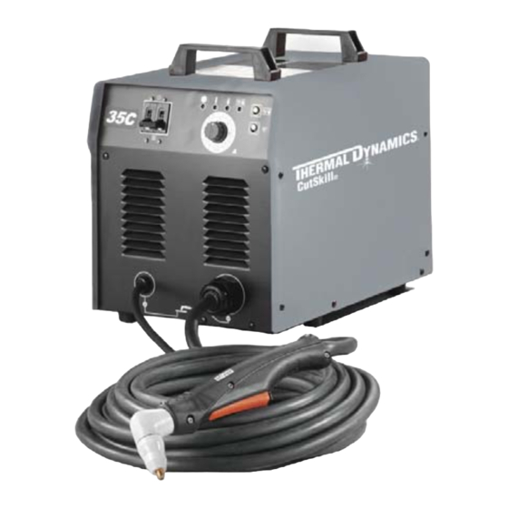
C-35C CUTSKILL ® PLASMA CUTTING SYSTEM Art # A-09400 Service Manual Rev. AB Date: November 17, 2009 Manual 0-4745 Operating Features: PLASMA... - Page 3 (603) 298-5711 www.thermal-dynamics.com ©Copyright 2006, 2007, 2008, 2009 by Thermal Dynamics Corporation All rights reserved. Reproduction of this work, in whole or in part, without written permission of the publisher is prohibited. The publisher does not assume and hereby disclaims any liability to any party for any loss or damage caused by any error or omission in this Manual, whether such error results from negligence, accident, or any other cause.
-
Page 5: Table Of Contents
TABLE OF CONTENTS SECTION 1: GENERAL INFORMATION ....................1-1 1.01 Notes, Cautions and Warnings ..............1-1 1.02 Important Safety Precautions ............... 1-1 1.03 Publications ....................1-2 1.04 Declaration of Conformity ................1-4 1.05 Statement of Warranty .................. 1-5 SECTION 2.0 INTRODUCTION ...................... - Page 6 TABLE OF CONTENTS (Con't) Appendix 1: Operating Sequence, Block Diagram ..............A-1 Appendix 2: Torch Connection ....................A-2 Appendix 3: Microchip Pin-Out ....................A-3 Appendix 4: System Schematic 230V CE ................. A-4 Appendix 5: System Schematic 230V ..................A-6 GLOBAL CUSTOMER SERVICE CONTACT INFORMATION ......Inside Rear Cover...
-
Page 7: General Information
SECTION 1: • Use an air-supplied respirator if ventilation is not adequate to remove all fumes and gases. GENERAL INFORMATION • The kinds of fumes and gases from the plasma arc depend on the kind of metal being used, coatings on the metal, and the different processes. -
Page 8: Publications
• Provide a fire watch when working in an area where fire hazards 1.03 Publications may exist. Refer to the following standards or their latest revisions for more infor- • Hydrogen gas may be formed and trapped under aluminum mation: workpieces when they are cut underwater or while using a water table. - Page 9 THAT HAVE HELD HAZARDOUS SUBSTANCES, obtainable from the American Welding Society, 550 N.W. LeJeune Rd, Miami, FL 33126 15. ANSI Standard Z88.2, PRACTICE FOR RESPIRATORY PRO- TECTION, obtainable from American National Standards Institute, 1430 Broadway, New York, NY 10018 • Montez et maintenez le matériel conformément au Code électrique national des Etats-Unis.
-
Page 10: Declaration Of Conformity
Rigorous testing is incorporated into the manufacturing process to ensure the manufac- tured product meets or exceeds all design specifications. Thermal Dynamics has been manufacturing products for more than 30 years, and will continue to achieve excellence in our area of manufacture. -
Page 11: Statement Of Warranty
1.05 Statement of Warranty LIMITED WARRANTY: Subject to the terms and conditions established below, Thermadyne ® Corporation warrants to the original retail purchaser that new Thermadyne CutSkill Series plasma cutting systems sold after the effective date of this warranty are free of defects in material and workmanship. Should any failure to conform to this warranty appear within the applicable period stated below, Thermadyne Corporation shall, upon notification thereof and substantiation that the product has been stored operated and maintained in accordance with Thermadyne’s specifications, instructions, recommendations and recognized industry practice, correct such defects by suitable repair or replacement. - Page 12 GENERAL INFORMATION Manual 0-4745...
-
Page 13: Introduction
SECTION 2.0 2.03 Features INTRODUCTION • COMPACT and LIGHT - Designed for easy trans- portation. • ENERGY EFFICIENCY - Advanced technology 2.01 INTRODUCTION reduces power consumption. • HIGH SPEED GENUINE CUTTING - The con- Plasma is a gas which has been heated to an extremely stricted plasma arc provides high speed cutting high temperature and ionized so that it becomes elec- as well as a good quality genuine, narrow cut. -
Page 14: Torch Specifications
2.04 Torch Specifications 2.05 System Contents 3 in Description ITEMS Q'ty (76.2 mm) Power source Model Drag-Gun Plus PCH-42, with 20' 10.5 in (266.7 mm) Art # A-04653 Torch Set (6.1 m) leads Work Cable Accessories & Manual Consumables Torch Electrodes Torch Tips PCH-42 Torch Ratings 3 Meter NEMA 10 AWG /... -
Page 15: Installation
3.03 Torch SECTION 3.0 INSTALLATION • Make sure that the torch cable and torch switch terminals are connected to front panel. • Make sure the Work Cable is connected properly 3.01 Site Selection to front panel. • Before activating, turn torch away from yourself •... - Page 16 This Page Left Blank Installation Manual 0-4745...
-
Page 17: Operation
B. BUTTONS SECTION 4.0 OPERATION • Torch Switch Latch Button - For 4.01 Front Control Panel continuous cutting performance. Depress this button ( turn “On” ) while cutting with the torch. Release the torch trigger and the torch will con- tinue to cut without depressing the torch trig- Air Error Indicator Overheating... -
Page 18: Preparations For Operating
D. Torch Operation 4.02 Preparations For Operating • Wear gloves and protective goggles. At the start of each operating session: • Do not place bare hand on work piece. 1. For drag cutting, keep the torch in contact with WARNING the workpiece. - Page 19 E. Typical Cutting Speeds Cutting speeds vary according to torch output, the type of material being cut, and operator skill. Speeds shown are typical for this cutting system using air plasma to cut mild steel, with output current at the highest setting and torch held at the indicated standoff height.
- Page 20 This Page Left Blank Operation Manual 0-4745...
-
Page 21: Section 5: Maintenance
SECTION 5: MAINTENANCE 5.01 General Maintenance Maintain more often Warning! if used under severe Disconnect input power before maintaining. conditions Each Use Visual check of torch tip and electrode Weekly Visually inspect the cables and leads. Replace as needed Visually inspect the torch body tip, electrode and shield cup 3 Months Replace all... - Page 22 This Page Left Blank Maintenance Manual 0-4745...
-
Page 23: Troubleshooting
SECTION 6: TROUBLESHOOTING 6.01 Normal Setup and Operation Connect the unit to power. Connect the work lead clamp to cleaned area of work surface. Turn the switch located on the front panel, to the "On" position. The A/C indicator on the front panel lights and the cooling fan comes on. -
Page 24: Basic Trouble Shooting Guide
6.02 Basic Trouble Shooting Guide Problem - Symptom Possible Cause Recommended Action Power Switch is on 1. Improper electrical connection. 1. Check input power source and fuse. Check input cable and but the A/C Indicator 2. System was overloaded. connections. does not light 3. -
Page 25: Control Pcb Indicators
6.03 Control PCB Indicators WARNING There are extremely dangerous voltage and power levels present inside this unit. Do not attempt to diagnose or repair unless you have had training in power electronics measurement and troubleshooting techniques. NOTE: All procedures are done with the cover removed. Turn the switch located on the front panel, to the "On"... -
Page 26: Open Circuit Voltage Check
6.04 Open Circuit Voltage Check Unplug the CN1 connector on the H/V (spark gap) PCB. Turn unit power on. Measure terminal TB2, Pins 1 and 3. It should be 230VAC. Measure output voltage on Input diode (+ and -). It should be 325VDC. Depress and hold the torch trigger for each of the following checks /steps, numbers 6 - 9. -
Page 27: Detailed Fault Finding / Error Indicators
6.05 Detailed Fault Finding / Error Indicators Problem Check / Test Recommended Action Air Indicator is on 1 - Check air and electrical connections 1 - If connections are good, return and or audible to the internal air compressor to an authorized service center for intermitant tone 2 - Control PCB faulty repair. - Page 28 Testing of diode modules requires a digital volt/ohmmeter that has a diode test scale. Remember that even if the diode module checks good, it may still be bad. If in doubt, replace the diode module. Remove AC power. Refer to Appendix 3 Wiring diagram. Locate the IGBT diode module to be tested.
- Page 29 Reverse the meter leads across the diode for reverse bias testing (refer to following figure). A properly function- ing diode will block in the reverse bias direction and depending on the meter function will indicate an open or “OL”. Art # A-00306 Reverse Bias Diode Not Conducting VR COM...
- Page 30 B. Component Tests WARNING Disconnect primary power at the source before taking any resistance checks. Input Diode Module Board Circuit Test a. Check Input Diode for short per schematic located in Appendix 4. IGBT Module Test a. With an ohmmeter set on the diode range remove P5 from the IGBT and make the following IGBT checks: Gate PCB J5 IGBT Check White + DD (1.020)
-
Page 31: Torch Tests
6.06 Torch Tests WARNING Disconnect primary power at the source before disassembling the power supply, torch, or torch leads. PIP and Torch Switch Adapter Check a. Disconnect input power from power supply. b. Confirm that the torch parts are in place and that they match the parts consumables label on the power supply cover. - Page 32 This Page Left Blank TROUBLE SHOOTING 6-10 Manual 0-4745...
-
Page 33: Parts List
Provide the power supply model number and serial number when ordering parts. If a product must be returned for service, contact your distributor. Materials returned without proper authoriza- tion will not be accepted. Contact Information Thermal Dynamics Technical Service Dept. Tel: 1-800-752-7622 (1-800-PLASMA2) Fax: 1-800-221-4401 e-mail address: tdc-tech@thermadyne.com... -
Page 34: Parts List Power Supply
7.01 Parts List Power Supply Item Number Quantity Description Catalog Number Cable Ground PG29 9-0382 Case, Front 9-0309 PCB-Front 9-7117 Circuit Breaker 9-7143 Cover Assembly 35C 9-0310 Cooling Fan 9-7163 Power Cord Strain Relief 9-0296 Case, Back 9-0311 Case, Top 9-0312 PCB-Control 9-7181... - Page 35 Manual 0-4745 PARTS LIST...
- Page 36 PARTS LIST Manual 0-4745...
- Page 37 This Page Left Blank Manual 0-4745 PARTS LIST...
-
Page 38: Replacement Hand Torch Parts With Ergonomic Handle
7.02 Replacement Hand Torch Parts With Ergonomic Handle Item # Description Catalog # Assembly, Basic Head 70° Head 9-8442 PIP (Parts - In - Place) Pins 9-5723 #6-32 x 3/16" Phillips Pan Head Screw See Note #6 Internal Star Washer See Note Ergonomic Handle, Split, with Trigger (includes items #5 - 12) 9-8076... - Page 39 13 & 14 11 & 12 Art # A-07061 Manual 0-4745 PARTS LIST...
- Page 40 This Page Left Blank PARTS LIST Manual 0-4745...
-
Page 41: Appendix 1: Operating Sequence, Block Diagram
Appendix 1: Operating Sequence, Block Diagram Primary Input Power "On" or Plugged in Power Supply On/Off Switch "On" More air flow is required Green Power Indicator "On" and Fan is Running for Torch to Pilot than to run the power supply. Compressor not functioning Air Set Switch "On"... -
Page 42: Appendix 2: Torch Connection
Appendix 2: Torch Connection Disconnect power and air. Lay unit Art # A-04695 on its side. Remove two screws and access plate. DETAIL Power Supply Adapter Connections Negative / Plasma Lead Pilot To Power Black Supply Adapter Orange Switch Green Torch White Switch... -
Page 43: Appendix 3: Microchip Pin-Out
Appendix 3: Microchip Pin-Out 40 Pin Microchip 9 10 11 12 Socket on 24 22 20 18 16 14 12 10 Control 23 21 19 17 15 13 11 9 10 11 12 Manual 0-4745 APPENDIX... -
Page 44: Appendix 4: System Schematic 230V Ce
Appendix 4: System Schematic 230V CE 230 VAC DIODE IGBT IGBT 230 VAC 230 VAC INPUT AC230V Inrush Filter PCB 1 PH No.40276005 230 VAC 50 Ω Bk,2 E1 G2 Ω TW TW TW TW Capacitor B W G R B W G R G4 E3 NOTE:... - Page 45 Current Sensor Main Transformer WORK No H.F. VC_1 O.C.V. 325 VD_1 Pilot 130 OU_1 OU_2 190VAC GN_1 Cutting 80-100 C/T 1 (See Sec. 6 OCV in Service Manual) Pilot Relay PILOT REACTOR Conduit Coil Ω TORCH Twisted 36VAC +12VDC VC_1 10k Ω...
-
Page 46: Appendix 5: System Schematic 230V
Appendix 5: System Schematic 230V 230 VAC DIODE IGBT IGBT 230 VAC 230 VAC INPUT AC230V Filter Board 1 PH No.40276003 230 VAC 50 Ω Bk,2 E1 G2 Ω TW TW TW TW Capacitor B W G R B W G R G4 E3 NOTE: Located on IGBT... - Page 47 Current Sensor Main Transformer WORK No H.F. VC_1 O.C.V. 325 VD_1 Pilot 130 OU_1 OU_2 190VAC GN_1 Cutting 80-100 C/T 1 (See Sec. 6 OCV in Service Manual) Pilot Relay PILOT REACTOR Conduit Coil Ω TORCH Twisted 36VAC +12VDC VC_1 10k Ω...
- Page 48 This Page Left Blank APPENDIX Manual 0-4745...
-
Page 49: Global Customer Service Contact Information
GLOBAL CUSTOMER SERVICE CONTACT INFORMATION Thermadyne USA Thermadyne Asia Sdn Bhd 2800 Airport Road Lot 151, Jalan Industri 3/5A Denton, Tx 76207 USA Rawang Integrated Industrial Park - Jln Batu Arang 48000 Rawang Selangor Darul Ehsan Telephone: (940) 566-2000 West Malaysia 800-426-1888 Telephone: 603+ 6092 2988 Fax: 800-535-0557... - Page 50 Corporate Headquarters 16052 Swingley Ridge Road Suite 300 St. Louis, MO 63017 Telephone: 636-728-3000 Email: TDCSales@Thermadyne.com www.thermadyne.com...
Need help?
Do you have a question about the CUTSKILL C-35C and is the answer not in the manual?
Questions and answers