Thermal Dynamics cutmaster 10mm Operating Manual
Hide thumbs
Also See for cutmaster 10mm:
- Service manual (128 pages) ,
- Operating manual (84 pages) ,
- Operating manual (78 pages)

Related Manuals for Thermal Dynamics cutmaster 10mm


Summary of Contents for Thermal Dynamics cutmaster 10mm
- Page 1 10mm CUTMASTER ™ PLASMA CUTTING SYSTEM Operating Manual Rev. AB Date: September 30, 2009 Manual # 0-5074 Operating Features: 208-...
- Page 2 1888, or visit us on the web at www.thermal-dynamics.com. This Operating Manual has been designed to instruct you on the correct use and operation of your Thermal Dynamics product. Your satisfaction with this product and its safe operation is our ultimate concern.
- Page 3 Manufacturer assumes no liability for its use. Plasma Cutting Power Supply CutMaster™ 10mm SL60 1Torch™ Operating Manual Number 0-5074 Published by: Thermal Dynamics Corporation 82 Benning Street West Lebanon, New Hampshire, USA 03784 (603) 298-5711 www.thermal-dynamics.com Copyright 2008 by Thermadyne Corporation All rights reserved.
- Page 4 This Page Intentionally Blank...
-
Page 5: Table Of Contents
TABLE OF CONTENTS SECTION 1:GENERAL INFORMATION ..................1-1 1.01 Notes, Cautions and Warnings ..............1-1 1.02 Important Safety Precautions ..............1-1 1.03 Publications ....................1-2 1.04 Note, Attention et Avertissement ..............1-3 1.05 Precautions De Securite Importantes ............1-3 1.06 Documents De Reference ................1-5 1.07 Declaration of Conformity ................1-6 1.08 Statement of Warranty ................1-7 SECTION 2 SYSTEM:INTRODUCTION .................2-1... - Page 6 TABLE OF CONTENTS SECTION 5 SYSTEM: SERVICE .....................5-1 5.01 General Maintenance .................5-1 5.02 Common Faults ..................5-6 5.03 Basic Troubleshooting Guide ..............5-6 SECTION 5 TORCH:SERVICE ....................5T-1 5T.01 General Maintenance ................5T-1 5T.02 Inspection and Replacement of Consumable Torch Parts .......5T-2 SECTION 6:PARTS LISTS.......................6-1 6.01 Introduction ....................6-1 6.02...
-
Page 7: Section 1:General Information
10mm SECTION 1: • The kinds of fumes and gases from the plasma arc depend on the kind of metal being used, coatings on the metal, and the GENERAL INFORMATION different processes. You must be very careful when cutting... -
Page 8: Publications
10mm • Do not cut or weld on containers that may have held combus- 1.03 Publications tibles. Refer to the following standards or their latest revisions for more • Provide a fire watch when working in an area where fire hazards information: may exist. -
Page 9: Note, Attention Et Avertissement
10mm 14. American Welding Society Standard AWSF4.1, RECOM- MENDED SAFE PRACTICES FOR THE PREPARATION FOR WELDING AND CUTTING OF CONTAINERS AND PIPING THAT FUMÉE et GAZ HAVE HELD HAZARDOUS SUBSTANCES, obtainable from the La fumée et les gaz produits par le procédé de jet de plasma peuvent American Welding Society, 550 N.W. - Page 10 10mm • Utilisez la nuance de lentille qui est suggèrée dans le recommenda- • Montez et maintenez le matériel conformément au Code électrique tion qui suivent ANSI/ASC Z49.1: national des Etats-Unis. (Voir la page 5, article 9.) Nuance Minimum Nuance Suggerée...
-
Page 11: Documents De Reference
10mm 1.06 Documents De Reference 14. Norme AWSF4.1 de l’Association Américaine de Soudage, RECOM- MANDATIONS DE PRATIQUES SURES POUR LA PRÉPARATION À Consultez les normes suivantes ou les révisions les plus récentes ayant LA COUPE ET AU SOUDAGE DE CONTENEURS ET TUYAUX AYANT été... -
Page 12: Declaration Of Conformity
Thermal Dynamics has been manufacturing products for more than 30 years, and will continue to achieve excellence in our area of manufacture. -
Page 13: Statement Of Warranty
This warranty is exclusive and in lieu of any warranty of merchantability or fitness for a particular purpose. Thermal Dynamics will repair or replace, at its discretion, any warranted parts or components that fail due to defects in material or workmanship within the time periods set out below. - Page 14 10mm This Page Intentionally Blank GENERAL INFORMATION Manual 0-5074...
-
Page 15: Section 2 System:introduction
Electronic copies of this manual can also be downloaded at no charge in Acrobat PDF format by going to the Thermal Dynamics web site listed below and clicking on Thermal Dynamics and then on the Literature link: http://www.thermal-dynamics.com Manual 0-5074... -
Page 16: Power Supply Specifications
Cable without plug, for 230VAC, 20-Amp Single-Phase input power. Output Current 20-30 Amps, continuously variable Power Supply Gas Filtering Ability Particulates to 20 Microns Cutmaster 10mm Power Supply Duty Cycle (Note 2) Ambient Temperature 104° F (40° C) Duty Cycle DC Voltage... -
Page 17: Input Wiring Specifications
Provide clearance for proper air fl ow through the power supply. Operation without proper air fl ow will inhibit proper cooling and reduce duty cycle. 2.05 Input Wiring Specifi cations Cutmaster 10mm Input Power Requirements Input Power Input Current Input... -
Page 18: Power Supply Options And Accessories
Combination of ambient air and gas stream through torch E. SL60 Torch Ratings (Refer to Note) NOTE Ratings shown apply to the SL60 Torch only. Refer to the Specifications chart on page 2T-1 for Cutmaster 10mm data. F. Plasma Power Supply Used With •... -
Page 19: Section 2 Torch:introduction
10mm SECTION 2 TORCH: 2T.03 Specifications INTRODUCTION A. Torch Configurations 1. Hand Torch, Model SL60 2T.01 Scope of Manual The hand torch head is at 75° to the torch handle. The hand torches include a torch handle and torch This manual contains descriptions, operating trigger assembly. -
Page 20: 04 Options And Accessories
10mm 2T.05 Introduction to Plasma H. Gas Requirements SL60 Torch Gas Specifications A. Plasma Gas Flow Gas (Plasma and Secondary) Compressed Air Plasma is a gas which has been heated to an ex- Operating Pressure 60 - 75 psi... - Page 21 10mm B. Gas Distribution The single gas used is internally split into plasma and secondary gases. The plasma gas flows into the torch through the negative lead, through the starter cartridge, around the electrode, and out through the tip orifice.
- Page 22 10mm This Page Intentionally Blank INTRODUCTION 2T-4 Manual 0-5074...
-
Page 23: Section 3: Installation
10mm SECTION 3: INSTALLATION 3.01 Unpacking 1. Use the packing lists to identify and account for each item. 2. Inspect each item for possible shipping damage. If damage is evident, contact your distributor and / or ship- ping company before proceeding with the installation. -
Page 24: Primary Input Power Connections
10mm 3.03 Primary Input Power Connections CAUTION Check your power source for correct voltage before plugging in or connecting the unit. The primary power source, fuse, and any extension cords used must conform to local electrical code and the recommended circuit protection and wiring requirements as specified in Section 2. - Page 25 10mm B. Check Air Quality To test the quality of air, put the RUN / SET switch in the SET (down) position, place a welding filter lens in front of the torch and turn on the gas. Any oil or moisture in the air will be visible on the lens.
-
Page 26: Torch Connections
Teflon tape as a thread sealer, as small particles of the tape may break off and block the small gas passages in the torch. 3.05 Torch Connections If necessary, connect the torch to the Power Supply. Connect only the Thermal Dynamics model SL60 Torch to this power supply. WARNING Disconnect primary power at the source before connecting the torch. -
Page 27: Section 4 System:operation
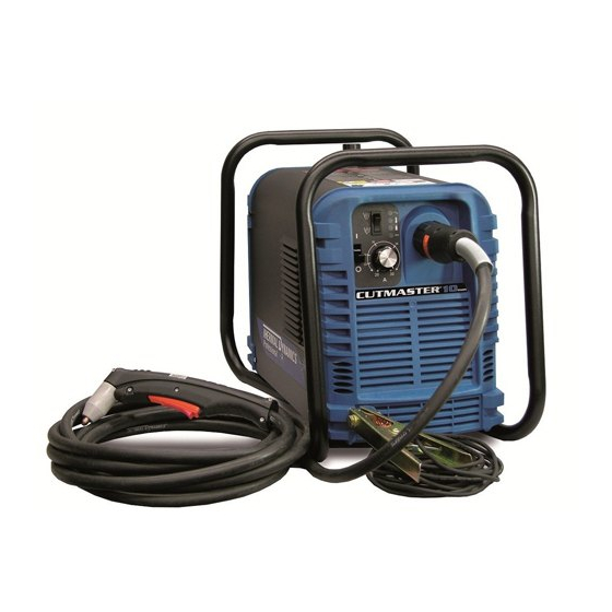
10mm SECTION 4 SYSTEM: OPERATION 4.01 Product Features A. General Features Handle and Leads Wrap Gas Pressure Knob Torch Leads Connector Art # A-07930 Control Panel Work Cable and Clamp Manual 0-5074 OPERATION... - Page 28 10mm B. Control Panel A-07931 1. ON / OFF Switch Controls input power to the power supply. Up is ON, down is OFF. 2. RUN / SET Switch RUN (up) position is for general torch operation. SET (down) position is for setting gas pressure and purging lines.
-
Page 29: Preparations For Operating
Check the torch for proper assembly and appropriate torch parts. The torch parts must correspond with the type of operation, and with the amperage output of this Power Supply (30 amps maximum). Use only genuine Thermal Dynamics parts with this torch. Art # A-03409_AB Large O-Ring, Cat. - Page 30 10mm D. Gas Selection Ensure gas source meets requirements (refer to Section 2). Check connections and turn gas supply on. E. Connect Work Cable Clamp the work cable to the workpiece or cutting table. The area must be free from oil, paint and rust. Connect only to the main part of the workpiece;...
- Page 31 10mm G. Set Operating Pressure Place the Power Supply RUN / SET switch to the SET (down) position. Gas will flow. Adjust gas pressure to 65 psi / 4.5 bar. Gas indicator turns on. NOTE If gas regulator leaks, reset gas pressure to 0 psi, then reset to 65 psi / 4.5 bar.
- Page 32 10mm Cutting Operation Refer to Section 1, Important Safety Precautions. Wear heavy welding gloves and protective clothing. Protect eyes with appropriate shielding. Aim the torch head away from yourself. Slide the trigger release to the rear. Squeeze and hold the trigger. Gas flows for approximately 1 second, then shuts off briefly. The pilot arc then starts.
-
Page 33: Sequence Of Operation
10mm 4.03 Sequence of Operation The following is a typical sequence of operation for this power supply. Refer to Appendix 1 for block diagram. 1. Plug the input power cord into an active circuit. a. AC power is available at the Power Supply. - Page 34 10mm This Page Intentionally Blank OPERATION Manual 0-5074...
-
Page 35: Section 4 Torch:operation
10mm SECTION 4 TORCH: NOTE Refer to Appendix Pages for additional informa- OPERATION tion as related to the Power Supply used. Power On 4T.01 Introduction Place the ON - OFF Switch on the Power Supply to This section provides a description of the SL60 the ON position. -
Page 36: 05 Cut Quality
10mm 4T.05 Cut Quality NOTE Refer to Section 6 and the Appendix Pages for NOTES additional information on torch parts. Cut quality depends heavily on setup and pa- Change the torch parts for a different operation as rameters such as torch standoff, alignment with... -
Page 37: 06 General Cutting Information
10mm Top - Edge Rounding Torch Standoff Rounding on the top edge of a cut due to wearing Improper standoff (the distance between the torch from the initial contact of the plasma arc on the tip and workpiece) can adversely affect tip life as workpiece. -
Page 38: 07 Hand Torch Operation
10mm b. For standoff cutting, hold the torch 1/8 Dross - 3/8 in (3-9 mm) from the workpiece as When dross is present on carbon steel, it is com- shown below. monly referred to as either “high speed, slow speed, or top dross”. - Page 39 10mm NOTE Drag Cutting With a Hand Torch The gas preflow and postflow are a characteristic Drag cutting works best on metal 3/16" (4.7 mm) of the power supply and not a function of the thick or less. torch.
- Page 40 10mm 7. Bring the torch within transfer distance to NOTE the work. The main arc will transfer to the The tip should never come in contact with the work, and the pilot arc will shut off. workpiece except during drag cutting opera- tions.
-
Page 41: 08 Recommended Cutting Speeds
10mm 4T.08 Recommended Cutting Speeds Cutting speeds vary according to torch output, the type of material being cut, and operator skill. Speeds shown are typical for this cutting system using air plasma to cut mild steel, with output current at 30 amps and torch held at 0 - 1/16"... - Page 42 10mm Optimum torch travel speed is dependent on current setting, lead angle, and mode of operation (hand or machine torch). Current Setting Current settings depend on torch travel speed, mode of operation (hand or machine torch), and the amount of material to be removed.
-
Page 43: Section 5 System: Service
10mm SECTION 5 SYSTEM: SERVICE 5.01 General Maintenance Warning! There are extremely dangerous voltage and power levels present inside this product. Do not attempt to open or repair unless you are a qualified electrical tradesperson and you have had training in power measurements Maintain more often and troubleshooting techniques. - Page 44 10mm A. Each Use Check torch consumables for wear, replace if necessary. WARNING Shut off power before inspecting or removing torch parts. NOTE When operating the torch in a normal condition, a small amount of gas vents through the gap between the shield cup and torch handle.
- Page 45 10mm B. Every three months A. Check internal air filter, replace if necessary. 1. Shut off input power; turn off the gas supply. Bleed down the gas supply. 2. Remove the upper cover screws. 3. Loosen the lower screws. Pull the cover up and away from the unit.
- Page 46 10mm 4. Pull the upper end of the drain tube off the fitting on the filter bowl 5. Unscrew the bowl. The filter element will be visible and still attached to the main body of the Regulator / Filter.
- Page 47 10mm C. O-Ring Lubrication D. Check Optional Single - Stage Filter Element, replace if necessary. An o-ring on the Torch ATC Male Connector requires lubrication on a regular basis, depending on how 1. Shut off input power. frequently the torch is disconnected and re-con- 2.
-
Page 48: Common Faults
4. Worn torch parts power levels present inside this unit. Do not 5. Cutting current too low. attempt to diagnose or repair unless you have 6. Non - Genuine Thermal Dynamics had training in power electronics measure- parts used ment and troubleshooting techniques. - Page 49 10mm B. AC indicator E. AC indicator flashing; Temp indicator 1. Switch at customer's main power panel in OFF (open) position. 1. Fan disconnected or blocked. a. Close main power switch. a. Clear fan if blocked; let power supply cool.
- Page 50 10mm 3. Faulty torch parts 3. Faulty components in unit a. Inspect torch parts and replace if necessary. a. Return for repair or have qualified technician repair per Service Manual. 4. Gas pressure too high or too low K. Erratic or improper cutting output a.
- Page 51 10mm 5. Torch consumables worn a. Check torch shield cup, tip, starter element, and electrode; replace as needed. 6. Faulty components in unit a. Return for repair or have qualified technician repair per Service Manual. N. No gas flow; AC indicator ON;...
- Page 52 10mm This Page Intentionally Blank SERVICE 5-10 Manual 0-5074...
-
Page 53: Section 5 Torch:service
10mm SECTION 5 TORCH: O-Ring Lubrication SERVICE An o-ring on the Torch ATC Male Connector requires lubrication on a scheduled basis. This will allow the o-ring to remain pliable and provide a proper seal. The o-ring will dry out, becoming hard and cracked, 5T.01 General Maintenance... -
Page 54: 02 Inspection And Replacement Of Consumable Torch Parts
10mm 5T.02 Inspection and Replacement 3. Remove the tip. Check for excessive wear (indi- cated by an elongated or oversized orifice). Clean of Consumable Torch Parts or replace the tip if necessary. Good Tip Worn Tip WARNINGS Disconnect primary power to the system before disassembling the torch or torch leads. -
Page 55: Section 6:Parts Lists
The following items are included with the replacement power supply: input power cord and plug, work cable & clamp, gas pressure regulator / filter, and operating manual. Description Catalog # Cutmaster 10mm CE Power Supply 3-4630 Cutmaster 10mm Non CE Power Supply 3-4631 Surelok Model SL60 Torch 7-5204 Cutmaster 10mm 230V CE Power Supply 3-4630-6 6.04 Power Supply Replacement Parts... -
Page 56: Options And Accessories
10mm 6.05 Options and Accessories Description Catalog # 230 V Input Power Cable 9-8671 Single - Stage Filter Kit (includes Filter & Hose) 7-7507 Replacement Filter Body 9-7740 Replacement Filter Hose (not shown) 9-7742 Replacement Filter Element 9-7741 Multi - Purpose Cart... -
Page 57: Torch Consumables
10mm 6.06 Torch Consumables Art # A-03409_AB Large O-Ring, Cat. No. 8-3487 Small O-Ring, Cat. No. 8-3486 Electrode, Cat. No. 9-8215 Start Cartridge, Cat. No. 9-8213 40 Amp Drag Tip, Cat. No. 9-8207 Shield Cup, Cat. No. 9-8218 Worn Electrode... - Page 58 10mm PARTS LISTS Manual 0-5074...
-
Page 59: Appendix 1: Sequence Of Operation(Block Diagram
10mm APPENDIX 1: SEQUENCE OF OPERATION (BLOCK DIAGRAM) ACTION ACTION ACTION ACTION ACTION ON / OFF switch Connect work cable Close external RUN / SET switch to SET. RUN / SET switch to ON. to RUN. to workpiece. disconnect switch. -
Page 60: Appendix 2: Data Tag Information
10mm APPENDIX 2: DATA TAG INFORMATION West Lebanon, NH USA 03784 Manufacturer's Name and/or Logo, Location, Model and Revision Level, Serial Number Model: and Production Code Date of Mfr: Made in USA Type of Power Regulatory Standard Covering Supply (Note 1) - Page 61 10mm This Page Intentionally Blank. Manual 0-5074 APPENDIX...
-
Page 62: Appendix 3: System Schematic
10mm APPENDIX 3: SYSTEM SCHEMATIC PFC INDUCTOR TEST +12VDC E12A E12A (E12A) E14A E14A (E1) (E14A) 208/230V 1PH FILTER 50/60HZ (E15A) (E16A) C70, 72, 81 C70, 72, 81 CE ONLY C71, 73, 75 C71, 73, 75 E15A E15A (E2) - Page 63 DWG No: DWG No: TITLE: TITLE: TITLE: 42X1324 42X1324 42X1324 CUTMASTER 10mm 208/230 1PH 50/60Hz CUTMASTER 10mm 208/230 1PH 50/60Hz CUTMASTER 10mm 208/230 1PH 50/60Hz Last Modified: Last Modified: Last Modified: Thursday, January 15, 2009 Thursday, January 15, 2009 Thursday, January 15, 2009...
- Page 64 10mm This Page Intentionally Blank. APPENDIX Manual 0-5074...
- Page 65 GLOBAL CUSTOMER SERVICE CONTACT Thermadyne USA Thermadyne Asia Sdn Bhd Lot 151, Jalan Industri 3/5A 2800 Airport Road Denton, Tx 76207 USA Rawang Integrated Industrial Park - Jln Batu Arang 48000 Rawang Selangor Darul Ehsan Telephone: (940) 566-2000 800-426-1888 West Malaysia Telephone: 603+ 6092 2988 Fax: 800-535-0557 Fax : 603+ 6092 1085...
- Page 66 Corporate Headquarters 16052 Swingley Ridge Road Suite 300 St. Louis, MO 63017 Telephone: 636-728-3000 Email: TDCSales@Thermadyne.com www.thermadyne.com...
Need help?
Do you have a question about the cutmaster 10mm and is the answer not in the manual?
Questions and answers