
Related Manuals for Thermal Dynamics CUTMASTER 12


Summary of Contents for Thermal Dynamics CUTMASTER 12
- Page 1 12mm CUTMASTER ™ PLASMA CUTTING SYSTEM Art # A-09205 Operating Manual Rev. AG Date: March 20, 2012 Manual # 0-5076 Operating Features: 380-...
- Page 2 1888, or visit us on the web at www.thermal-dynamics.com. This Operating Manual has been designed to instruct you on the correct use and operation of your Thermal Dynamics product. Your satisfaction with this product and its safe operation is our ultimate concern.
- Page 3 Manufacturer assumes no liability for its use. Plasma Cutting Power Supply CutMaster™ 12mm SL60 1Torch™ Operating Manual Number 0-5076 Published by: Thermal Dynamics Corporation 82 Benning Street West Lebanon, New Hampshire, USA 03784 (603) 298-5711 www.thermal-dynamics.com Copyright 2008, 2009, 2010, 2011, 2012 by Thermadyne Corporation All rights reserved.
- Page 4 This Page Intentionally Blank...
-
Page 5: Table Of Contents
TABLE OF CONTENTS SECTION 1: GENERAL INFORMATION .................1-1 1.01 Notes, Cautions and Warnings ..............1-1 1.02 Important Safety Precautions ..............1-1 1.03 Publications ....................1-2 1.04 Note, Attention et Avertissement ..............1-3 1.05 Precautions De Securite Importantes ............1-3 1.06 Documents De Reference ................1-5 1.07 Declaration of Conformity ................1-6 1.08 Statement of Warranty ................1-7... - Page 6 TABLE OF CONTENTS SECTION 5 SYSTEM: SERVICE .....................5-1 5.01 General Maintenance .................5-1 5.02 Maintenance Schedule ................5-2 5.03 Common Faults ..................5-2 5.04 Fault Indicator .....................5-3 5.05 Basic Troubleshooting Guide ..............5-4 5.06 Power Supply Basic Parts Replacement ............5-6 SECTION 5 TORCH: SERVICE .....................5T-1 5T.01 General Maintenance ................5T-1 5T.02...
-
Page 7: Section 1: General Information
CUTMASTER 12mm SECTION 1: GENERAL INFORMATION GASES AND FUMES Gases and fumes produced during the plasma cutting process can be 1.01 Notes, Cautions and Warnings dangerous and hazardous to your health. Throughout this manual, notes, cautions, and warnings are used to • Keep all fumes and gases from the breathing area. Keep your highlight important information. -
Page 8: Publications
CUTMASTER 12mm • Be sure there is no combustible or flammable material in the 1.03 Publications workplace. Any material that cannot be removed must be Refer to the following standards or their latest revisions for more protected. information: • Ventilate all flammable or explosive vapors from the workplace. 1. OSHA, SAFETY AND HEALTH STANDARDS, 29CFR 1910, • Do not cut or weld on containers that may have held combus- obtainable from the Superintendent of Documents, U.S. -
Page 9: Note, Attention Et Avertissement
CUTMASTER 12mm 1.04 Note, Attention et Avertissement Il faut communiquer aux opérateurs et au personnel TOUS les dangers possibles. Afin Dans ce manuel, les mots “note,” “attention,” et “avertissement” sont d’éviter les blessures possibles, lisez, compre- utilisés pour mettre en relief des informations à caractère important. nez et suivez tous les avertissements, toutes les Ces mises en relief sont classifiées comme suit : précautions de sécurité... - Page 10 CUTMASTER 12mm • Utilisez la nuance de lentille qui est suggèrée dans le recommen- • Ne touchez jamais une pièce “sous tension” ou “vive”; portez des dation qui suivent ANSI/ASC Z49.1: gants et des vêtements secs. Isolez-vous de la pièce de travail ou des autres parties du circuit de soudage. Nuance Minimum Nuance Suggerée Courant Arc Protective Numéro Numéro • Réparez ou remplacez toute pièce usée ou endommagée. Moins de 300* • Prenez des soins particuliers lorsque la zone de travail est humide ou moite.
-
Page 11: Documents De Reference
CUTMASTER 12mm 1.06 Documents De Reference 14. Norme AWSF4.1 de l’Association Américaine de Soudage, RECOM- MANDATIONS DE PRATIQUES SURES POUR LA PRÉPARATION À Consultez les normes suivantes ou les révisions les plus récentes ayant LA COUPE ET AU SOUDAGE DE CONTENEURS ET TUYAUX AYANT été faites à celles-ci pour de plus amples renseignements : RENFERMÉ DES PRODUITS DANGEREUX , disponible auprès de la American Welding Society, 550 N.W. LeJeune Rd., Miami, FL 1. OSHA, NORMES DE SÉCURITÉ DU TRAVAIL ET DE PROTECTION 33126 DE LA SANTÉ, 29CFR 1910, disponible auprès du Superintendent of Documents, U.S. Government Printing Office, Washington, D.C. 15. Norme ANSI Z88.2, PRATIQUES DE PROTECTION RESPIRATOIRE, 20402 disponible auprès de l’American National Standards Institute, 1430 Broadway, New York, NY 10018... -
Page 12: Declaration Of Conformity
* ISO/IEC 60974-1 (BS 638-PT10) (EN 60 974-1) (EN50192) (EN50078) applicable to plasma cutting equipment and associated accessories. * For environments with increased hazard of electrical shock, Power Supplies bearing the 'S' mark conform to EN50192 when used in conjunction with hand torches with exposed cutting tips, if equipped with properly installed standoff guides. * Extensive product design verification is conducted at the manufacturing facility as part of the routine design and manufacturing process. This is to ensure the product is safe, when used according to instructions in this manual and related industry standards, and performs as specified. Rigorous testing is incorporated into the manufacturing process to ensure the manufactured product meets or exceeds all design specifications. Thermal Dynamics has been manufacturing products for more than 30 years, and will continue to achieve excellence in our area of manufacture. Manufacturers responsible representative: Steve Ward Operations Director Thermadyne Europe Europa Building Chorley N Industrial Park... -
Page 13: Statement Of Warranty
This warranty is exclusive and in lieu of any warranty of merchantability or fitness for a particular purpose. Thermal Dynamics will repair or replace, at its discretion, any warranted parts or components that fail due to defects in material or workmanship within the time periods set out below. Thermal Dynamics Corporation must be notified within 30 days of any failure, at which time Thermal Dynamics Corporation... - Page 14 CUTMASTER 12mm This Page Intentionally Blank GENERAL INFORMATION Manual 0-5076...
-
Page 15: Section 2 System: Introduction
Acrobat PDF format INTRODUCTION by going to the Thermal Dynamics web site listed below and clicking on Thermal Dynamics and then on the 2.01 How To Use This Manual Literature link: This Owner’s Manual applies to just specification http://www.thermal-dynamics.com... -
Page 16: Power Supply Specifications
CUTMASTER 12mm 2.04 Power Supply Specifications CutMaster 12mm Power Supply Specifications 380 VAC (360 - 440 VAC), Three Phase, 50/60 Hz Input Power 400 VAC (360 - 440 VAC), Three Phase, 50/60 Hz NOTE: Some CutMaster 12mm models will only operate on 380-400V. Please check your † machine before attempting to run on any of the other voltages that are listed above. Power Supply includes input cable. -
Page 17: Input Wiring Specifications
CUTMASTER 12mm 2.05 Input Wiring Specifications CutMaster 12mm Power Supply Input Cable Wiring Requirements Input voltage Freq Power Input Suggested Sizes Flexible Cord Volts I max I eff Fuse (amps) (AWG) 50/60 3 Phase 50/60 Line Voltages with Suggested Circuit Protection and Wire Sizes Based on National Electric Code and Canadian Electric Code NOTE Refer to Local and National Codes or local authority having jurisdiction for proper wiring requirements. -
Page 18: Power Supply Features
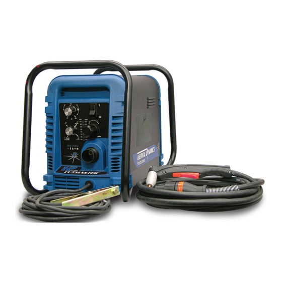
CUTMASTER 12mm 2.06 Power Supply Features Handle and Leads Wrap Control Panel Torch Leads Receptacle Art # A-07942 Work Cable and Clamp Port for Optional Automation Interface Cable Filter Assembly Gas Inlet Port Art # A-08544 Input Power Cord INTRODUCTION Manual 0-5076... -
Page 19: Section 2 Torch: Introduction
CUTMASTER 12mm SECTION 2 TORCH: 2T.03 Specifications INTRODUCTION A. Torch Configurations 1. Hand/Manual Torch, Models 2T.01 Scope of Manual The hand torch head is at 75° to the torch handle. The hand torches include a torch handle and torch This manual contains descriptions, operating trigger assembly. -
Page 20: 04 Options And Accessories
CUTMASTER 12mm 2T.05 Introduction to Plasma F. Torch Ratings Manual Torch Ratings A. Plasma Gas Flow Ambient 104° F Plasma is a gas which has been heated to an ex- Temperature 40° C tremely high temperature and ionized so that it Duty Cycle 100% @ 60 Amps @ 400 scfh becomes electrically conductive. - Page 21 CUTMASTER 12mm B. Gas Distribution E. Parts - In - Place (PIP) The single gas used is internally split into plasma The torch includes a 'Parts - In - Place' (PIP) circuit. and secondary gases. When the shield cup is properly installed, it closes a switch.
- Page 22 CUTMASTER 12mm This Page Intentionally Blank INTRODUCTION 2T-4 Manual 0-5076...
-
Page 23: Section 3 System: Installation
CUTMASTER 12mm SECTION 3 SYSTEM: 3.03 Primary Input Power Connections INSTALLATION 3.01 Unpacking CAUTION 1. Use the packing lists to identify and ac- Check your power source for correct voltage count for each item. before plugging in or connecting the unit. 2. -
Page 24: Gas Connections
CUTMASTER 12mm 4. Using a customer supplied four - conductor 3.04 Gas Connections input power cable for the voltage desired, Connecting Gas Supply to Unit strip back the insulation on the individual wires. The connection is the same for compressed air or 5. - Page 25 CUTMASTER 12mm Installing Optional Single - Stage Air Filter Installing Optional Two - Stage Air Filter Kit An optional filter kit is recommended for im- This optional two - stage air line filter is also proved filtering with compressed air, to keep for use on compressed air shop systems.
- Page 26 CUTMASTER 12mm Using High Pressure Air Cylinders When using high pressure air cylinders as the air supply: 1. Refer to the manufacturer’s specifications for installation and maintenance proce- dures for high pressure regulators. 2. Examine the cylinder valves to be sure they are clean and free of oil, grease or any foreign material.
-
Page 27: Section 3 Torch: Installation
2. Put the Function Control switch in the SET If necessary, connect the torch to the Power Sup- position. ply. Connect only the Thermal Dynamics model 3. Place a welding filter lens in front of the SL60 / Manual or SL100 / Mechanical Torch to torch and turn ON the air. - Page 28 CUTMASTER 12mm Pinch Block Assembly Square Workpiece A-02585 Mechanical Torch Set - Up 3. The proper torch parts (shield cup, tip, start cartridge, and electrode) must be installed for the type of operation. Refer to Section 4T.07, Torch Parts Selection for details. INSTALLATION 3T-2 Manual 0-5076...
-
Page 29: Section 4 System: Operation
CUTMASTER 12mm SECTION 4 SYSTEM: OPERATION 4.01 Front Panel Controls / Features See Illustration for numbering Identification 1. Output Current Control Sets the desired output current. Output settings up to 40 Amps may be used for drag cutting (with the torch tip contacting the workpiece) or standoff cutting. -
Page 30: Preparations For Operation
(10) minute period once the condition is cleared. Check that the torch is properly connected. Only Thermal Dynamics model SL60 / Manual or SL100 / Set Operating Pressure Mechanical Torches may be connected to this Power Supply. - Page 31 CUTMASTER 12mm Typical Cutting Speeds STANDOFF CutMaster 12mm Gas Pressure Settings Cutting speeds vary according to torch output am- perage, the type of material being cut, and operator Leads SL60 SL100 skill. Refer to Section 4T.08 and following for greater Length (Hand Torch) (Mechanized Torch)
- Page 32 CUTMASTER 12mm This Page Intentionally Blank OPERATION Manual 0-5076...
-
Page 33: Section 4 Torch: Operation
CUTMASTER 12mm 3. Install the replacement Electrode by push- SECTION 4 TORCH: ing it straight into the torch head until it OPERATION clicks. . Install the starter cartridge and desired tip for the operation into the torch head. 4T.01 Torch Parts Selection 5. -
Page 34: 03 General Cutting Information
CUTMASTER 12mm 4T.03 General Cutting Information Kerf Width Cut Surface Bevel Angle Spatter WARNING Disconnect primary power at the source be- Top Edge fore disassembling the power supply, torch, Rounding or torch leads. Frequently review the Important Safety Pre- Dross cautions at the front of this manual. -
Page 35: 04 Hand Torch Operation
CUTMASTER 12mm NOTE Left Side Cut Angle Right Side The tip should never come in contact with Cut Angle the workpiece except during drag cutting operations. 2. Depending on the cutting operation, do one of the following: a) For edge starts, hold the torch perpen- dicular to the workpiece with the front A-00512 of the tip on the edge of the workpiece... - Page 36 CUTMASTER 12mm NOTE The gas preflow and postflow are a charac- teristic of the power supply and not a func- tion of the torch. Trigger Shield Cup Standoff Guide Torch Tip Workpiece Art # A-04034 Shield Cup With Straight Edge Trigger Release The drag shield cup can be used with a non conduc- tive straight edge to make straight cuts by hand.
- Page 37 CUTMASTER 12mm 2. The torch can be comfortably held in one 8. Cut as usual. Simply release the trigger hand or steadied with two hands. Position assembly to stop cutting. the hand to press the Trigger on the torch 9. Follow normal recommended cutting handle.
-
Page 38: 05 Gouging
CUTMASTER 12mm 4T.05 Gouging WARNING Trigger Be sure the operator is equipped with proper gloves, clothing, eye and ear protection and that all safety precautions at the front of this Trigger Release manual have been followed. Make sure no A-02986 part of the operator’s body comes in con- 6. -
Page 39: 06 Mechanized Torch Operation
CUTMASTER 12mm 4T.06 Mechanized Torch Operation Current Setting Current settings depend on torch travel speed, Cutting With Mechanized Torch mode of operation (hand or machine torch), and the amount of material to be removed. The mechanized torch can be activated by remote control pendant or by a remote interface device Lead Angle such as CNC. - Page 40 CUTMASTER 12mm For optimum smooth surface quality, the travel speed should be adjusted so that only the leading edge of the arc column produces the cut. If the travel speed is too slow, a rough cut will be produced as the arc moves from side to side in search of metal for transfer.
-
Page 41: 07 Parts Selection For Manual And Mechanized Torch Cutting
CUTMASTER 12mm 4T.07 Parts Selection for Manual and Mechanized Torch Cutting Tips: Shield DRAG TIP Cup Body, Shield Cap, Deflector 9-8237 CUTTING 9-8243 20A 9-8205 30A 9-8206 Shield Cup 40A 9-8207 9-8218 60A 9-8252 O-Ring No. 8-3488 Shield Cap, Drag DRAG SHIELD 40A 9-8244 CUTTING... -
Page 42: 08 Recommended Cutting Speeds For Sl60 Torch With Exposed Tip
CUTMASTER 12mm 4T.08 Recommended Cutting Speeds for SL60 Torch With Exposed Tip Type Torch: SL60 With Exposed Tip Type Material: Mild Steel Type Plasma Gas: Air Type Secondary Gas: Single Gas Torch Thickness Output Amperage Speed (Per Minute) Standoff Plasma Gas Press Flow (CFH) Pierce Pierce Height... -
Page 43: 09 Recommended Cutting Speeds For Sl60 Torch With Shielded Tip
CUTMASTER 12mm 4T.09 Recommended Cutting Speeds for SL60 Torch With Shielded Tip Type Torch: SL60 With Shielded Tip Type Material: Mild Steel Type Plasma Gas: Air Type Secondary Gas: Single Gas Torch Thickness Output Amperage Speed (Per Minute) Standoff Plasma Gas Press Flow (CFH) Pierce Pierce Height... -
Page 44: Patent Information
CUTMASTER 12mm PATENT INFORMATION Plasma Cutting Torch Patents The following parts are covered under U.S. and Foreign Patents as follows: Catalog # Description Patent(s) 9-8215 Electrode US Pat No(s) 6163008; 6987238 Other Pat(s) Pending 9-8213 Cartridge US Pat No(s) 6903301; 6717096; 6936786; 6703581;... - Page 45 CUTMASTER 12mm Catalog # Description Patent(s) 9-8245 Shield Cap US Pat No(s) 6914211; D496951 Other Pat(s) Pending The following parts are also licensed under U.S. Patent No. 5,120,930 and 5,132,512: Catalog # Description 9-8235 Shield Cap 9-8236 Shield Cap 9-8237 Shield Cup 9-8238 Shield Cap...
- Page 46 CUTMASTER 12mm This Page Intentionally Blank OPERATION 4T-14 Manual 0-5076...
-
Page 47: Section 5 System: Service
CUTMASTER 12mm SECTION 5 SYSTEM: SERVICE 5.01 General Maintenance Maintain more often Warning! if used under severe Disconnect input power before maintaining. conditions Each Use Visual check of torch tip and electrode Weekly Visually inspect the cables and leads. Replace as needed Visually inspect the torch body tip, electrode, start cartridge and shield cup 3 Months... -
Page 48: Maintenance Schedule
4. Worn torch parts environment. 5. Cutting current too low. Daily Operational Checks or Every Six Cutting 6. Non - Genuine Thermal Dynamics Hours: parts used 7. Incorrect gas pressure Check torch consumable parts, replace if damaged Main Arc 1. -
Page 49: Fault Indicator
CUTMASTER 12mm 5.04 Fault Indicator At initial power up, two lights will temporarily illu- minate for 2-3 seconds to show the version of software used. To determine the first digit, count the function indicators left to right, 1 through 5. To determine the second digit count the pressure indicators, reading from bottom to top, 0 through 7. -
Page 50: Basic Troubleshooting Guide
CUTMASTER 12mm 5.05 Basic Troubleshooting Guide WARNING There are extremely dangerous voltage and power levels present inside this unit. Do not attempt to diagnose or repair unless you have had training in power electronics measurement and troubleshooting techniques. Problem - Symptom Possible Cause Recommended Action ON / OFF Switch 1. - Page 51 CUTMASTER 12mm Problem - Symptom Possible Cause Recommended Action FAULT & 80 PSI 1. Torch shield cup is loose. 1. Tighten shield cup by hand. Do not overtighten. indicators flashing. 2. Torch tip, electrode or starter 2. Turn OFF power supply. Remove shield cup. Install Gas flow is cycling cartridge missing. missing parts. ON and OFF. 3. Torch start cartridge is stuck. 3. Turn OFF power supply. Bleed down system pressure.
-
Page 52: Power Supply Basic Parts Replacement
CUTMASTER 12mm 5.06 Power Supply Basic Parts C. Filter Element Assembly Replacement Replacement The Filter Element Assembly is in the rear panel. For better system performance, the filter element should be checked per the Maintenance Schedule (Subsection 5.02), and either cleaned or replaced. WARNING 1. - Page 53 CUTMASTER 12mm Optional Single-Stage Filter Element 5. Remove the fitting from the filter element as- sembly by inserting a 6 mm hex wrench into Replacement the internal hex fitting and turning it counter These instructions apply to power supplies where the clock-wise (left).
- Page 54 CUTMASTER 12mm Optional Two-Stage Filter Element Replacement The Two-Stage Air Filter has two Filter Elements. When the Filter Elements become dirty the Power Supply will continue to operate but cut quality may become unac- ceptable. Refer to Section 6, Parts List, for replacement filter element catalog number.
-
Page 55: Section 5 Torch: Service
CUTMASTER 12mm SECTION 5 TORCH: SERVICE Upper Groove 5T.01 General Maintenance with Vent Holes Must Remain Open NOTE Upper O-Ring in Correct Groove Refer to Previous "Section 5 System" for com- mon and fault indicator descriptions. Threads Lower O-Ring Cleaning Torch Art # A-03725 Torch Head O-Ring Even if precautions are taken to use only clean air... -
Page 56: 02 Inspection And Replacement Of Consumable Torch Parts
CUTMASTER 12mm 5T.02 Inspection and Replacement 4. Remove the tip. Check for excessive wear (indi- cated by an elongated or oversized orifice). Clean of Consumable Torch Parts or replace the tip if necessary. Good Tip Worn Tip WARNING Disconnect primary power to the system be- fore disassembling the torch or torch leads. -
Page 57: Section 6: Parts Lists
CUTMASTER 12mm SECTION 6: PARTS LISTS 6.01 Introduction A. Parts List Breakdown The parts list provide a breakdown of all replaceable components. The parts lists are arranged as follows: Section "6.03 Power Supply Replacement" Section "6.04 Replacement Power Supply Parts" Section "6.05 Options and Accessories"... -
Page 58: Replacement Power Supply Parts
CUTMASTER 12mm 6.04 Replacement Power Supply Parts Description Catalog # Regulator 9-0115* Filter Assembly Replacement Element 9-0116 Input Power Cord for 400 V Power Supply 9-0218 NOTE *9-0115 regulator, If the serial number of the power supply is prior to #05078755 then kit number 9-0201 will be needed to replace not only the regulator (9-0115) but the logic PCB as well. -
Page 59: Replacement Parts For Hand Torch
CUTMASTER 12mm 6.06 Replacement Parts for Hand Torch Item # Description Catalog # Torch Handle Replacement Kit (includes items No. 2 & 3) 9-7030 Trigger Assembly Replacement Kit 9-7034 Handle Screw Kit (5 each, 6-32 x 1/2” cap screw, and wrench) 9-8062 Torch Head Assembly Replacement Kit (includes items No. 5 & 6) 9-8219 Large O-Ring 8-3487 Small O-Ring 8-3486 Leads Assemblies with ATC connectors (includes switch assemblies) SL60, 20 - foot Leads Assembly with ATC connector... -
Page 60: Replacement Parts - For Machine Torches With Unshielded Leads
CUTMASTER 12mm 6.07 Replacement Parts - for Machine Torches with Unshielded Leads Item No. Qty Description Catalog No. Torch Head Assembly without leads (includes items 2, 3, and 14) 9-8220 Large O-Ring 8-3487 Small O-Ring 8-3486 PIP Switch Kit 9-7036 Unshielded Automated Leads Assemblies with ATC connectors 5 - foot / 1.5 m Leads Assembly with ATC connector 4-7850... - Page 61 CUTMASTER 12mm 5 & 6 A-07994_AB Manual 0-5076 PARTS LIST...
-
Page 62: Replacement Shielded Machine Torch Leads Assemblies
CUTMASTER 12mm 6.08 Replacement Shielded Machine Torch Leads Assemblies Item No. Qty Description Catalog No. Mechanized Shielded Leads Assemblies with ATC Connectors 5 - foot / 1.5 m Leads Assembly with ATC Connector 4-7846 10 - foot / 3.05 m Leads Assembly with ATC Connector 4-7847 25 - foot / 7.6 m Leads Assembly with ATC Connector 4-7848 50 - foot / 15.2 m Leads Assembly with ATC Connector 4-7849 Remote Pendant Adapter is Torch Continuity present on Mechanized leads only. ('PIP') Switch A-03684 PARTS LIST... -
Page 63: Torch Consumable Parts (Sl60)
CUTMASTER 12mm 6.09 Torch Consumable Parts (SL60) Tips: Shield DRAG TIP Cup Body, Shield Cap, Deflector 9-8237 CUTTING 9-8243 20A 9-8205 30A 9-8206 Shield Cup 40A 9-8207 9-8218 60A 9-8252 O-Ring No. 8-3488 Shield Cap, Drag DRAG SHIELD 40A 9-8244 CUTTING Shield Cup Body,... -
Page 64: Torch Consumable Parts (Sl100)
CUTMASTER 12mm 6.10 Torch Consumable Parts (SL100) Ohmic Clip Automation Torch Ohmic Clip 9-8224 Manual Torch 9-8259 20-40A Shield Tip: Shield Cap, Machine Cup Body, STANDOFF 40A 9-8245 9-8237 CUTTING 9-8205 Shield Cap, Deflector Shield Cup 9-8206 9-8243 9-8218 9-8208 Drag Shield Cup 9-8235 50-60A... -
Page 65: Appendix 1: Sequence Of Operation (Block Diagram
CUTMASTER 12mm APPENDIX 1: SEQUENCE OF OPERATION (BLOCK DIAGRAM) ACTION: ACTION: ACTION: ACTION: RUN / Rapid Auto Restart / ON / OFF switch to ON Close external RUN / SET / LATCH disconnect switch. Rapid Auto Restart / switch to RUN RESULT: SET / LATCH switch RESULT:... -
Page 66: Appendix 2: Data Tag Information
CUTMASTER 12mm APPENDIX 2: DATA TAG INFORMATION Manufacturer's Name and/or West Lebanon, NH USA 03784 Logo, Location, Model and Revision Level, Serial Number M odel : and Production Code Dat e of M f r : Made in USA Type of Power Regulatory Standard Covering 1/ 3 Supply (Note 1) -
Page 67: Appendix 3: Torch Pin - Out Diagrams
CUTMASTER 12mm APPENDIX 3: TORCH PIN - OUT DIAGRAMS A. Hand Torch Pin - Out Diagram ATC Female Receptacle ATC Male Connector Front View Front View Negative / Negative / Plasma Plasma 8 - Open 8 - Ground 4 - Green / Switch 4 - Switch 7 - Open... -
Page 68: Appendix 4: Torch Connection Diagrams
CUTMASTER 12mm APPENDIX 4: TORCH CONNECTION DIAGRAMS A. Hand Torch Connection Diagram Torch: SL60 / SL100 Hand Torch Leads: Torch Leads with ATC Connector Power Supply: with ATC Receptacle Male ATC Leads ATC Female Receptacle Power Connector Torch Torch Supply Head Leads Black... - Page 69 CUTMASTER 12mm This Page Intentionally Blank Manual 0-5076 APPENDIX...
-
Page 70: Appendix 5: System Schematic, 380/400/415V Units
CUTMASTER 12mm APPENDIX 5: SYSTEM SCHEMATIC, 380/400/415V UNITS PRI 1 PRI 1 PRI 2 PRI 2 PRI 4 PRI 4 PRI 3 PRI 3 BIAS SUPPLY MTH1 MTH1 MTH2 MTH2 +12VDC + C1-C4* + C1-C4* CHOKE /INRUSH CE UNITS ONLY MTH4 MTH4 MTH3... - Page 71 St Louis, MO 63017 USA St Louis, MO 63017 USA Date: Date: Date: Information Proprietary to THERMAL DYNAMICS CORPORATION. Information Proprietary to THERMAL DYNAMICS CORPORATION. Information Proprietary to THERMAL DYNAMICS CORPORATION. Thursday, March 27, 2008 Thursday, March 27, 2008 Thursday, March 27, 2008 Not For Release, Reproduction, or Distribution without Written Consent.
- Page 72 CUTMASTER 12mm This Page Intentionally Blank APPENDIX Manual 0-5076...
- Page 73 CUTMASTER 12mm This Page Intentionally Blank Manual 0-5076 APPENDIX...
-
Page 74: Appendix 6: Publication History
CUTMASTER 12mm APPENDIX 6: Publication History Cover Date Rev. Change(s) Sept. 26, 2008 Manual released. May 27, 2009 Updated 400V/600V schematic in appendix per ECOB1399 Feb. 25, 2010 Updated CNC cable part numbers in section 6 per ECOB1637. Sept. 14, 2010 Updated SL-100 consumables art in section 6 per ECOB1819. - Page 75 This Page Intentionally Blank...
- Page 76 Printed in: Mexico U.S. Customer Care: 800-426-1888 / 800-535-0557 Canada Customer Care: 905-827-4515 / 800-588-1714 • International Customer Care: 940-381-1212 / 940-483-8178 www.thermal-dynamics.com • A Global Cutting & Welding Market Leader ™ W O R L D H E A D Q U A R T E R S : 1 6 0 5 2 S w i n g l e y R i d g e R o a d , S u i t e 3 0 0 •...
Need help?
Do you have a question about the CUTMASTER 12 and is the answer not in the manual?
Questions and answers