
Related Manuals for Thermal Dynamics C-20A Cutskill


Summary of Contents for Thermal Dynamics C-20A Cutskill
-
Page 1: Service Manual
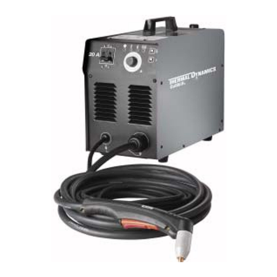
C-20A CUTSKILL ® PLASMA CUTTING SYSTEM Service Manual Rev. AA.01 Issue Date: March 26, 2007 Manual 0-4697 Operating Features: PLASMA... - Page 3 (603) 298-5711 www.thermal-dynamics.com ©Copyright 2005, 2006, 2007 by Thermal Dynamics Corporation All rights reserved. Reproduction of this work, in whole or in part, without written permission of the publisher is prohibited. The publisher does not assume and hereby disclaims any liability to any party for any loss or damage caused by any error or omission in this Manual, whether such error results from negligence, accident, or any other cause.
-
Page 5: Table Of Contents
TABLE OF CONTENTS SECTION 1: GENERAL INFORMATION ....................1-1 1.01 Notes, Cautions and Warnings ..............1-1 1.02 Important Safety Precautions ............... 1-1 1.03 Publications ....................1-2 1.04 Statement of Warranty .................. 1-4 SECTION 2: INTRODUCTION ....................... 2-1 2.01 Overview ...................... 2-1 2.02 General Specifications .................. -
Page 7: General Information
SECTION 1: GASES AND FUMES GENERAL INFORMATION Gases and fumes produced during the plasma cutting process can be dangerous and hazardous to your health. 1.01 Notes, Cautions and Warnings • Keep all fumes and gases from the breathing area. Throughout this manual, notes, cautions, and warnings Keep your head out of the welding fume plume. -
Page 8: Publications
• Never touch any parts that are electrically “live” or “hot.” PLASMA ARC RAYS • Wear dry gloves and clothing. Insulate yourself from the work piece or other parts of the welding circuit. Plasma Arc Rays can injure your eyes and burn your skin. •... - Page 9 6. ANSI Standard Z49.2, FIRE PREVENTION IN THE USE OF CUTTING AND WELDING PROCESSES, ob- tainable from American National Standards Institute, 1430 Broadway, New York, NY 10018 7. AWS Standard A6.0, WELDING AND CUTTING CONTAINERS WHICH HAVE HELD COMBUS- TIBLES, obtainable from American Welding Society, 550 N.W.
-
Page 10: Statement Of Warranty
1.04 Statement of Warranty LIMITED WARRANTY: Subject to the terms and conditions established below, Thermadyne ® Corporation warrants to the original retail purchaser that new Thermadyne CutSkill Series plasma cutting systems sold after the effective date of this warranty are free of defects in material and workmanship. -
Page 11: Introduction
SECTION 2: INTRODUCTION 2.01 Overview Plasma is a gas which has been heated to an extremely high temperature and ionized so that it becomes elec- trically conductive. The plasma arc cutting process uses this plasma to transfer an electrical arc to the work- 30% (3 min) piece. -
Page 12: Torch Ratings
If you have questions or concerns regarding your sys- stream through torch tem, please contact: Built-in Switch Parts-in-Place: in Torch Head Thermal Dynamics Technical Service Dept. Single Gas, Gas Requirement: Compressed Air Only Tel: 1-800-752-7622 (1-800-PLASMA2) 65 psi (4.5 bar) -
Page 13: Installation
Connect the input power cord as follows: SECTION 3: 1. Check the power source for correct voltage before INSTALLATION plugging in the unit. 2. Connect the input power cable (or close the main 3.01 Site Selection disconnect switch) to supply power to the system. 3.03 Compressed Air Connection •... - Page 14 This Page Left Blank Installation Manual 0-4697...
-
Page 15: Operation
B. Buttons SECTION 4: OPERATION • Torch Switch Latch Button 4.01 Front Control Panel For continuous cutting performance. Depress this button ( turn “On” ) while cutting with the torch. Release the torch trigger and the torch Air Error Indicator will continue to cut without depressing the torch Overheating Torch Switch... -
Page 16: Preparations For Operating
D. Torch Operation 4.02 Preparations For Operating • Refer to Section 1 for necessary safety precau- At the start of each operating session: tions. WARNING Trigger Disconnect primary power at the source before assembling or disassembling power supply, torch parts, or torch and leads assemblies. Trigger Release A. - Page 17 E. Typical Cutting Speeds Cutting speeds vary according to torch output, the type of material being cut, and operator skill. Speeds shown are typical for this cutting system using air plasma to cut mild steel, with output current at the highest setting and the torch used in the Drag mode only.
- Page 18 This Page Left Blank Operation Manual 0-4697...
-
Page 19: Section 5: Maintenance
SECTION 5: MAINTENANCE 5.01 General Maintenance Maintain more often Warning! if used under severe Disconnect input power before maintaining. conditions Each Use Visual check of Visual check of regulator and pressure torch tip and electrode Weekly Visually inspect the cables and leads. Replace as needed Visually inspect the torch body tip, electrode and shield cup... -
Page 20: Maintenance - Torch O-Rings
5.02 Maintenance - Torch O-Rings O-rings on the Torch require lubrication on a regular basis, depending on how frequently the torch shield cup is disconnected and re-connected. This will allow the O-rings to remain pliable and provide a proper seal. The O-rings will dry out, becoming hard and cracked, if the O-ring lubricant is not used on a regular basis. -
Page 21: Troubleshooting
SECTION 6: TROUBLESHOOTING WARNING There are extremely dangerous voltage and power levels present inside this unit. Do not attempt to diagnose or repair unless you have had training in power electronics measurement and troubleshooting techniques. NOTE: All procedures are done with the cover removed. 6.01 Setup and Operation Connect the unit to air supply and power. -
Page 22: Basic Trouble Shooting Guide
6.02 Basic Trouble Shooting Guide Problem - Symptom Possible Cause Recommended Action Power Switch is on 1. Improper electrical connection. 1. Check input power source and fuse. Check input cable and but the A/C Indicator 2. System was overloaded. connections. does not light 3. -
Page 23: Control Pcb Indicators
6.03 Control PCB Indicators Turn the switch located on the front panel, to the "On" position. The A/C indicator on the front panel should light. Locate the Control PCB behind the front panel. LD2 (EN) LED should be "ON". Control PCB Press the Air Set Button . -
Page 24: Open Circuit Voltage Check
6.04 Open Circuit Voltage Check Attach shop air to unit. Remove torch consumables from torch head and replace the shield cup. Turn unit power on. Measure terminal TB2, Pins 1 and 3. It should be 115VAC or 220VAC depending on input. Measure output voltage on bridge diode (red and black). - Page 25 A. Diode Testing Basics WARNING Disconnect primary power at the source before disassembling the power supply, torch, or torch leads. Testing of diode modules requires a digital volt/ohmmeter that has a diode test scale. Remember that even if the diode module checks good, it may still be bad. If in doubt, replace the diode module. 1.
- Page 26 6. Reverse the meter leads across the diode for reverse bias testing (refer to following figure). A properly functioning diode will block in the reverse bias direction and depending on the meter function will indicate an open or “OL”. Art # A-00306 Reverse Bias Diode Not Conducting VR COM...
- Page 27 B. Component Tests WARNING Disconnect primary power at the source before taking any resistance checks. 1. Input Diode Module Board Circuit Test Check Input Diode for short per schematic located in Appendix 4. 2. IGBT Module Test With an ohmmeter set on the diode range remove P5 from the IGBT and make the following IGBT checks: Gate PCB J5 IGBT Check DD (1.020) Open After Charging...
-
Page 28: Torch Tests
6.06 Torch Tests WARNING Disconnect primary power at the source before disassembling the power supply, torch, or torch leads. 1. PIP and Torch Switch Adapter Check Disconnect input power from power supply. Confirm that the torch parts are in place and that they match the parts consumables label on the power supply cover. -
Page 29: Parts List
Provide the power supply model number and serial number when ordering parts. If a product must be returned for service, contact your distributor. Materials returned without proper authorization will not be accepted. Contact Information Thermal Dynamics Technical Service Dept. Tel: 1-800-752-7622 (1-800-PLASMA2) Fax: 1-800-221-4401 e-mail address: tdc-tech@thermadyne.com... - Page 30 7.01 Parts List Power Supply Item Number Quantity Description Catalog Number Cable Ground PG29 9-0382 Case, Front 9-0323 Circuit Breaker 9-7176 PCB-Front 9-7117 Cover Assembly 9-0293 Solenoid Assembly 9-0294 Cover, Back 9-0295 Cable Ground PG21 9-0296 Air Assembly 9-0297 Cooling Fan 9-7163 Connector 9-0305...
- Page 31 Art # A-07744 Art # A-07745 Manual 0-4697 Parts List...
-
Page 32: Replacement Hand Torch Parts
7.02 Replacement Hand Torch Parts Item # Description Catalog # Torch Handle Replacement Kit (include items no. 2 & 3) 9-7030 Trigger Assembly Replacement Kit 9-7034 Handle Screw Kit (5 each, #6-32 x 1/2" cap screw, and wrench) 9-8062 Torch Head Assembly Replacement Kit (includes items No. 5 & 6) 9-8219 Large O-Ring 8-3487... - Page 33 A-07060 Manual 0-4697 Parts List...
- Page 34 This Page Left Blank Parts List Maual 0-4697...
-
Page 35: Appendix 1: Operating Sequence, Block Diagram
Appendix 1: Operating Sequence, Block Diagram Primary Input Power "On" or Plugged in Power Supply On/Off Switch "On" Green Power Indicator "On" and Fan is Running More air flow is required for Torch to Pilot than to Red Air Indicator Air Set Switch "On"... -
Page 36: Appendix 2: Torch Connection
Appendix 2: Torch Connection Art # A-04445 Disconnect power and air. Lay unit on its side. Remove access plate. DETAIL Negative / Plasma Lead Power Supply Adapter Pilot Work Cable Negative / Plasma Lead To Power Black Supply Adapter Switch Orange Green Torch... -
Page 37: Appendix 3: Microchip Pin-Out
Appendix 3: Microchip Pin-Out 40 Pin Microchip 9 10 11 12 Socket on 24 22 20 18 16 14 12 10 Control 23 21 19 17 15 13 11 9 10 11 12 Manual 0-4697 APPENDIX... -
Page 38: Appendix 4: System Schematic
Appendix 4: System Schematic 337VDC at 115VAC input 115VAC 298VDC at 220VAC input 220VAC IGBT IGBT INPUT Filter Board AC115/230V 1 PH No.40279012 INPUT DIODE From 230VAC Input Capcitor Filter Board E1 G2 Black to Input Diode Black to Red to Red to IGBT IGBT... - Page 39 Current Sensor Main Transformer WORK VC_1 VD_1 OU_1 OU_2 207VAC at 115VAC input 239VAC at 115VAC input 335VAC at 115VAC input O.C.V. 182VAC at 220VAC input GN_1 210VAC at 220VAC input 291VAC at 220VAC input C/T 1 Pilot 90 Cutting 110 Pilot Relay PILOT...
- Page 40 This Page Left Blank APPENDIX Manual 0-4697...
-
Page 41: Global Customer Service Contact Information
GLOBAL CUSTOMER SERVICE CONTACT INFORMATION Thermadyne USA Thermadyne Asia Sdn Bhd 2800 Airport Road Lot 151, Jalan Industri 3/5A Denton, Tx 76207 USA Rawang Integrated Industrial Park - Jln Batu Arang 48000 Rawang Selangor Darul Ehsan Telephone: (940) 566-2000 West Malaysia 800-426-1888 Fax: 800-535-0557 Telephone: 603+ 6092 2988... - Page 42 Corporate Headquarters 16052 Swingley Ridge Road Suite 300 St. Louis, MO 63017 Telephone: 636-728-3000 Email: TDCSales@Thermadyne.com www.thermadyne.com...
Need help?
Do you have a question about the C-20A Cutskill and is the answer not in the manual?
Questions and answers