
Related Manuals for Powertronix PTX 2 M Series


Summary of Contents for Powertronix PTX 2 M Series
-
Page 1: User Manual
POWERTRONIX spa User Manual PTX 2 M Series UPS 6/10 kVA www.powertronix.it POWERTRONIX spa Via Abruzzi,1 - 20056 Grezzago ( ITALY ) -
Page 2: Table Of Contents
4.4 Recycling the Used Battery ................. 21 5. Troubleshooting ....................22 LCD ......................22 LED ......................24 6. Appendix ......................27 6.1 Specifications....................27 General Specification ..................27 Battery Run Time..................288 6.2 Contact Information................... 29 POWERTRONIX . January 2006... -
Page 3: User Manual 6/10 Kva Rev
Adjust only those controls that are listed by the Adjustment Section. If the unit does not operate normally by following the operating instructions, contact the sales representatives. Icon Usage These icons may be found in the contents. WARNING: Obvious danger to personnel or equipment. CAUTION: Possible danger to personnel or equipment Important information POWERTRONIX . -ii- January 2006... - Page 4 USE OF THIS PRODUCT, EVEN IF ADVISED OF THE POSSIBILITY OF SUCH DAMAGE. Specifically, POWERTRONIX is not liable for any costs, such as lost profits or revenue, loss of equipment, loss of use of equipment, loss of software, loss of data, costs of substitutes, claims by third parties or otherwise.
-
Page 5: Presentation
USB, AS-400 or SNMP/HTTP card. Light weight unit Optional external battery slot for long runtime requirement DSP Technology Parallel redundancy capability Application: Computers Network Servers Workstations Wireless Communication Other Electronic Peripherals POWERTRONIX . - Page 1 of Total 29 - January 2006... -
Page 6: System Configuration
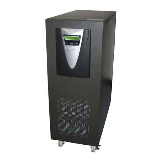
User manual 6/10 kVA Rev.2 1. Presentation 1.2 System Configuration 6kVA: 260W x 717H x 570D mm / 90 kgs 10kVA: 260W x 717H x 570D mm / 93 kgs POWERTRONIX . - Page 2 of Total 29 - January 2006... -
Page 7: Front Panel
4. Bypass LED (yellow) 5. Fault LED (red) 6. Inverter LED (green) 7. Select-up button 8. Select-down button 9. Enter button 7-8. Off button 8-9. On button & Test/Silence button POWERTRONIX . - Page 3 of Total 29 - January 2006... -
Page 8: Rear Panel
1. Communication ports: Standard RS232 Port & DB9, USB, AS400, SNMP/HTTP (Option) 2. Fan 3. Input Breaker 4. Inlet & Outlet (Terminal Block) 5. Maintenance Bypass Switch 6. External Battery Slot (Option) 7. Parallel port POWERTRONIX . - Page 4 of Total 29 - January 2006... -
Page 9: Extended Battery Bank
User manual 6/10 kVA Rev.2 1. Presentation Extended Battery Bank POWERTRONIX . - Page 5 of Total 29 - January 2006... -
Page 10: Installation
1. UPS 2. User Manual 3. 25-pin Serial Communication cable (Option for parallel units only) 4. External Battery Cable for long runtime units (Option: 3-port for 6kVA, 5-port for 10kVA) POWERTRONIX . - Page 6 of Total 29 - January 2006... -
Page 11: Installation
UPS is not charged first. Please calculate the capacity of UPS to include start-up of currents of any necessary inductance loads such as monitor and printer, etc. POWERTRONIX . - Page 7 of Total 29 - January 2006... -
Page 12: External Battery
(2) Connect the external battery with the proper external battery cable as shown pictures above. (3) After making connections, double check the wiring is correct and wires are secure. POWERTRONIX . - Page 8 of Total 29 - January 2006... -
Page 13: Parallel
(11) *WARNING* -AC and DC voltages can still be present on the terminal blocks even with the mains supply disconnected. Always check with a multi-meter before handling cables or connections. POWERTRONIX . - Page 9 of Total 29 - January 2006... -
Page 14: Connection To Communication
Received data Transmitted data Signal Ground Signal Ground The RS-232 interface settings are as follows: Baud Rate 2400 bps Data Length 8 bits Stop Bit 1 bit Parity None POWERTRONIX . - Page 10 of Total 29 - January 2006... -
Page 15: Optional Interface Cards
PIN # Function explanation of DB9 UPS Fault Output Input Remote Shutdown Output UPS(+12VDC) Input Input 12VDC Bypass Mode Output Output Low Battery Output Normal Mode Utility Power Fault Output POWERTRONIX . - Page 11 of Total 29 - January 2006... -
Page 16: As400 Card
All shutdown events are configurable by the user. The shutdown software provides an orderly shutdown to prevent the abnormal shut-off of clients or servers. Please refer to the NetAgent II installation CD for more information. POWERTRONIX . - Page 12 of Total 29 - January 2006... -
Page 17: Operation
“UPS Status” will show on the display. The screen should go back to “UPS Status” if you do not push any buttons for 2 minutes. Display 1 - Welcome screen POWERTRONIX UPS On-Line UPS Display 2 - Input/Output Voltage and Frequency... - Page 18 OLD AC Fail: ALM Overload: 9 Display 10 – Bypass Voltage Setting Bypass Volt Set LO= 176V HI=253V Display 11 – Output Voltage/ Frequency Setting Volt/Freq Set 220 VAC 50 Hz POWERTRONIX . - Page 14 of Total 29 - January 2006...
-
Page 19: Led
No. 10 LED: 0-25 % (battery low level) No. 9 - 10 LEDs: 26-50 % No. 7 - 10 LEDs: 76-95 % No. 8 - 10 LEDs: 51-75 % No. 6 - 10 LEDs: 96-100 % POWERTRONIX . - Page 15 of Total 29 - January 2006... -
Page 20: Starting Up/ Shutting Down The Ups
Step 2: Press the “Select-down” & “Enter” buttons simultaneously to switch on UPS. The UPS will begin its start-up process. After entering the Battery Mode, the UPS is ready for operation. POWERTRONIX . - Page 16 of Total 29 - January 2006... -
Page 21: Operation Modes
The AC output comes from battery, passing through DC/AC inverter and static switch within the battery backup time. Bypass Mode Under the following conditions, the bypass will be enabled: 1.Overload 2.Inverter failure 3.Over-temperature POWERTRONIX . - Page 17 of Total 29 - January 2006... -
Page 22: Configuration Settings
The output frequency (50Hz or 60Hz) can be adjusted by the same key operation. Step 4. Once the correct voltage is selected, press the “Enter” key again to save the selection. Display 11 – Output Voltage/ Frequency Setting Volt/Freq Set Save? NO POWERTRONIX . - Page 18 of Total 29 - January 2006... -
Page 23: Bypass Voltage
LO (low range):176V+/- 20V, HI(high range):253V+/- 20V. Step 4. Once the value is confirmed, press the “Enter” key again to save the data. Display 10 – Bypass Voltage Setting Bypass Volt Set Save? POWERTRONIX . - Page 19 of Total 29 - January 2006... -
Page 24: Maintenance
Batteries should be checked every two to three months. If the batteries need replacing, please contact your sales representative to order a new battery. POWERTRONIX . - Page 20 of Total 29 - January 2006... -
Page 25: Replacing The New Battery
Refer to your local codes for disposal requirements. Do not open or damage the battery or batteries. Released electrolyte is harmful to the skin and eyes and it is toxic. POWERTRONIX . - Page 21 of Total 29 - January 2006... -
Page 26: Troubleshooting
<100%. 105 % Fault Warning Normal AC utility power is normal but UPS is overloaded up to 105%~130%. Warning LED lights up and the alarm beeps per 0.5 second. POWERTRONIX . - Page 22 of Total 29 - January 2006... - Page 27 6 hours, please charge the battery for 24 hours to UPS completely shut down. ensure the battery fully charged. POWERTRONIX . - Page 23 of Total 29 - January 2006...
-
Page 28: Led
“ON” position. The utility power is normal, but the UPS Maintain switch Please contact the Sales Representatives. can not turn in line loose mode POWERTRONIX . - Page 24 of Total 29 - January 2006... - Page 29 ON battery or the Check the battery or recharge the battery. button battery pack voltage is too low. UPS fault. Please contact the Sales Representatives. POWERTRONIX . - Page 25 of Total 29 - January 2006...
- Page 30 ● ● ● Continuously beep Parallel abnormal ● ● ● ● Continuously beep ●: Solid ON : Flash : LED display and alarm warning are dependent on other conditions. POWERTRONIX . - Page 26 of Total 29 - January 2006...
-
Page 31: Appendix
( at 1 meter from surface of unit ) Mechanical Dimensions 260 x 717 x 570 ( W x H x D mm ) Weight ( Net weight with Battery ) ( kgs ) POWERTRONIX . - Page 27 of Total 29 - January 2006... -
Page 32: Battery Run Time
+ 2 EB (80pcs) + 3 EB (120pcs) EB: External Battery Bank For 6kVA, using 7Ah/12VDC battery For 10kVA, using 9Ah/12VDC battery Indicates time not calculated, contact sales representative for details. POWERTRONIX . - Page 28 of Total 29 - January 2006... -
Page 33: Contact Information
User manual 6/10 kVA Rev.2 6. Appendix 6.2 Contact Information POWERTRONIX SpA Via Abruzzi, 1 - 20056 GREZZAGO MI, Italy Tel:+39-02 90968648 Fax:+39-02-90968658 E-mail:info@powertronix.it http://www.powertronix.it POWERTRONIX . - Page 29 of Total 29 - January 2006...
Need help?
Do you have a question about the PTX 2 M Series and is the answer not in the manual?
Questions and answers