Table of Contents
Advertisement
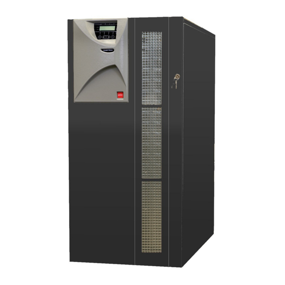
POWERTRONIX
UNINTERRUPTIBLE POWER SUPPLY
Document :
Revision
00
01-10-2007
01
22-10-2007
02
10/12/2008
POWERTRONIX SpA reserves the right to modify this document without any notice
R&D – PROCEDURA START-UP DT 0419 – E02
USER MANUAL
VELA 50-60 kVA
DT0419 English - Ptx
Date
Checked by
01-10-2007 Riccardo G.
22-10-2007 Gabriele P.
10/12/2008 Andrea P.
®
Approved by
01-10-2007 Andrea G.
Darek A.
22-10-2007 Andrea G.
10/12/2008 Andrea G.
Pag. 1 di 41
Advertisement
Table of Contents

Related Manuals for Powertronix VELA 50-60 kVA


Summary of Contents for Powertronix VELA 50-60 kVA
-
Page 1: User Manual
Darek A. 22-10-2007 22-10-2007 Gabriele P. 22-10-2007 Andrea G. 10/12/2008 10/12/2008 Andrea P. 10/12/2008 Andrea G. POWERTRONIX SpA reserves the right to modify this document without any notice Pag. 1 di 41 R&D – PROCEDURA START-UP DT 0419 – E02... -
Page 2: Table Of Contents
MENU 2 : EVENTS HISTORY.........................26 MENU 3 : OPERATIVE LANGUAGE......................26 MENU 4: CLOCK..............................26 3.10 MENU 5 : UPS CONFIGURATION ......................26 POWERTRONIX SpA reserves the right to modify this document without any notice Pag. 2 di 41 R&D – PROCEDURA START-UP DT 0419 – E02... - Page 3 CASE OF THE FIRE ............................40 FAULTS RELATED TO THE LOAD........................40 SCHEDULED MAINTENANCE..........................41 ANNUAL MAINTENANCE ..........................41 SCHEDULED COMPONENTS REPLACEMENT..................41 POWERTRONIX SpA reserves the right to modify this document without any notice Pag. 3 di 41 R&D – PROCEDURA START-UP DT 0419 – E02...
-
Page 4: Ups General Info
(optional), especially when the UPS is installed in unmonitored areas. Refer to the chapters 1.2.5 - 1.2.6. POWERTRONIX SpA reserves the right to modify this document without any notice Pag. 4 di 41 R&D – PROCEDURA START-UP DT 0419 – E02... -
Page 5: Configurations And Optional Equipments
The standard transformer is three-phase/three-phase (or single-phase/single-phase or three-phase/single- phase) with 1:1 ratio, but it can be supplied with a different transformation ratio upon customer request. POWERTRONIX SpA reserves the right to modify this document without any notice Pag. 5 di 41... -
Page 6: Circuits For Remote Communication
The software is used to monitor and control parameters of one or more UPS units supplying the network (more info at page 22) POWERTRONIX SpA reserves the right to modify this document without any notice Pag. 6 di 41 R&D – PROCEDURA START-UP DT 0419 – E02... -
Page 7: Remote Panel
The remote E.P.O push-button provides the safe, remote way to fast and full disable the unit running in the event of an emergency (more info at page 22) POWERTRONIX SpA reserves the right to modify this document without any notice Pag. 7 di 41... -
Page 8: Operating Theory
The filtered, regenerated and stabilized mains voltage supplies the load through the UPS OUTPUT (l4) switch. Refer to the figure 1.5.1 POWERTRONIX SpA reserves the right to modify this document without any notice Pag. 8 di 41 R&D – PROCEDURA START-UP DT 0419 – E02... -
Page 9: Logic And Auxiliary Circuits
The panel is equipped with an LCD screen used to display the operating status of the UPS, the load and all types of measurement (see chapter 3) POWERTRONIX SpA reserves the right to modify this document without any notice Pag. 9 di 41... -
Page 10: Installation Instructions
Once this period of time has elapsed, temporarily hook the UPS up to the mains and run it for the time needed to recharge the batteries. POWERTRONIX SpA reserves the right to modify this document without any notice Pag. 10 di 41... -
Page 11: Ups Positioning
All the connections are located in the rear panel and can be reached by just removing the cover as shown on the fig. 2.4 POWERTRONIX SpA reserves the right to modify this document without any notice Pag. 11 di 41... - Page 12 For the cables connection according to the UPS configuration refer to fig.2.4 Fig. 2.5 CABLES INPUT POWERTRONIX SpA reserves the right to modify this document without any notice Pag. 12 di 41 R&D – PROCEDURA START-UP DT 0419 – E02...
-
Page 13: Room Specifications
20°C is normally recommended. (when the temperature rises above 20°, for each 10° higher the battery life drops by 50%) POWERTRONIX SpA reserves the right to modify this document without any notice Pag. 13 di 41... -
Page 14: Connections And Layout To The Mains
Standard mains BY-PASS BY-PASS RESERVE LINE RESERVE INPUT Standard mains BATTERY1 Standard reserve fig. 2.6 BATTERY CABINET POWERTRONIX SpA reserves the right to modify this document without any notice Pag. 14 di 41 R&D – PROCEDURA START-UP DT 0419 – E02... - Page 15 K1-K2: additional relays on the change-over contact coil supply DISTRIBUTION PANEL L1-RESERVE L2-RESERVE L3-RESERVE NEUT NEUTRAL L1-MAINS L2-MAINS L3-MAINS NEUTRAL fig. 2.6b POWERTRONIX SpA reserves the right to modify this document without any notice Pag. 15 di 41 R&D – PROCEDURA START-UP DT 0419 – E02...
- Page 16 The connections must be created using a flex cables with the section as recommended in a table below Ø Ø (KVA) A.C. (mm A.C. (A) D.C. (mm D.C. (A) 50 (KVA) 60 (KVA) POWERTRONIX SpA reserves the right to modify this document without any notice Pag. 16 di 41 R&D – PROCEDURA START-UP DT 0419 – E02...
-
Page 17: Ups Aux Connections
Communication board (cap. 2.7.1) Communication board Optional SNMP board Optional fig. 2.7 POWERTRONIX SpA reserves the right to modify this document without any notice Pag. 17 di 41 R&D – PROCEDURA START-UP DT 0419 – E02... -
Page 18: Remote Communication Board
2.8a RELAYS BOARD EXTERNAL CONNECTIONS LOW BATTERY MAINS NOT OK fig. 2.8b MANUAL BYPASS INVERTER ON POWERTRONIX SpA reserves the right to modify this document without any notice Pag. 18 di 41 R&D – PROCEDURA START-UP DT 0419 – E02... -
Page 19: Remote Panel (Optional)
EXT SUPPLY CS0118 Relay REMOTE Board PANEL NOTE: ON CS0118 COMMON TAGBLOCKS MUST BE LINKED TOGETHER 2,5,8,11 POWERTRONIX SpA reserves the right to modify this document without any notice Pag. 19 di 41 R&D – PROCEDURA START-UP DT 0419 – E02... -
Page 20: Ups Management Software
WARNING!! INADEQUATE EARTH CONNECTION MAY CAUSE A RISK OF ELECTRIC SHOCK TO PERSONNEL OR OF FIRE POWERTRONIX SpA reserves the right to modify this document without any notice Pag. 20 di 41 R&D – PROCEDURA START-UP DT 0419 – E02... -
Page 21: Control Panel
On the left side of the display there are two LEDs, the green one called “NORMAL” and a red one called “ALARM”. The actions of the LED are summarized in the table 3.1a POWERTRONIX SpA reserves the right to modify this document without any notice Pag. 21 di 41 R&D – PROCEDURA START-UP DT 0419 – E02... -
Page 22: Lcd Control Panel
Enables the change of interface language CLOCK Date and time settings UPS CONFIGURATION Measurements adjustments and relays board test Table 3.1b POWERTRONIX SpA reserves the right to modify this document without any notice Pag. 22 di 41 R&D – PROCEDURA START-UP DT 0419 – E02... -
Page 23: Ups States And Alarms Visualization
Controlled by another UPS in parallel system Table 3.3 * For units in parallel system only POWERTRONIX SpA reserves the right to modify this document without any notice Pag. 23 di 41 R&D – PROCEDURA START-UP DT 0419 – E02... -
Page 24: Measurements
Power save on\off output frequency 50/60Hz If no operation is performed for 3 minutes, the “UPS STATUS AND ALARMS” menu is displayed. POWERTRONIX SpA reserves the right to modify this document without any notice Pag. 24 di 41 R&D – PROCEDURA START-UP DT 0419 – E02... -
Page 25: Ups In Fault Conditions
BATTERY CHARGER FAILURE Battery charger doesn’t work properly or is not connected POWERTRONIX SpA reserves the right to modify this document without any notice Pag. 25 di 41 R&D – PROCEDURA START-UP DT 0419 – E02... -
Page 26: Menu 1: Ups Commands
This menu entry is used to configure and adjust measurements results presented on LCD display and to test the relays board. Access to this menu option has the authorized personnel only POWERTRONIX SpA reserves the right to modify this document without any notice Pag. 26 di 41 R&D – PROCEDURA START-UP DT 0419 – E02... -
Page 27: Instructions For The Ups
Also remember about the presence of potentially charged capacitors inside the converter It means that you must wait for at least 10 min. before accessing to the internal parts of the UPS. POWERTRONIX SpA reserves the right to modify this document without any notice Pag. 27 di 41... -
Page 28: Powertronix Spa Reserves The Right To Modify This Document Without Any Notice
ATTENTION All the operations described below can be executed by authorized electrician or qualified personnel only POWERTRONIX SpA reserves the right to modify this document without any notice Pag. 28 di 41 R&D – PROCEDURA START-UP DT 0419 – E02... -
Page 29: Ups Start-Up Procedure
It is suggested to simulate the short power failure to check the correct operation of the entire UPS / battery system. To perform this operation just open and then close the mains switch powering the UPS. POWERTRONIX SpA reserves the right to modify this document without any notice Pag. 29 di 41... -
Page 30: Instructions For Switching System To Manual By-Pass Mode
(covered with metal panel) where the input and output cables are connected, and - for few minutes - inverter DC and AC capacitors (also covered with metal panel). POWERTRONIX SpA reserves the right to modify this document without any notice Pag. 30 di 41... -
Page 31: Instructions For Return From Manual By-Pass Mode To Normal Operation
After checking the correct polarity of the batteries close the battery panel switch. It makes the connection between the batteries and the UPS circuits. POWERTRONIX SpA reserves the right to modify this document without any notice Pag. 31 di 41... -
Page 32: Instructions For Complete Shutdown Of The Ups
Obviously, hazardous voltages remain inside the UPS panel. To reset EPO mode, the complete UPS shut down procedure is required. POWERTRONIX SpA reserves the right to modify this document without any notice Pag. 32 di 41 R&D – PROCEDURA START-UP DT 0419 – E02... -
Page 33: Instructions For Turning On The Ups In Power Save Mode
It is suggested to simulate the short power failure to check the correct operation of the entire UPS / battery system. To perform this operation just open and then close the mains switch powering the UPS. POWERTRONIX SpA reserves the right to modify this document without any notice Pag. 33 di 41... -
Page 34: Instructions For Switching System In Power Save Mode To Manual Bypass Mode
(covered with metal panel) where the input and output cables are connected, and - for few minutes - inverter DC and AC capacitors (also covered with metal panel). POWERTRONIX SpA reserves the right to modify this document without any notice Pag. 34 di 41... -
Page 35: Instructions For Return From Manual By-Pass Mode To Normal Operation In Power Save Mode
After checking the correct polarity of the batteries close the battery panel switch. It makes the connection between the batteries and the UPS circuits. POWERTRONIX SpA reserves the right to modify this document without any notice Pag. 35 di 41... -
Page 36: 4.11 Instructions For Completely Shutting Off The Ups In Power Save Mode
(covered with metal panel) where the input and output cables are connected, and - for few minutes - inverter DC and AC capacitors (also covered with metal panel). POWERTRONIX SpA reserves the right to modify this document without any notice Pag. 36 di 41... -
Page 37: 4.12 Managing The Ups Battery
In case of battery failure, the message “BATTERY TEST FAILED” will be displayed on the LCD. In this situation call the technical assistance centre. POWERTRONIX SpA reserves the right to modify this document without any notice Pag. 37 di 41... -
Page 38: Ups In Parallel
1.2.4 page 7 For additional information, see the attached technical report DT0367. (only for parallel systems) POWERTRONIX SpA reserves the right to modify this document without any notice Pag. 38 di 41 R&D – PROCEDURA START-UP DT 0419 – E02... -
Page 39: Troubleshooting
EMERGENCY BY-PASS and then leave the machine isolated and off. Call the technical assistance. POWERTRONIX SpA reserves the right to modify this document without any notice Pag. 39 di 41 R&D – PROCEDURA START-UP DT 0419 – E02... -
Page 40: Case Of The Fire
• The accuracy of the UPS output voltage is not optimal: this may depend on an excessively unbalanced and/or distorting load. POWERTRONIX SpA reserves the right to modify this document without any notice Pag. 40 di 41 R&D – PROCEDURA START-UP DT 0419 – E02... -
Page 41: Scheduled Maintenance
• All the power electrolyte capacitors need to be replaced every four years • The AC power capacitors need to be replaced every 6 years POWERTRONIX SpA reserves the right to modify this document without any notice Pag. 41 di 41...
Need help?
Do you have a question about the VELA 50-60 kVA and is the answer not in the manual?
Questions and answers