
Subscribe to Our Youtube Channel
Related Manuals for Hirschmann BXS


Summary of Contents for Hirschmann BXS
- Page 1 User Manual Installation Industrial Ethernet BOBCAT Extended Switch Installation BXS Technical support Release 01 04/2022 https://hirschmann-support.belden.com...
- Page 2 Control GmbH according to the best of the company's knowledge. Hirschmann reserves the right to change the contents of this document without prior notice. Hirschmann can give no guarantee in respect of the correctness or accuracy of the information in this document.
-
Page 3: Table Of Contents
Pin assignments Display elements 1.7.1 Device status 1.7.2 Port status Management interfaces 1.8.1 USB-M12-C interface Installation Checking the package contents Installing and grounding the device 2.2.1 Mounting on a flat surface 2.2.2 Grounding the device Installation BXS Release 01 04/2022... - Page 4 Climatic conditions during operation Climatic conditions during storage Dimension drawings Immunity Electromagnetic compatibility (EMC) Network range 7.9.1 10/100/1000 Mbit/s twisted pair port Scope of delivery Accessories General accessories Order numbers Underlying technical standards Further support Installation BXS Release 01 04/2022...
-
Page 5: Important Information
WARNING WARNING indicates a potentially hazardous situation which, if not avoided, could result in death or serious injury. CAUTION CAUTION indicates a possible danger which, if not avoided, may result in minor injuries. Installation BXS Release 01 04/2022... - Page 6 NOTICE NOTICE provides information about procedures that do not involve the risk of injury. Installation BXS Release 01 04/2022...
-
Page 7: Safety Instructions
Certified usage Use the product only for the application cases described in the Hirschmann product information, including this manual. Operate the product only according to the technical specifications. See “Technical data” on page 36. Connect to the product only components suitable for the requirements of the specific application case. - Page 8 The grounding screw is located on the front left bottom side of the device. See “Grounding the device” on page 28. Ground the device before connecting any other cables. Disconnect the grounding only after disconnecting all other cables. Installation BXS Release 01 04/2022...
- Page 9 Regarding the properties of this fuse: See “Technical data” on page 36. The negative conductors of the voltage inputs are on ground potential. Installation BXS Release 01 04/2022...
- Page 10 Directive of the European Parliament and of the Council on the characteristic value M9 or N9: harmonisation of the laws of the Member States relating to the making available on the market of electrical equipment designed for use within certain voltage limits. Installation BXS Release 01 04/2022...
- Page 11 In accordance with the above-named EU directive(s), the EU conformity declaration will be available to the relevant authorities at the following address: Hirschmann Automation and Control GmbH Stuttgarter Str. 45-51 72654 Neckartenzlingen Germany You find the EU conformity declaration as PDF file for downloading on the Internet at: https://www.doc.hirschmann.com/certificates.html...
- Page 12 Recycling note After usage, this device must be disposed of properly as electronic waste, in accordance with the current disposal regulations of your county, state, and country. Installation BXS Release 01 04/2022...
-
Page 13: About This Manual
Documentation mentioned in the “User Manual Installation” that is not supplied with your device as a printout can be found as PDF files for downloading on the Internet at: https://www.doc.hirschmann.com Installation BXS Release 01 04/2022... -
Page 14: Key
The symbols used in this manual have the following meanings: Listing Work step Subheading Installation BXS Release 01 04/2022... -
Page 15: Description
IEEE 802.3. The device provides you with a large range of functions, which the manuals for the operating software inform you about. You can download these manuals as PDF files from the Internet at: https://www.doc.hirschmann.com Installation BXS Release 01 04/2022... -
Page 16: Device Name And Product Code
24 V DC Rated voltage range 24 V DC ... 48 V DC Rated voltage range 72 V DC ... 110 V DC Rated voltage range 110 V AC ... 230 V AC Table 2: Product code Installation BXS Release 01 04/2022... -
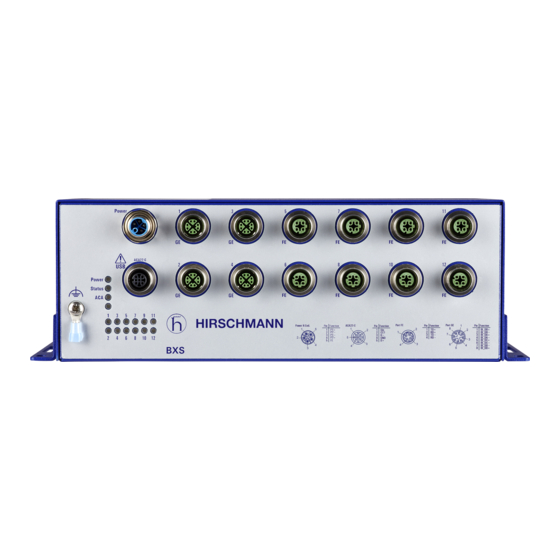
Page 17: Device Views
For PoE device variants: These ports support PoE (PoE+). LED display elements for port status Grounding screw LED display elements for device status USB-M12-C interface 5-pin, “A”-coded M12 socket Table 3: Front view Installation BXS Release 01 04/2022... -
Page 18: View From Below
1.3.2 View from below 1 ... 2 Slot hole for mounting on a flat surface Table 4: View from below Installation BXS Release 01 04/2022... -
Page 19: Power Supply
Supply voltage with the characteristic value M9 The following options for power supply are available: 5-pin, “K”-coded M12 plug You will find information on connecting the supply voltage here: See “Connecting the supply voltage” on page 29. Installation BXS Release 01 04/2022... -
Page 20: Ethernet Ports
Delivery state: Autonegotiation activated The port casing is electrically connected to the front panel. The pin assignment corresponds to MDI-X. Note: The twisted pair ports 1 ... 4 support full duplex only. See “Front view” on page 17. Installation BXS Release 01 04/2022... -
Page 21: Support Of Poe(+)
See “Technical data” on page 36. Note: Connect only PoE-powered devices whose data connections are located in the interior of the building and are specified as SELV circuits according to IEC 60950-1 or ES1 circuits according to IEC/EN 62368-1. Installation BXS Release 01 04/2022... -
Page 22: Pin Assignments
Figure 1: Pin assignments: Interfaces and ports Display elements 1.7.1 Device status These LEDs provide information about conditions which affect the operation of the whole device. Power Status Figure 2: LED display elements for device status Installation BXS Release 01 04/2022... - Page 23 ACA is not ready for operation — none Supply voltage is too low yellow lights up Supply voltage is too low for PoE support. green lights up PoE voltage is on Table 5: Meaning of the device display elements Installation BXS Release 01 04/2022...
-
Page 24: Port Status
3 × a period Port is switched off yellow flashing Device is transmitting and/or receiving data flashes 3 × a period The device deactivates the relevant port (auto-deactivation). Table 6: Meaning of the port display elements Installation BXS Release 01 04/2022... -
Page 25: Management Interfaces
The adapter cable is available as an accessory (see on page 47 “Accessories”). To connect the BXS device to an external device, perform the following work steps: Connect the adapter cable to the BXS device first. Connect the adapter cable to the external device next. - Page 26 Note: Exclusively connect adapter cables temporarily. Adapter cables may exclusively be used to configure, manage and check your device. Installation BXS Release 01 04/2022...
-
Page 27: Installation
Install the device with screws on a flat surface. Completely screw the device to the flat surface using screws through each mounting hole. Exclusively use screws suitable for the installation and application case to ensure flawless operation of the device. Installation BXS Release 01 04/2022... -
Page 28: Grounding The Device
Failure to follow this instruction can result in death, serious injury, or equipment damage. Perform the following work steps: Ground the device via the ground screw. Installation BXS Release 01 04/2022... -
Page 29: Connecting The Supply Voltage
Mount the power supply cable to the power supply connector of the device. You find the prescribed tightening torque in chapter: “Supply voltage” on page 36 Enable the supply voltage. Operating the device When you connect the supply voltage, you start up the device. Installation BXS Release 01 04/2022... -
Page 30: Connecting Data Cables
90° angle. Use shielded data cables, for example SF/UTP cables according to ISO/ IEC 11801. Connect the data cables according to your requirements. See “Ethernet ports” on page 20. Installation BXS Release 01 04/2022... -
Page 31: Making Basic Settings
The device provides the following options for configuring IP addresses: Input via the HiView or Industrial HiVision application. You find further information about the applications HiView or Industrial HiVision on the Internet at the Hirschmann product pages: HiView http://www.hirschmann.com/en/QR/INET-HiView Industrial HiVision http://www.hirschmann.com/en/QR/INET-Industrial-HiVision... - Page 32 Note: If you lost your password, then use the System Monitor to reset the password. For further information see: https://hirschmann-support.belden.com/en/kb/required-password-change- new-procedure-for-first-time-login Installation BXS Release 01 04/2022...
-
Page 33: Monitoring The Ambient Air Temperature
The maximum internal temperature of the device named in the technical data is a guideline that indicates to you that the maximum ambient air temperature has possibly been exceeded. Installation BXS Release 01 04/2022... -
Page 34: Maintenance And Service
Hirschmann is continually working on improving and developing their software. Check regularly whether there is an updated version of the software that provides you with additional benefits. You find information and software downloads on the Hirschmann product pages on the Internet (http://www.hirschmann.com). ... -
Page 35: Disassembly
Failure to follow these instructions can result in death, serious injury, or equipment damage. Perform the following work steps: Disable the supply voltage. Disconnect the data cables. Disconnect the power supply cable. Disconnect the grounding. Remove the screws. Installation BXS Release 01 04/2022... -
Page 36: Technical Data
Connection type 5-pin, “L”-coded M12 plug Tightening torque 0.6 Nm (5.3 lb-in) Wire diameter min. AWG20 (0.5 mm²) Power loss buffer >10 ms at 20.4 V DC Table 8: Supply voltage with characteristic value BB Installation BXS Release 01 04/2022... - Page 37 Voltage range DC incl. maximum 50.4 V DC ... 138 V DC tolerances: Rated voltage range for railway 72 V DC ... 110 V DC applications according to EN 50155 Table 10: Supply voltage with characteristic value N9 Installation BXS Release 01 04/2022...
- Page 38 BXS32/42 4 A ... 20 A Characteristic: slow blow Peak inrush current BXS30/40 <1 A BXS32/42 <4 A Current integral I²t BXS30/40 <0,1 A BXS32/42 <0.5 A²s Table 11: Supply voltage with characteristic value M9 Installation BXS Release 01 04/2022...
-
Page 39: Power Consumption/Power Output
25 W + 60 W PoE 85.2 Btu (IT)/h + 60 W PoE HV-2A EN9... – BXS42-000012- 25.5 W+ 60 W PoE 87.1 Btu (IT)/h + 60 W PoE EM9... Table 12: Power consumption/power output Installation BXS Release 01 04/2022... -
Page 40: Climatic Conditions During Operation
(-40 °F ... +158 °F) -40 °C ... +50 °C up to 2 years (-40 °F ... +122 °F) 0 °C ... +30 °C up to 10 years (+32 °F ... +86 °F) Table 14: Climatic conditions during storage Installation BXS Release 01 04/2022... -
Page 41: Dimension Drawings
700 hPa (+3000 m ASL; +9842 ft ASL) max. 1060 hPa (-400 m ASL; -1312 ft ASL) Table 14: Climatic conditions during storage Dimension drawings inch 143.6 9.92 5.65 11.1 10.71 Figure 5: Dimension drawings Installation BXS Release 01 04/2022... -
Page 42: Immunity
Immunity Immunity Standard applications Railway applications (trackside) Railway applications (on vehicles) IEC 60068-2-6, test Fc Vibration 5 Hz ... 8.4 Hz with 3.5 mm — Operating (0.14 in) amplitude 5 Hz ... 150 Hz, Broadband noise vertical: 1.0 m/s² (rms) horizontal: 0.7 m/s²... -
Page 43: Electromagnetic Compatibility (Emc)
Electromagnetic compatibility (EMC) EMC interference Standard applications Railway applications Railway applications emission (trackside) (on vehicles) Radiated emission EN 55032 Class A Class A Class A FCC 47 CFR Part 15 Class A Class A Class A EN 61000-6-4 Fulfilled Fulfilled Fulfilled EMV 06 Rev. - Page 44 EMC interference Standard applications Railway applications Railway applications immunity (trackside) (on vehicles) EN 61000-4-3 80 MHz ... 800 MHz 10 V/m 10 V/m 20 V/m 800 MHz ... 1000 MHz 10 V/m 20 V/m 20 V/m 1.4 GHz ... 2.0 GHz 3 V/m 10 V/m 10 V/m...
-
Page 45: Network Range
Network range 7.9.1 10/100/1000 Mbit/s twisted pair port 10/100/1000 Mbit/s twisted pair port Length of a twisted pair segment max. 100 m (328 ft) (for Cat5e cable) Table 18: Network range: 10/100/1000 Mbit/s twisted pair port Installation BXS Release 01 04/2022... -
Page 46: Scope Of Delivery
Scope of delivery Scope of delivery 1 × Device 1 × Safety and general information sheet 1 × M12 Power connector for crimp connections with wire diameter AWG16 (1.5 mm²) Table 19: Scope of delivery Installation BXS Release 01 04/2022... -
Page 47: Accessories
AutoConfiguration Adapter ACA22-M12-C (EEC) 942 306-001 M12-USB adapter cable (for connecting the ACA with a 942 199-001 computer) Adapter cable M12 5-pin to USB (for configuration of BXS 942 309-001 devices) Field attachable connector for the power supply, M12, “K”- 934 935-002 coded, for crimp connections with wire diameter AWG16 (1.5 mm²) -
Page 48: 10 Underlying Technical Standards
Table 22: List of the technical standards The device has an approval based on a specific standard exclusively if the approval indicator appears on the device casing. The device generally fulfills the technical standards named in their current versions. Installation BXS Release 01 04/2022... -
Page 49: A Further Support
Further support Technical questions For technical questions, please contact any Hirschmann dealer in your area or Hirschmann directly. You find the addresses of our partners on the Internet at http://www.hirschmann.com. A list of local telephone numbers and email addresses for technical support directly from Hirschmann is available at https://hirschmann-support.belden.com.
Need help?
Do you have a question about the BXS and is the answer not in the manual?
Questions and answers