Sign In
Upload
Manuals
Brands
Hirschmann Manuals
Switch
PowerLION-24TP
Hirschmann PowerLION-24TP Manuals
Manuals and User Guides for Hirschmann PowerLION-24TP. We have
1
Hirschmann PowerLION-24TP manual available for free PDF download: Installation Manual
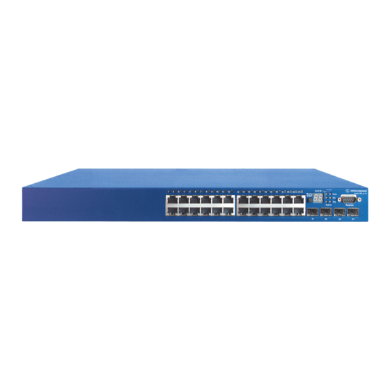
Hirschmann PowerLION-24TP Installation Manual (78 pages)
Gigabit ETHERNET Layer 3 Switch
Brand:
Hirschmann
| Category:
Switch
| Size: 2.63 MB
Table of Contents
Installation Guide
1
Japan VCCI Class a
5
Safety Compliance
7
Warnings and Cautionary Messages
10
Related Publications
11
Table of Contents
13
Chapter 1: Introduction
21
Overview
21
Figure 1-1 Powerlion-24TP Front Panel
21
Figure 1-2 Powerlion-24TP Rear Panel
22
Network Management Options
22
Switch Architecture
22
Description of Hardware
23
10/100/1000BASE-T Ports
23
SFP Slots
23
Stacking Ports
23
Port and System Status Leds
24
Table 1-1 Port Status Leds
24
Figure 1-3 Port Leds
24
Table 1-2 System Status Leds
25
Figure 1-4 System Leds
25
Optional Redundant Power Unit
26
Power Supply Sockets
26
Optional Media Extender Module
26
Figure 1-5 Power Supply Sockets
26
Figure 1-6 Single-Port 10G Module (Xenpak)
26
Extender Module Leds
27
Features and Benefits
27
Connectivity
27
Expandability
27
Table 1-3 Module Leds
27
Performance
28
Management
28
Chapter 2: Network Planning
29
Introduction to Switching
29
Application Examples
30
Collapsed Backbone
30
Figure 2-1 Collapsed Backbone
30
Network Aggregation Plan
31
Figure 2-2 Network Aggregation Plan
31
Remote Connections with Fiber Cable
32
Figure 2-3 Remote Connection with Fiber Cable
32
Making VLAN Connections
33
Figure 2-4 Making VLAN Connections
33
Using Layer 3 Routing
34
Figure 2-5 IP Routing for Unicast Traffic
34
Application Notes
35
Chapter 3: Installing the Switch
37
Selecting a Site
37
Ethernet Cabling
37
Equipment Checklist
38
Package Contents
38
Optional Rack-Mounting Equipment
38
Figure 3-1 RJ-45 Connections
38
Mounting
39
Rack Mounting
39
Figure 3-2 Attaching the Brackets
39
Desktop or Shelf Mounting
40
Figure 3-3 Installing the Switch in a Rack
40
Figure 3-4 Attaching the Adhesive Feet
40
Installing an Optional Module into the Switch
41
Figure 3-5 Installing an Optional Module
41
Installing an Optional SFP Transceiver
42
Connecting Switches in a Stack
42
Figure 3-6 Inserting an SFP Transceiver into a Slot
42
Figure 3-7 Making Stacking Connections
43
Stacking Topologies
44
Connecting to a Power Source
44
Figure 3-8 Power Receptacle
44
Connecting to the Console Port
45
Wiring Map for Serial Cable
45
Table 3-1 Serial Cable Wiring
45
Figure 3-9 Serial Port (DB-9 DTE) Pin-Out
45
Chapter 4: Making Network Connections
47
Connecting Network Devices
47
Twisted-Pair Devices
47
Cabling Guidelines
47
Connecting to Pcs, Servers, Hubs and Switches
48
Network Wiring Connections
48
Figure 4-1 Making Twisted-Pair Connections
48
Fiber Optic SFP Devices
49
Figure 4-2 Network Wiring Connections
49
10 Gbps Fiber Optic Connections
50
Figure 4-3 Making Connections to SFP Transceivers
50
Connectivity Rules
51
1000BASE-T Cable Requirements
51
Figure 4-4 Making SC Port Connection to Xenpak Transceiver
51
10 Gbps Ethernet Collision Domain
52
Table 4-1 Maximum 10GBASE-SR 10 Gigabit Ethernet Cable Length
52
Table 4-2 Maximum 10GBASE-ER 10 Gigabit Ethernet Cable Length
52
Table 4-3 Maximum 10GBASE-LR 10 Gigabit Ethernet Cable Length
52
1000 Mbps Gigabit Ethernet Collision Domain
53
100 Mbps Fast Ethernet Collision Domain
53
10 Mbps Ethernet Collision Domain
53
Table 4-4 Maximum 1000BASE-T Gigabit Ethernet Cable Length
53
Table 4-5 Maximum 1000BASE-SX Gigabit Ethernet Cable Length
53
Table 4-6 Maximum 1000BASE-LX Gigabit Ethernet Cable Length
53
Table 4-7 Maximum 1000BASE-LH Gigabit Ethernet Cable Length
53
Table 4-8 Maximum Fast Ethernet Cable Length
53
Table 4-9 Maximum Ethernet Cable Length
53
Cable Labeling and Connection Records
54
Appendix A: Troubleshooting
55
Diagnosing Switch Indicators
55
Diagnosing Power Problems with the Leds
55
Table A-1 Troubleshooting Chart
55
Table A-2 Power/Rpu Leds
55
Power and Cooling Problems
56
Installation
56
In-Band Access
56
Stack Troubleshooting
57
Appendix B: Cables
59
Twisted-Pair Cable and Pin Assignments
59
10BASE-T/100BASE-TX Pin Assignments
59
Figure B-1 RJ-45 Connector Pin Numbers
59
Straight-Through Wiring
60
Crossover Wiring
60
Table B-1 10/100BASE-TX MDI and MDI-X Port Pinouts
60
Figure B-2 Straight-Through Wiring
60
1000BASE-T Pin Assignments
61
Table B-2 1000BASE-T MDI and MDI-X Port Pinouts
61
Figure B-3 Crossover Wiring
61
Cable Testing for Existing Category 5 Cable
62
Adjusting Existing Category 5 Cabling to Run 1000BASE-T
62
Fiber Standards
62
Appendix C: Specifications
63
Physical Characteristics
63
Switch Features
64
Management Features
64
Standards
65
Compliances
65
Extender Modules
65
Xenpak Extender Module (Xenpak
65
Installationsort Auswählen
67
(Selecting a Site - German
67
Montage (Rack Mounting Instructions - German
68
Schaltschrank-Montage
68
Advertisement
Advertisement
Related Products
Hirschmann PowerMICE
Hirschmann PowerMICE Series
Hirschmann Pipetus
Hirschmann PTN-2-C37.94
Hirschmann PTN2206
Hirschmann PTN2210
Hirschmann Dragon PTN-1-10G-LW
Hirschmann Dragon PTN-4-GCB-LW
Hirschmann Pipetus Junior
Hirschmann PAT 050-350-061-355
Hirschmann Categories
Switch
Network Router
Control Unit
Wireless Access Point
Antenna
More Hirschmann Manuals
Login
Sign In
OR
Sign in with Facebook
Sign in with Google
Upload manual
Upload from disk
Upload from URL