
Related Manuals for Rangemaster Professional + FX Dual Fuel


Summary of Contents for Rangemaster Professional + FX Dual Fuel
- Page 1 � ������������ �� ArtNo.000-0025 - Professional + FX logo Dual Fuel User Guide & Installation & Service Instructions U110004 - 08...
-
Page 2: Table Of Contents
Contents Before You Start... Installation Installation and Maintenance Dear Installer Peculiar smells Provision of Ventilation If you smell gas Location of Cooker Ventilation Conversion Personal Safety Positioning the Cooker Cooker Care Moving the Cooker Cleaning Completing the Move Levelling Overview Fitting a Stability Bracket Hotplate Burners Gas Connection... -
Page 3: Before You Start
1. Before You Start... If you smell gas Thank you for buying this cooker. It should give you many years of trouble-free cooking if installed and operated • DO NOT turn electric switches on or off. correctly. It is important that you read this section before •... -
Page 4: Cooker Care
Cooking high moisture content In normal use, the cooling fan will operate when the oven or foods can create a ‘steam burst’ grill are in use. Should a fault occur with the fan switch off the when the oven door is opened. cooker immediately and contact your installer or service. -
Page 5: Overview
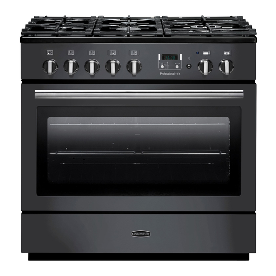
2. Overview DocNo.025-0101 - Overview - 90 DF SC - Prof+ FX Fig.2-1 � � Professional + FX � � ArtNo.270-0029 - Prof+ 90SC annotated The dual fuel single cavity cooker (Fig.2-1) has the following Fig.2-2 features: ArtNo.270-0001 Proplus control to high 5 hotplate burners including a wok burner A control panel incorporating a timer A multi-function oven... -
Page 6: Wok Burner
If, when you let go of the control knob, the burner goes out, Fig.2-3 then the FSD has not been bypassed. Turn the control knob ArtNo.270-0003 Proplus control to low to the OFF position and wait for one minute before you try again, this time making sure to hold in the control knob for slightly longer. -
Page 7: The Griddle
Make sure that the cradle is stable and that the Wok is sitting Fig.2-10 level in the ring. The cradle will get very hot in use – allow plenty of time for it to cool before you pick it up. The Griddle The griddle fits the left-hand well, front to back (Fig.2-11). - Page 8 Multi-function oven modes (Fig.2-13) Fig.2-13 ArtNo.270-0025 Defrost Proplus MF oven annotated � � This function operates the fan(s) to circulate cold air ArtNo.030-0028 - Elan MF symbols only. No heat is applied. This enables small items such as desserts, cream cakes and pieces of meat, fish and poultry to be defrosted.
-
Page 9: Energy Saving Feature
Conventional Oven (Top and Base Heat) This function combines the heat from the top and WARNING! Elan MF symbols base elements. It is particularly suitable for roasting Take great care when removing the divider NOT to and baking pastry, cakes and biscuits. scratch the inner glass door surface. -
Page 10: Operating The Oven
DO NOT place or slide metallic objects, including cookware, Fig.2-17 on the door glass as this may cause scratching and subsequent failure to occur. ArtNo.270-0026 Proplus MF oven controls (2) Operating the Oven The multi-function oven has two controls: a function selector and a temperature setting knob (Fig.2-17). - Page 11 Once the ‘stop time’ is reached, the beeper sounds. Turn the Fig.2-25 Fig.2-26 Timer knob to the vertical ( ) to return to manual cooking. ArtNo.301-0010 2BC ArtNo.301-0009 2BC To start and then stop the oven using the Timer Setting the cooking time Setting the cooking timer You cannot set a start time directly –...
-
Page 12: Accessories
Accessories Fig.2-33 Fig.2-34 Oven racks Each oven is supplied with: ArtNo.326-0013 - Full capacity shelf Two full capacity shelves (Fig.2-33) (Falcon) ArtNo.326-0004 - Cradle shelf Grill pan tray support (Fig.2-34) Two grill pans with trivets (Fig.2-35) Three energy saving shelves (Fig.2-36) Fig.2-35 Fig.2-36 Four ladder shelf supports (Fig.2-37) -
Page 13: Storage
Storage Fig.2-42 The bottom drawer is for storing oven trays and other cooking utensils. It can get very warm, so do not store anything in it that may melt or catch fire. Never store flammable materials in the drawer. This includes paper, plastic and cloth items, such as cookbooks, plastic ware and towels, as well as flammable ArtNo.281-0138 - Drawer pulled out liquids. -
Page 14: Cooking Tips
3. Cooking Tips Cooking with a Multi-function Oven General Oven Tips Remember: not all modes are suitable for all food types. The The wire shelves should always be pushed firmly to the back oven cooking times given are intended for a guide only. of the oven. -
Page 15: Cooking Table
4. Cooking Table DocNo.031-0004 - Cooking table - electric & fan single cavity The oven control settings and cooking times given in the table below are intended to be used AS A GUIDE ONLY. Individual tastes may require the temperature to be altered to provide a preferred result. -
Page 16: Troubleshooting
5. Troubleshooting Hotplate ignition or cooktop burners faulty If there is an installation problem and I don’t get my original installer to come back to fix it who pays? Is the power on? You do. Service organizations will charge for their call Are the sparker (ignition electrode) or burner holes outs if they are correcting work carried out by your blocked by debris? - Page 17 An oven light is not working Fig.5-1 The bulb has probably burnt out. You can buy a replacement bulb (which is not covered under the warranty) from a good electrical shop. Ask for a 15 W– 230 V lamp, FOR OVENS. It must be a special bulb, heat ArtNo.324-0005 Oven light bulb resistant to 300 °C (Fig.5-1).
-
Page 18: Cleaning Your Cooker
6. Cleaning Your Cooker Isolate the electricity supply before carrying out any major Fig.6-1 cleaning. Allow the cooker to cool. � Never use paint solvents, washing soda, caustic cleaners, biological powders, bleach, chlorine based bleach cleaners, coarse abrasives or salt. Do not mix different �... -
Page 19: Griddle
The Wok Burner Fig.6-2 ArtNo.311-0014 Wok burner details When reassembling the wok burner (Fig.6-2) turn over the � large base ring and find the ‘D’ shaped area (Fig.6-3). Turn the head until the ‘D’ matches the one on the burner base. Flip the burner over once again and place it on the burner base. -
Page 20: Cleaning Table
Cleaning Table Cleaners listed are available from supermarkets or electrical retailers as stated. For enamelled surfaces use a cleaner that is approved for use on vitreous enamel. The vitreous enamel association has a list of approved cleaners. Contact them via their website http://www.ive.org.uk/ or telephone: 01543... -
Page 21: Installation
7. Installation Dear Installer The cooker must be installed in accordance with: All relevant British Standards / Codes of Practice, in Before you start your installation, please complete the details particular BS 5440 Part 2 2000 below, so that, if your customer has a problem relating to your installation, they will be able to contact you easily. -
Page 22: Location Of Cooker
Location of Cooker Checking the Parts: The cooker may be installed in a kitchen/kitchen diner but Levelling tool & Allen keys Full capacity shelf NOT in a room containing a bath or shower. Note: An appliance for use on LPG must not be installed in a room or internal space below ground level, e.g. -
Page 23: Positioning The Cooker
Positioning the Cooker ArtNo.092-0003 - 90SC cooker min spacings Fig.7-1 The diagrams show the minimum recommended distance from the cooker to nearby surfaces (Fig.7-1). 75 mm 75 mm 650 mm The cooker should not be placed on a base. Above hotplate surround should be level with, or above, any adjacent work surface. -
Page 24: Completing The Move
Removing the Oven Door Fig.7-5 To remove the oven door, open the door fully. Swivel the locking ‘U’ clips forward to the locking position (Fig.7-5). Grip the sides of the door, lift upwards and then slide the door forwards (Fig.7-6). ArtNo.062-0001 - 90 Prof+ FX - Removing the door When you have removed the oven door continue as follows: First fit the levelling tool on the hexagonal adjusting nut... -
Page 25: Gas Connection
floor level to underside of the top member) and ensure � Fig.7-10 the bracket does not foul the oven burner assembly (Fig.7-10). Gas Connection Must be in accordance with the relevant standards. A hose is not supplied by with the cooker. Hoses may be purchased at most builders’... -
Page 26: Electrical Connection
Electrical Connection Fig.7-12 This appliance must be installed by a qualified electrician to comply with the relevant Institute of Electrical Engineers (I.E.E.) regulations, and also the local electricity supply company requirements. WARNING: THIS APPLIANCE MUST BE EARTHED ArtNo.130-0013- Electrical connections Note: The cooker must be connected to the correct 7-way single-phase (DF) electrical supply as stated on the voltage label on... -
Page 27: Fitting The Plinth
Fitting the Plinth Fig.7-14 Remove the 3 screws for the plinth mounts along the front bottom edge of the range (Fig.7-14). Fasten the plinth using these screws (alternative colour screws can be found in the loose parts pack). Refit the Drawer ArtNo.281-0026 - Front plinth Rest the drawer back on the side runners and, keeping it level, push it right back. -
Page 28: Conversion To Lp Gas
WARNING – SERVICING TO BE CARRIED OUT ONLY BY AN AUTHORISED PERSON Disconnect from electricity and gas before servicing. Check appliance is safe when you have finished. 8. Conversion to LP Gas DocNo.071-0003 - LP gas conversion - 90 single cavity Check in the ‘Technical Data’... -
Page 29: Servicing
WARNING – SERVICING TO BE CARRIED OUT ONLY BY AN AUTHORISED PERSON Disconnect from electricity and gas before servicing. Check appliance is safe when you have finished. 9. Servicing BEFORE SERVICING ANY GAS CARRYING Fig.9-1 COMPONENTS. TURN OFF THE GAS SUPPLY DO NOT modify this appliance! Check the appliance is gas sound after completion of service. - Page 30 WARNING – SERVICING TO BE CARRIED OUT ONLY BY AN AUTHORISED PERSON Disconnect from electricity and gas before servicing. Check appliance is safe when you have finished. To Change Oven or Light Switch To change the protect thermostat Disconnect the cooker from the electricity supply. Follow the same procedure as above except that the control is situated on the rear cover.
- Page 31 WARNING – SERVICING TO BE CARRIED OUT ONLY BY AN AUTHORISED PERSON Disconnect from electricity and gas before servicing. Check appliance is safe when you have finished. 11. To Remove a Hotplate Burner Thermocouple Fig.9-5 Disconnect the cooker from the electricity supply. Remove the hotplate (see 2).
- Page 32 WARNING – SERVICING TO BE CARRIED OUT ONLY BY AN AUTHORISED PERSON Disconnect from electricity and gas before servicing. Check appliance is safe when you have finished. Lift out the inner panel and place it, outer side up, on a clean Fig.9-8 level surface.
- Page 33 WARNING – SERVICING TO BE CARRIED OUT ONLY BY AN AUTHORISED PERSON Disconnect from electricity and gas before servicing. Check appliance is safe when you have finished. 21. To Remove the Oven Bottom and Top Elements Fig.9-12 Disconnect the cooker from the electricity supply. Bottom Element Pull the cooker forward to access the cover boxes at the rear of �...
-
Page 34: Circuit Diagram
10. Circuit Diagram... -
Page 35: Technical Data
11. Technical Data The cooker is category II2E3+ It is supplied set for group H natural gas. A conversion kit from NG to LP is packed with the cooker. Installer: Please leave these instructions with the user. DATA BADGE LOCATION: Inside base drawer of cavity. COUNTRY OF DESTINATION: GB/IE/FR/NL/BE/DE/AT/SE/LU Connections Electric... - Page 36 DocNo.000-0001 - Back cover Rangemaster Clarence Street, Royal Leamington Spa, Warwickshire, CV31 2AD, England. Tel: +44 (0) 1926 457000 Fax: +44 (0) 1926 450526 E-mail: consumers@rangemaster.co.uk w w w.ra n g e m a s t e r.c o .u k...
Need help?
Do you have a question about the Professional + FX Dual Fuel and is the answer not in the manual?
Questions and answers