Table of Contents
Advertisement
Advertisement
Table of Contents

Related Manuals for Rangemaster Toledo 110 Ceramic


Summary of Contents for Rangemaster Toledo 110 Ceramic
-
Page 1: User Guide
Elite 110 Ceramic User Guide & Installation & Service Instructions U110038 - 02... -
Page 2: Table Of Contents
Contents Before You Start... Installation Installation and Maintenance Dear Installer Peculiar smells Safety Requirements Ventilation Provision of Ventilation Personal Safety Location of Cooker Hob Care Positioning the Cooker Cooker Care Unpacking the Cooker Cleaning Moving the Cooker Completing the Move Cooker Overview Repositioning the Cooker following The Hob... -
Page 3: Before You Start
1. Before You Start... Personal Safety This User Guide covers a number of different models. Although some of the illustrations will look different to DO NOT modify this appliance. your particular model the functions will be the same. We This appliance is not intended for use by persons hope the meaning is clear. -
Page 4: Hob Care
Never leave the hotplate unattended at high heat settings. Fig.1-1 Pans boiling over can cause smoking, and greasy spills may catch on fire. Use a deep fat thermometer whenever possible to prevent fat overheating beyond the smoking point. NEVER leave a chip pan unattended. Always heat fat ... -
Page 5: Cooker Care
Always LIFT pans off the hob. Sliding pans may cause marks Fig.1-4 and scratches (Fig.1-4). Always turn the control to the OFF position before removing a pan. DO NOT place anything between the base of the pan and the hob surface (e.g. asbestos mats, aluminium foil, Wok stand). ... -
Page 6: Cooker Overview
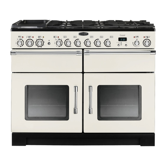
2. Cooker Overview DocNo.020-0002 - Overview - 90 Ceramic - Generic Fig.2-1 � � �� �� � � � ArtNo.190-0001 - 110 Ceramic annotated GENERIC � The 110 ceramic cooker (Fig.2-1) has the following features: Fig.2-2 A ceramic hob A control panel A separate grill or glide-out grill A programmable conventional or multi-function oven (depending on model) - Page 7 (Fig.2-7). Warmer (Rangemaster only) On the right of the hob is the Warmer (Fig.2-8). Use the warmer for keeping food warm while the final touches are put to a meal.
-
Page 8: The Grill / Glide-Out Grill
The Grill / Glide-out Grill Fig.2-10 Open the door and pull the grill pan (Fig.2-10) or carriage (Fig.2-11) forward using the handle. The grill has two elements that allow either the whole area of ArtNo.330-0003 - Grill pan w handle pulled forwards the pan to be heated or just the right-hand half. - Page 9 The browning element and base heat can be used in the You will also find that the food needs to be watched and latter part of the cooking process to fine tune the results to turned less than for normal grilling. Preheat this function your particular requirements.
-
Page 10: Operating The Ovens
Defrost with the oven door closed. Fig.2-14 Large items, such as whole chickens and joints should not be defrosted in this way. We recommend this be carried out in a refrigerator. Defrosting should not be carried out in a warm oven or when an adjoining oven is in use or still warm. -
Page 11: The Clock
The Clock ArtNo.300-0004 2-button clock annotated Fig.2-16 You can use the clock to turn the left-hand oven on and off. The clock must be set to the time of day before the oven will work. Note: When using the timer functions, first set the clock as required before setting the oven temperature and selecting the oven function (multi-function ovens only). - Page 12 Turn the Adjusting knob to set the ‘cooking time’ you need ArtNo.301-0010 2BC Fig.2-22 (Fig.2-22). Setting the cooking time Turn the Timer knob to the ( ) position. The display will show the current time of day plus the ‘cook time’ you just set. Use the Adjusting knob to set the ‘stop time’...
- Page 13 The 6-button Clock Fig.2-29 Setting the time of day The 6-button LCD clock is shown in Fig.2-29. When the clock is first connected the display flashes ( 0.00) and ( alternately. ArtNo.302-0002 - 6BC annotated Press and hold both the [] and [] buttons down (Fig.2-30).
- Page 14 AUTO is showing, you want to reset to manual cooking Fig.2-39 Fig.2-40 To return to manual cooking from any automatic setting, the ‘cook period’ must be cancelled. Press and hold the [] button and then press the [–] button until the display reads ( 0.00).
-
Page 15: Accessories
Accessories Fig.2-44 Oven Shelves – Left-hand (Main) Oven � In addition to the flat shelves (Fig.2-44), some models are supplied with a drop shelf (Fig.2-45). The drop shelf increases the possibilities for oven shelf spacing. The oven shelves can be easily removed and refitted. Pull the shelf forward until the back of the shelf is stopped by the shelf stop bumps in the oven sides (Fig.2-46). -
Page 16: Main Oven Light
Main Oven Light Fig.2-52 Press the button to turn the light on (Fig.2-52). If the oven light fails, turn off the power supply before ArtNo.320-0017 Main oven light changing the bulb. See the ‘Troubleshooting’ section for details on how to change the bulb. Storage The bottom drawer is for storing oven trays and other Fig.2-53... -
Page 17: Cooking Tips
DocNo.030-0002 - Cooking tips - electric 3. Cooking Tips Tips on Cooking with the Timer General Oven Tips If you want to cook more than one dish, choose dishes that The wire shelves should always be pushed firmly to the back require approximately the same cooking time. -
Page 18: Cooking Table
4. Cooking Table DocNo.031-0004 - Cooking table - electric & fan single cavity The oven control settings and cooking times given in the table below are intended to be used AS A GUIDE ONLY. Individual tastes may require the temperature to be altered to provide a preferred result. -
Page 19: Cleaning Your Cooker
Ceramic Hob Cleaner set with scraper. More information is available through either the Cookware Collection brochure supplied with your cooker or our website www.rangemaster.co.uk. Remember to switch the electricity supply back on and reset the clock before re-using the cooker. -
Page 20: Grills
Once you have removed as much as possible with the scraper, Fig.5-2 follow the ‘Daily Care’ procedure outlined above. To Remove Metal Rub-off Sliding pans on the hob – especially aluminium or copper pans – can leave marks on the surface. These marks often appear like scratches, but can easily be removed using the procedure described previously for ‘Cleaning Spills’. -
Page 21: Control Panel And Doors
Oven Doors with Glass Panels Fig.5-7 The oven door front panels can be taken off so that the glass panels can be cleaned. Move the cooker forward to gain access to the sides (see the ‘Moving the Cooker’ section under ‘Installation’). -
Page 22: Cleaning Table
Cleaning Table Cleaners listed are available from supermarkets or electrical retailers as stated. For enamelled surfaces use a cleaner that is approved for use on vitreous enamel. Regular cleaning is recommended. For easier cleaning, wipe up any spillages immediately. Hotplate Part Finish Recommended Cleaning Method... -
Page 23: Troubleshooting
DocNo.050-0002 - Troubleshooting - Ceramic Generic 6. Troubleshooting Power failure Interference with and repairs to the hob MUST NOT be carried out by unqualified persons. Do not try In the event of a failure in the electrical supply, to repair the hob as this may result in injury and remember to reset the clock to ensure that the timed damage to the hob. - Page 24 The Oven light is not working Fig.6-1 The bulb has probably blown. You can buy a replacement bulb (which is not covered under the guarantee) from most electrical stores. Ask for an Edison ArtNo.324-0005 Oven light bulb screw fitting 15W 240V lamp, FOR OVENS (Fig.6-1). It must be a special bulb, heat resistant to 300°C.
-
Page 25: Installation
INSTALLATION Check the appliance is electrically safe when you have finished. 7. Installation Dear Installer You will also need the following tools: Electric drill Before you start your installation, please complete the details below, so that, if your customer has a problem relating to Masonry drill bit (only required if fitting the cooker on a your installation, they will be able to contact you easily. -
Page 26: Positioning The Cooker
INSTALLATION Check the appliance is electrically safe when you have finished. ArtNo.090-0028 - 90 cooker min spacing GENERIC Positioning the Cooker Fig.7-1 Fig.7-1 shows the minimum recommended distance from the ���� ���� cooker to nearby surfaces. ��� ��� ����� ��� The cooker should not be placed on a base. -
Page 27: Completing The Move
INSTALLATION Check the appliance is electrically safe when you have finished. Removing the Storage Drawer Fig.7-6 Pull the drawer out to its furthest point (Fig.7-5). Lift up the ends of the plastic clips (one each side) to release the catches holding the drawer to the side runners and at the same time pull the drawer forward and away from the side runners (Fig.7-6). -
Page 28: Levelling
INSTALLATION Check the appliance is electrically safe when you have finished. Levelling Fig.7-10 It is recommended that you use a spirit level on a shelf in one of the ovens to check for level. Place the cooker in its intended position, taking care not to twist it within the gap between the kitchen units as damage may occur to the cooker or the units. -
Page 29: Electrical Connection
INSTALLATION Check the appliance is electrically safe when you have finished. Electrical Connection Fig.7-11 The cooker must be installed by a qualified electrician, in accordance with all relevant British Standards/Codes of � Practice (in particular BS 7671), or with the relevant national �... -
Page 30: Fitting The Plinth
INSTALLATION Check the appliance is electrically safe when you have finished. Fitting the Plinth Fig.7-16 Loosen the three screws along the front bottom edge of the cooker. Hook the central keyhole over the central screw. Twist and fit each end keyhole over their respective screws. Tighten the fixing screws (Fig.7-16). -
Page 31: Circuit Diagrams
8. Circuit Diagrams ArtNo.095-0003 - Circuit diagram - 90 induction Circuit Diagram: Hob (with warmer plate) �������������� �� �� �� � �� �� �� �� �� � � � � � � � � � � � � � � �... - Page 32 Circuit Diagram: Hob (Dual purpose hob/warmer plate) �������������� �� �� �� �� �� �� �� � � � � � � � � � � � � � � ������ ����� ������ ����� � ����� ������ bk/w � � � �...
- Page 33 Circuit Diagram: Hob (Classic Deluxe and Elan) �������������� �� �� �� �� �� �� �� � � � � � � � � � � � � � � ������ ����� ������ ����� � ����� ������ bk/w � � � �...
-
Page 34: Circuit Diagram: Conventional Oven
Circuit Diagram: Conventional Oven �� ������������� �� ������������� �������������� � ������ � �� � �� �� �� � � �� �� � � � � � � �� � �� � � � � � � � � � �� ��... -
Page 35: Circuit Diagram: Multi-Function Oven
Circuit Diagram: Multi-function Oven (Elan) �� �� � �� �� � � � �� � �� � � �� �� � �� � �� �������������� � �������������� �� �� � �� ��������������� �� �� � � � ������ �� � �... -
Page 36: Circuit Diagram: Multi-Function Oven
Circuit Diagram: Multi-function Oven (Classic Deluxe) To terminal P6 �� on the warmer � ��� �� hob controller � � �� switch � � � �� �� � �� � � �� �� �� �� �� � � � �� ��... -
Page 37: Technical Data
9. Technical Data ArtNo.100-0002 - Technical data - 90 ceramic - GENERIC INSTALLER: Please leave these instructions with the user. DATA BADGE LOCATION: Cooker back, serial number repeater badge below oven door opening. Connections Electric 220 - 240V 50Hz Dimensions Overall height minimum 905mm maximum 932mm... - Page 40 DocNo.000-0001 - Back cover Rangemaster �������������� ����������� ������� ����� w w w.ra n g e m a s t e r.c o .u k ArtNo.000-0003 CE logo...
Need help?
Do you have a question about the Toledo 110 Ceramic and is the answer not in the manual?
Questions and answers