Table of Contents
Advertisement
MULTI-ZONE
MIXER AMPLIFIERS
0
1
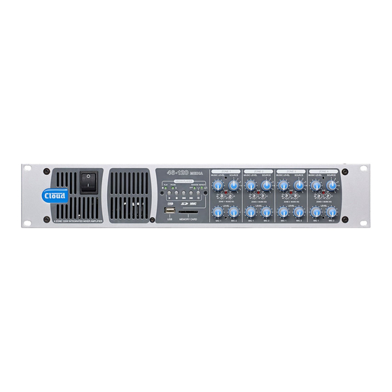
4 Z ONE 120W
INTEG RATED MIX ER AMPLIF IER
Installation and User Guide
46-120
46-120
MEDIA
46-120T
46-120T
MEDIA
46
-
120
Z ONE 1
MEDIA
MUSIC LEV EL
MEDIA PLAY ER
PLAY
PAUSE
RANDOM REPEAT
CLIP
LF
-
10
d B
0
10
10
Z ONE 1 MUSIC EQ
LEV EL
USB
MEMORY CARD
MIC 1
Z ONE 2
Z ONE 3
SOURCE
MUSIC LEV EL
SOURCE
MUSIC LEV EL
SOURCE
MUSIC LEV EL
1
1
1
2
2
2
3
3
3
4
4
4
5
5
5
CLIP
CLIP
H F
LF
H F
LF
H F
6
6
6
-
10
-
10
0
d B
0
0
d B
0
0
10
10
10
10
Z ONE 2 MUSIC EQ
Z ONE 3 MUSIC EQ
LEV EL
LEV EL
MIC 2
MIC 1
MIC 2
MIC 1
MIC 2
46-120 Installation and User Guide V1.1
Z ONE 4
SOURCE
1
2
3
4
5
CLIP
LF
H F
6
-
10
d B
0
0
10
10
Z ONE 4 MUSIC EQ
LEV EL
MIC 1
MIC 2
Advertisement
Table of Contents

Related Manuals for Cloud 46-120


Summary of Contents for Cloud 46-120
- Page 1 LEV EL MEMORY CARD MIC 1 MIC 2 MIC 1 MIC 2 MIC 1 MIC 2 MIC 1 MIC 2 4 Z ONE 120W INTEG RATED MIX ER AMPLIF IER Installation and User Guide 46-120 Installation and User Guide V1.1...
- Page 2 The exclamation point within an equilateral triangle is intended to alert the user to the presence of important operating and maintenance (servicing) instructions in the literature accompanying the appliance. 46-120 Installation and User Guide V1.1...
- Page 3 Class 2 Wiring, but voltages at these terminals may be of sufficient magnitude constitute a risk of electric shock. The external wiring connected to these terminals requires installation by an instructed person or the use of pre-made leads or cords. 46-120 Installation and User Guide V1.1...
-
Page 4: Table Of Contents
Speaker outputs ................................ 19 Auxiliary line outputs .............................. 20 Music Mute ................................. 20 Remote Power Down .............................. 20 SETTING UP & OPERATION ....................21 Music Inputs .................................. 21 Gain & level ................................21 Local/remote control ............................... 21 46-120 Installation and User Guide V1.1... - Page 5 Table of internal jumpers and default settings ....................31 PSU capability and optional device current consumption .................. 32 EMC considerations ..............................32 Ground loops ................................32 Technical specifications ....................... 33 General specifications ........................34 46-120 Installation and User Guide V1.1...
-
Page 6: Safety Information
Safety Considerations and SAFETY INFORMATION Information Safety Notes regarding Installation All versions of the Cloud 46-120 must be earthed. Ensure • Do not expose the unit to water or moisture. that the mains power supply provides an effective earth connection using a three-wire termination. -
Page 7: Overview
The Cloud 46-120 is an integrated, analogue audio mixer amplifier. It combines simple control of background music Unpack the 46-120 and its accessories with care. It is always a for four independent zones with versatile microphone paging good idea to store all packaging (if practical), in case you ever and power amplification in a single unit. -
Page 8: Key Features
Energy-saving auto power-down function, Ethernet- controllable (when CDI-46 is fitted) and a stereo line input in a remote location to be connected to the 46-120. The faceplate has both phonos and a 3.5 mm • Remote standby mode control by contact closure jack socket for connection of the line input, and provides a •... -
Page 9: Rl-1 Series
RSL-6 Series The Cloud PM1 paging microphone is also compatible with SOURCE SELECT the 46-120. It is a much simpler unit which addresses a single zone (though zones may be paralleled for wider access). See page 17 for more information. -
Page 10: Block Diagram
Block Diagram The simplified block diagram above illustrates the basic signal architecture of the 46-120. 46-120 Installation and User Guide V1.1... -
Page 11: Front Panel Description
Zone idents – a space is provided above each zone’s controls for printed labels identifying the zone by name. Fixing holes for security cover – prevents access to Zone EQ controls. The following front panel items are only fitted to the 46-120 and 46-120T... -
Page 12: Rear Panel Description
70 V-line on the 46-120T MEDIA and 46-120T models (as standard). If one or more CXL-46T transformers have been retrofitted to a 46-120 or MEDIA 46-120 , they may be either 100 V or 70 V-line. A checkbox area is provided below the connector for the installer MEDIA to indicate the configuration of each zone output. - Page 13 16. MUSIC MUTE – 2-pin 5 mm-pitch screw terminal connector for connection of external emergency muting relay (e.g., fire control panel). See page 20. 17. REMOTE POWER DOWN – 2-pin 5 mm-pitch screw-terminal connector allowing the 46-120 to be put into Standby Mode from external control systems. See page 20.
-
Page 14: Installation
Music sources of the unit by the fan. It is recommended that 1U blank panels are fitted in the rack above and below the 46-120; do not fit Connect the system’s various music sources to LINE 1 slotted ventilation panels as these defeat the action of forced- to LINE 6 as required. -
Page 15: Microphone Input
FACILITY PORT will only be available in pin 3 cold Zone 1, and no other. The active modules operate from DC power supplied by the 46-120. The current consumed by each module is minimal and 46-120 Installation and User Guide V1.1... -
Page 16: Paging System Connections
Screen for system music controls Connector shell Connecting PM4/4SA paging microphones Cloud PM Series microphones are available in 4, 8, 12 or 16- * Standard wiring for pre-made cables zone versions; the installer should be sure he/she understands how paging zones correspond to mixer zones before ... -
Page 17: Music Control
The diagram below shows the cable connections between a The following diagram shows the connections between a PM1 PM4 and a 46-120 and a 46-120. Use of 2-pair cable is assumed; the same wiring principle is adopted if separate cables are being used for audio and control. -
Page 18: Cdi-46 Digital Interface
The optional CDI-46 Digital Interface card may be retrofitted page. Either single-core screened or twin-and-screen cable to the 46-120 at any time. Full fitting instructions are supplied may be used; in the case of the latter, ignore one of the cores. -
Page 19: Speaker Outputs
Note that one pin of the line level output is connected 100/70 V line operation internally to 0 V. The 46-120 may be used with 100 V/70 V-line loudspeaker The transformer-isolated output is suitable for connection to systems by the use of Cloud CXL-46T transformers. These a nominal 600 ohm load. -
Page 20: Auxiliary Line Outputs
MUSIC MUTE high power levels than the 120 W available from the 46-120’s INPUT channels. To permit the connection of further amplifiers (or any other equipment), unbalanced outputs from the 46-120’s... -
Page 21: Setting Up & Operation
Sample rates supported are: 8 kHz, 11.025 kHz, 12 kHz, 46-120’s front panel or from a remote location, and should be 16 kHz, 22.05 kHz, 24 kHz, 32 kHz, 44.1 kHz and 48 kHz... -
Page 22: Basic Operation
Stop Mode; the next track played when H is pressed will then repeat until Repeat Mode is cancelled. The MIC 1/TEL input on the 46-120 may be reconfigured to accept an audio input directly from a compatible telephone... -
Page 23: Zone And Moh/Utility Outputs
The MOH/UTILITY MIC 1 LEVEL control installed. The 46-120 is fitted with per-zone HF and LF EQ should be turned fully down if the output is to be adjustments for the music signal ([5] on page 11) to enable... -
Page 24: Priorities
Examples of some basic commands are given below: over the time constant selected by J15 (3, 6 or 12 s). Note that on the 46-120, Line 6 Priority is only effective in COMMAND ASCII NOTES Zone 1. -
Page 25: Auto Power Down
As well as the browser control from the GUI, serial commands J18A is the MSB, J18C the LSB. The table below summarises may be sent to the 46-120 via the CDI-46 card in TCP/IP the required settings for each idle time value. -
Page 26: Options And Additional Information
If multiple LM-2s are “daisy-chained”, only one may have its music controls operative; see the LM-2 Installation Guide for considerations full details. Cloud LM-2 remote input modules are available in three Using the Facility Port as an auxiliary form factors, to fit double-gang UK, American or German zone input DIN-standard electrical back boxes. -
Page 27: Fitting The Cdi-46 Digital Interface
(0 V) of the equipment supplying the control in their required positions before fitting this card. voltages. To minimise this risk, we suggest that all pieces of Disconnect the 46-120 from the AC mains. equipment be in close proximity, and supplied from the same power outlet. -
Page 28: Fitting Loudspeaker Eq Cards
Mount the CXL-46T transformer(s) on the right-hand two notches on one side only; these engage with lugs on the side of the 46-120 chassis, using the holes in the side of equalisation module’s mating connector to ensure correct the chassis and the M5 x 40 screw, washer and locknut orientation. -
Page 29: Bypassing Transformers In The 46-120T And 46-120T Media
Fitting the EQ security cover A security cover is supplied with the 46-120 which can be The panel is simply placed over the rotary control knobs fitted to the front panel to prevent access to the Zone EQ and secured in place with the four M3 x 6 hex-head screws preset controls. -
Page 30: Appendix
Most jumpers have two possible positions; the black square in the symbol indicates the default setting. If any jumpers need to be changed, turn the 46-120 off and disconnect it from the mains. Undo the 10 screws securing the top cover of the unit and remove it. -
Page 31: Table Of Internal Jumpers And Default Settings
Binary weighting applies: see table at page 25. disabled) 1. On models 46-120T and 46-120T , default setting is ON. MEDIA 2. Operative on Models 46-120 and 46-120T only. MEDIA MEDIA 3. All jumpers in the set must be moved together. 46-120 Installation and User Guide V1.1... -
Page 32: Psu Capability And Optional Device Current Consumption
PSU capability and optional device EMC considerations current consumption The Cloud 46-120 fully conforms to the relevant electromagnetic compatibility (EMC) standards In addition to supplying the Mixer Amplifier’s circuitry, the is technically well behaved; you should experience no internal PSU has the capacity to power some additional items operational problems and under normal circumstances, no which may form part of a complete system. -
Page 33: Technical Specifications
100V balanced – 83 ohm min. load 100/70 V-line output* Frequency response -3 dB @ 65 Hz (filter), -2.5 dB @ 20 kHz Distortion <0.06% @ 1 kHz, 80 kHz bandwidth *with optional CXL-46T transformer(s) 46-120 Installation and User Guide V1.1... -
Page 34: General Specifications
23.5 in x 6.2 in x 21.3 in 46-120/46-120 : 11.75 kg (26.32 lbs) MEDIA 46-120T/46-120T : 15.75 kg (35.28 lbs) MEDIA Weight 46-120/46-120 : 13.95 kg (31.25 lbs) MEDIA Shipping 46-120T/46-120T : 17.95 kg (40.21 lbs) MEDIA 46-120 Installation and User Guide V1.1... - Page 35 46-120 Installation and User Guide V1.1...
- Page 36 Cloud Electronics Limited Cloud Electronics USA 140 Staniforth Road 1200 Iron Horse Drive, Unit A Sheffield S9 3HF Park City England Utah 84060. Tel: +44 (0)114 244 7051 United States of America. Fax: +44 (0)114 242 5462 Toll Free: 0855 810 0161 email: info@cloud.co.uk...
Need help?
Do you have a question about the 46-120 and is the answer not in the manual?
Questions and answers