Table of Contents
Advertisement
Quick Links
Advertisement
Table of Contents

Subscribe to Our Youtube Channel
Summary of Contents for Cloud 44
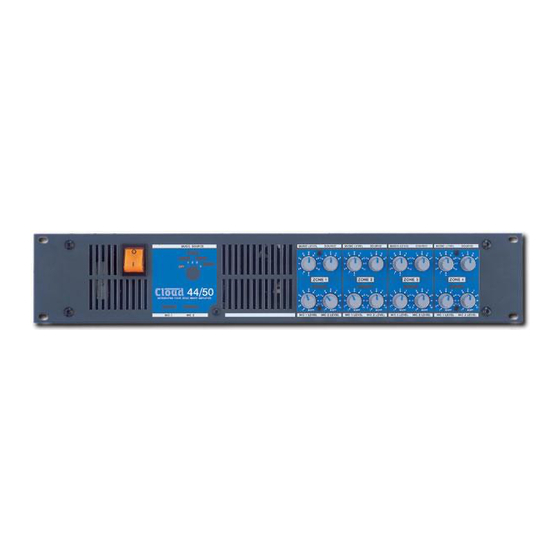
- Page 1 44/50 4 Zone Integrated Mixer Amplifier Installation & Operation Manual Cloud Electronics Limited 140 Staniforth Road, Sheffield, S9 3HF England Tel + 44 (0) 114 244 7051 Fax + 44 (0) 114 242 5462 E-mail info@cloud.co.uk Web site http://www.cloud.co.uk...
-
Page 2: Table Of Contents
Music equalisation ................3 Line 4 priority ..................4 Microphone inputs ................4 Paging microphone................4 Connecting Multiple CPM-4s to the 44/50 .......... 4 Microphone gain control..............5 Microphone equalisation ..............5 High pass filter ................... 6 Microphone level controls ..............6 Microphone priority ................ -
Page 3: Safety Notes
The Cloud 44/50 is supplied with a power cable fitted with a moulded plug; if the plug is cut off the lead for any reason, remember that the discarded plug is a potential hazard and should be disposed of in a responsible manner. -
Page 4: Installation
375mm should be allowed to clear connectors. Music Inputs The 44/50 operates in mono but is fitted with four stereo line inputs, which are internally mixed to form a mono signal. The line inputs are suitable for most music sources such as compact disc players, tape players and receivers etc. -
Page 5: Line 4 Priority
• A Sub D-type male connector • 4 M16 Nuts NOTE: Should you wish to order a CPM-8 for use with the 44/50 then you must also order a 44/50 paging mic installation kit as it does not come as standard. -
Page 6: Connecting Multiple Cpm-4S To The 44/50
44/50: Installation and Operation Manual We suggest that the CPM-4 should be wired using 2-core screened cable directly to the MIC 1 XLR input and 6-core cable with overall screen to the 44/50 paging microphone connector (as shown below). As an alternative the CPM-4 can connect to the MIC 1 input stage via the 9 pin ‘D’... -
Page 7: High Pass Filter
The CXL-400 four-channel line transformer module is available as an accessory to the 44/50. It is rated at 40 watts per channel and optimally matches the Cloud 44/50 power amplifiers. The module is designed to fit inside the 44/50 chassis and may be configured... -
Page 8: Remote Music Mute - Fire Alarm Interface
3. Remove the blanking plate from the rear panel 4. To the right of the large heat sink (looking at the 44/50 from the front panel) you will see three M3 fixing screws each next to a white arrow marked on the PCB, remove and retain these screws then fix three 35mm hex spacers in their place. -
Page 9: Music Signal Processing Pcb
When the RL-1 is used with the 44/50, wire it with single-core screened cable. It is assumed that the front panel music source select control will operate normally and the jumpers J1, J2, J3 &... -
Page 10: Controlling Two Or More Zones With One Rsl-1
44/50: Installation and Operation Manual RL-1 Wired to Operate Two Zones Controlling two or more zones with one RSL-1 A single RSL-1 can be used to control more than one zone; however, the three resistors fitted to the RSL-1 will have to be replaced with a different value. Where a single RSL-1 is used to control two zones, the resistors R1, R2 &... -
Page 11: Controlling The Music Functions Using External Dc Control
0-10V DC voltage. The 3-pole connector normally used to terminate the RSL-1 control plate can be used to feed two separate control voltages into the 44/50. Pin 1 is a ground (0V) termination common to both control voltages; this should be connected to the technical ground (0V) of the voltage source. -
Page 12: Technical Specifications
44/50: Installation and Operation Manual Technical Specifications Line inputs 20Hz-20kHz ±0.5dB Frequency Response Distortion <0.05% 20Hz -20kHz Sensitivity 195mV (-12dBu) to 2.0V (+8dBu) Input Gain Control 20dB range Input Impedance 47kΩ Headroom >20dB Noise -90dB A weighted (0dB gain) HF: ±10dB/10kHz LF: ±10dB/50Hz... -
Page 13: Safety Considerations
44/50: Installation and Operation Manual This product conforms to the following European Standards EN 50081-1:1992 EN 50082-1:1992 EN 60065:1994 Safety Considerations THIS UNIT MUST BE EARTHED. ENSURE THAT THE MAINS POWER SUPPLY PROVIDES AN EFFECTIVE EARTH CONNECTION USING A THREE WIRE TERMINATION.


Need help?
Do you have a question about the 44 and is the answer not in the manual?
Questions and answers