Table of Contents
Advertisement
Quick Links
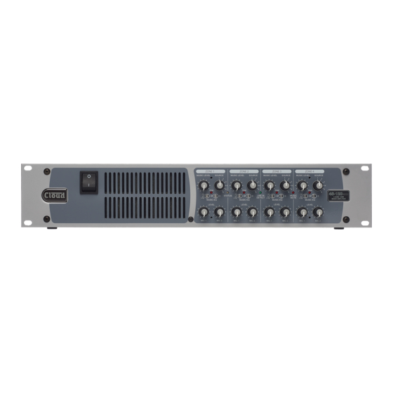
FOUR ZONE MIXER-AMPLIFIERS
Installation and User Guide
46 SERIES
ZONE 1
1
2
3
4
5
PEAK
6
-10
STATUS
HF
0
LF
+10
MUSIC EQ
LEVEL
MIC 1
MIC 2
ZONE 1
1
2
3
4
5
PEAK
6
-10
HF
0
STATUS
LF
+10
MUSIC EQ
LEVEL
MIC 1
MIC 2
ZONE 2
ZONE 3
ZONE 4
1
1
2
2
3
3
4
4
5
5
PEAK
PEAK
PEAK
6
6
-10
-10
-10
LINE IN
MUSIC
HF
0
HF
0
HF
LF
LF
LF
DETECT
MUTE
+10
+10
+10
MUSIC EQ
MUSIC EQ
MUSIC EQ
LEVEL
LEVEL
LEVEL
MIC 1
MIC 2
MIC 1
MIC 2
MIC 1
ZONE 2
ZONE 3
ZONE 4
1
1
2
2
3
3
4
4
5
5
PEAK
PEAK
PEAK
6
6
-10
-10
-10
LINE IN
MUSIC
HF
0
HF
0
HF
LF
LF
LF
DETECT
MUTE
+10
+10
+10
MUSIC EQ
MUSIC EQ
MUSIC EQ
LEVEL
LEVEL
LEVEL
MIC 1
MIC 2
MIC 1
MIC 2
MIC 1
46 Series Installation and User Guide V1.0
1
2
3
4
5
6
0
4 ZONE 120W
MIXER AMPLIFIER
MIC 2
1
2
3
4
5
6
0
4 ZONE 240W
MIXER AMPLIFIER
MIC 2
Advertisement
Table of Contents

Related Manuals for Cloud 46 Series


Summary of Contents for Cloud 46 Series
- Page 1 MIXER AMPLIFIER MUSIC EQ MUSIC EQ MUSIC EQ MUSIC EQ LEVEL LEVEL LEVEL LEVEL MIC 1 MIC 2 MIC 1 MIC 2 MIC 1 MIC 2 MIC 1 MIC 2 Installation and User Guide 46 Series Installation and User Guide V1.0...
- Page 2 The exclamation point within an equilateral triangle is intended to alert the user to the presence of important operating and maintenance (servicing) instructions in the literature accompanying the appliance. 46 Series Installation and User Guide V1.0...
- Page 3 Class 2 Wiring, but voltages at these terminals may be of sufficient magnitude to constitute a risk of electric shock. The external wiring connected to these terminals requires installation by an instructed person or the use of pre-made leads or cords. 46 Series Installation and User Guide V1.0...
-
Page 4: Table Of Contents
Microphone level controls ............................15 Microphone Equalisation .............................15 Paging control and mic priority ............................16 Microphone Access Input ..............................16 Connecting a PM4/4SA paging mic via the Cloud Digital Paging Interface ..........16 Connecting a paging mic via the analogue interface ...................17 Outputs ..................................18 Speaker Outputs ................................18 Connecting to Lo-Z loudspeakers ..........................18... - Page 5 46 SERIES SERIAL CONTROL..........................25 Abridged command set ..............................25 Examples ....................................26 APPENDIX ................................27 PCB jumper locations .................................27 Table of internal jumpers and default settings ......................28 Troubleshooting ..................................30 EMC Considerations ................................30 Earthing ....................................30 TECHNICAL SPECIFICATIONS ..........................31 46 Series Installation and User Guide V1.0...
-
Page 6: Safety Information
BS EN 55032:2015 (Emissions) BS EN 61000-3-2:2014 (Harmonics) Caution – Mains Fuse Cloud 46 Series mixer-amplifiers contain no user-replaceable fuses. Mains over-current protection is provided by the fuse in the IEC receptacle: only replace this fuse with one of an This product has been tested for use in commercial and light identical type and rating. -
Page 7: Overview
(4 x 120 or 4 x 240 watts). Otherwise the connection for each zone models have almost identical facilities. • CDPM Digital Paging port, for use with Cloud PM Series The mixer-amplifiers have inputs for six stereo line signals and two microphone signals. Front panel controls are provided... -
Page 8: What's In The Box
• LM-2 remote active mic/line input module with music Please check the shipping carton for damage before opening. source selection and volume controls If there is damage, please contact your Cloud agent and the shippers. • BT-1 remote Bluetooth wireless audio input module The packing carton should contain the following items: •... -
Page 9: Schematic Diagram
MIC1 AUDIO MIC 1 SOURCE MIC PRIORITY LEVEL ON / OFF LEVEL NORM. CLOSED / NORM. OPEN UTILITY RL-1 / RSL-6 MUSIC MUTE UTIL MIC AVO MIC2 AUDIO PRIORITY MUTE UTILITY MIC 2 LEVEL 46 Series Installation and User Guide V1.0... -
Page 10: Front Panel Description
LINE IN DETECT – green LED; illuminates when an input signal is detected at any of the line inputs. 10. Forced air cooling intake slots – do not block. 11. Mains power switch NOTE: Front panel items are referred to throughout this manual by numbers shown thus: 46 Series Installation and User Guide V1.0... -
Page 11: Rear Panel Description
Enables mic-over-music priority in Zone 4 Z4 MIC PRI. 20. CDPM INTERFACE – RJ45 socket for connection of Cloud PM4/8/12/16 digital paging microphones. 21. GAIN – Input level control for CDPM mic. 22. FACILITY PORT 1 and 2 – RJ45 sockets for connection of remote active input/control modules such as the LM-2, BT-1, L-1 and M-1. - Page 12 32. IEC mains input. 33. Mains fuse. 34. Forced air cooling exhaust slots – do not block. NOTE: Rear panel items are referred to throughout this manual by numbers in square brackets thus: 46 Series Installation and User Guide V1.0...
-
Page 13: Installation
“universal” type, and will operate on all AC mains supplies of between 85 V and 265 V, 45 to 65 Hz. An IEC mains cable The 46 Series mixer-amplifier is built in a 2U-high 19” rack with a plug appropriate for each country is supplied with the mount enclosure. -
Page 14: Connections And Controls
Remote Control of Music Source and Level standard phono sockets (RCA jacks) in pairs. LINE 3 to 46 Series mixer-amplifiers are compatible with standard LINE 6 are balanced, and use pairs of 3-pin 3.5 mm-pitch Cloud remote control plates: RSL-6 Series (music source screw terminal connectors. -
Page 15: Music Equalisation
The two preset MIC EQ controls are on the rear panel when reconfigured for paging, it operates as a standard Cloud- adjacent to the mic input; the LF and HF controls provide type paging input, with selectable mic-over-music priority ±10 dB of adjustment below 100 Hz and above 5 kHz... -
Page 16: Paging Control And Mic Priority
In the ON position (switch down), it operates as a typical external PSU, as described in the PM Series Installation Guide. Cloud paging input (PAGE mode). In this mode, pins on the (A suitable PSU is supplied as standard with all ‘-SA’ models.) -
Page 17: Connecting A Paging Mic Via The Analogue Interface
PM Series Installation and User Guide. The diagram below shows both the cable connections between a PM4 and a 46 Series unit. Note that the DC power supply connection will not be required if the PM microphone is powered independently by a local PSU. -
Page 18: Outputs
8 ohm Each zone of a 46 Series mixer-amplifier has both a low loudspeaker impedance output (4 or 8 ohms) and a high voltage output for 70/100 V-line speaker systems. Both output types are... -
Page 19: Power Sharing (Model 46-120Mk2 Only)
Parallel power stage operation Model 46-120MK2 incorporates the principle of Power 46 Series mixer-amplifiers may be configured so that one Sharing when the outputs of Zones 1 and 3 and/or Zones 2 zone signal (mix of music and mics) is routed to two output and 4 are configured for Hi-Z mode (i.e., for 70/100 V-line... -
Page 20: Auxiliary Outputs
Utility Output 46 Series mixer-amplifiers are provided with two assignable 46 Series mixer-amplifiers also have a Utility output, which auxiliary outputs: these are available on the AUX 1 and is ideal for providing the feed to a loop amplifier, or for AUX 2 connectors . -
Page 21: Facility Ports
RSL-6 or RL-1 remote controls. * Standard wiring for pre-made cables The various optional Cloud remote active modules operate from DC power supplied by the 46 Series mixer-amplifier. The current consumed by each module is minimal and in the ... -
Page 22: Connecting An Active Remote Module
LM-2 mic/line input module, with music source the same Facility Port. and level controls NOTE: 46 Series units are only compatible with the BT-1F variant of the BT-1: do not attempt to connect variant BT-1E). L-1/M-1: The L-1 and M-1 are remote active input modules... -
Page 23: Music Mute (Fire Alarm Interface)
Auto Power Down In some installations (such as licensed premises or retail A Cloud 46 Series mixer-amplifier is extremely energy- outlets within a shopping mall), there may be a local authority efficient, but can be made even more so by enabling the or fire service requirement to mute the music signals from a Auto Power-Down feature. -
Page 24: Options And Additional Information
Music source for a zone may be controlled by applying various DC voltages of between 0 and +3.3 V to pin 3, the 0 V reference being connected to pin 1. A voltage of between 46 Series Installation and User Guide V1.0... -
Page 25: 46 Series Serial Control
Ethernet port and a bi-directional RS-232 serial interface, amplifier from an AV control system. For all other commands, which permit remote control of numerous mixer-amplifier data requests and responses, please refer to the 46 Series’ full functions using serial commands. serial protocol document. -
Page 26: Examples
3. Mute/Unmute Mics The 46 Series mixer-amplifier’s mic inputs may be individually enabled or disabled. This may be done on a per-zone basis or globally (all zones). Note the character following ‘M’ may take the values ‘1’ (Mic 1), ‘2’ (Mic 2) or ‘I’ (both mics). -
Page 27: Appendix
PCB jumper locations 46 Series mixer-amplifiers have various internal jumpers, the setting of which may require alteration during installation. The diagram below (not to scale) shows the locations of the internal jumpers, all of which except J3, J15 and J16 are located on the sub board mounted above the lower main PCB. -
Page 28: Table Of Internal Jumpers And Default Settings
LEVEL control for Zone 1 or 3 (as selected by J19) Aux 1 level TRACK FIXED: Aux output 1 source is derived pre the front panel MUSIC LEVEL control for Zone 1 or Zone 3 (as selected by J19) 46 Series Installation and User Guide V1.0... - Page 29 Z1: Speaker Output 3 will be fed by the pre-amplifier for Zone 1 Z4: Speaker Output 4 will be fed by the pre-amplifier for Zone 4 Speaker 4 Routing Z2: Speaker Output 4 will be fed by the pre-amplifier for Zone 2 46 Series Installation and User Guide V1.0...
-
Page 30: Troubleshooting
Troubleshooting EMC Considerations Fault conditions are indicated by the front panel STATUS LED Cloud Series 46 mixer-amplifiers fully conform to the flashing either red or green. relevant electromagnetic compatibility (EMC) standards and are technically well behaved. You should experience no... -
Page 31: Technical Specifications
5 x 20 mm, time delay, T8A 0 °C to 35 °C (Note: performance and specifications cannot be guaranteed Normal operating temperature outside of this range) Cooling Forced air cooling (front to back) 46 Series Installation and User Guide V1.0... - Page 32 . Power: constant sound level at one-eighth maximum rated output (audio mainly clean, only occasional clipping) . Power: constant sound level at one-third maximum rated output (audio beginning to become compressed, limited or heavily clipped) 46 Series Installation and User Guide V1.0...
- Page 33 www.cloud.co.uk...
Need help?
Do you have a question about the 46 Series and is the answer not in the manual?
Questions and answers