Table of Contents
Advertisement
Quick Links
Download this manual
See also:
Manual
Advertisement
Table of Contents

Related Manuals for Cloud CX-A850


Summary of Contents for Cloud CX-A850
- Page 1 CX-A850 Amplifier Installation & User Guide V 4.0 Cloud Electronics Limited 140 Staniforth Road, Sheffield, S9 3HF England Tel +44 (0) 114 244 7051 Fax +44 (0) 114 242 5462 E-Mail: info@cloud.co.uk Web site: http://www.cloud.co.uk...
-
Page 3: Table Of Contents
CX-A850: Installation and Operation Manual CX-A850 Amplifier Installation and operation manual Contents Section Page Safety Notes ................2 General Description ..............2 Installation.................. 2 Input Facilities ................2 Input Routing Schematics ............3 Output Details ................4 100V Line operation ..............4 Bridged Mode Operation ............ -
Page 4: Safety Notes
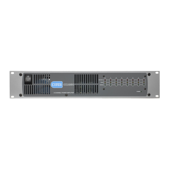
For more detailed information refer to the rear of the manual. General The CX-A850 is an eight-channel power amplifier with a typical output of 50 watts per channel into a 4Ω load. The unit features extremely low distortion and low noise together with a high slew rate. -
Page 5: Input Routing Schematics
CX-A850: Installation and Operation Manual 5 Input Routing Diagrams 8 independent mono amplifiers Fig 1 8 mono outputs fed from 1 mono input Fig 2 4 stereo amplifier pairs fed from 1 stereo input pair Fig 3 08-03-05 V4... -
Page 6: Output Details
CX-A850: Installation and Operation Manual Output Details Eight 2-pole plug-in screw terminal type connectors (5mm pitch) are provided on the rear panel for the eight speaker outputs; these can accommodate flexible leads up to 2.50mm². Do not make any connections to the unit with the power cable attached. It is good practice to distance the output wiring from the input wiring and keep the speaker wires twisted until they are terminated to reduce any cross-talk to a minimum level. -
Page 7: Status Indicators
"first channel" output and the negative wire is connected to the "second channel" output (see fig 5). Status Indicators The front panel of the CX-A850 has an array of LED’s that indicate the status of all eight channels (see Fig 6). Fig 6 The lower green ‘signal’... -
Page 8: Remote Level Plate Connections
25mm deep back box. Fig 11 As Fig 11 shows, the RL-1 is to be connected to a CX-A850 remote connector with a two- core cable that has an overall screen. It is possible to connect a single remote control module to control more than one channel simultaneously (Fig 11 right). -
Page 9: Equalisation Module Installation
7. Replace the top panel. NOTE: Before installing active modules, check section 10 for details of the power supply on the CX-A850. Each channel of the CX-A850 can have both a VCA-5 module and a speaker EQ card installed at the same time. -
Page 10: Technical Specifications
CX-A850: Installation and Operation Manual Technical Specifications Number of Channels Driven Rated Output 4 Ohm load(s) Rated Output 8 Ohm load(s) Bridged Output 100W nominal into 8 Ohm load, minimum load 8 Ohms Frequency Response +0dB –0.5dB 10Hz to 20kHz, switchable high pass filter –3dB... -
Page 11: Safety Considerations And Information
Only reassemble the unit using bolts/screws identical to the original parts Bose is a registered trademark of The Bose Corporation In the interest of continuing improvements Cloud Electronics Limited reserves the right to alter specifications without prior notice. Cloud Electronics Limited 140 Staniforth Road Sheffield S9 3HF England Telephone +44 (0) 114 244 7051 Fax +44 (0) 114 242 5462 E-mail: Info@cloud.co.uk...
Need help?
Do you have a question about the CX-A850 and is the answer not in the manual?
Questions and answers