Table of Contents
Advertisement
Quick Links
VTX SERIES
POWER AMPLIFIERS
VTX 4120, VTX 4240, VTX 4400
O
I
O
I
O
I
Installation and User Guide
CHANNEL
1
2
3
4
PROTECT
PEAK
SIGNAL
POWER
VTX 4120
4x 120W Amplifier
CHANNEL
1
2
3
4
PROTECT
PEAK
SIGNAL
POWER
VTX 4240
4x 240W Amplifier
CHANNEL
1
2
3
4
PROTECT
PEAK
SIGNAL
POWER
VTX 4400
4x 400W Amplifier
Advertisement
Table of Contents

Related Manuals for Cloud VTX 4120


Summary of Contents for Cloud VTX 4120
-
Page 1: Power Amplifiers
VTX SERIES POWER AMPLIFIERS VTX 4120, VTX 4240, VTX 4400 CHANNEL PROTECT PEAK SIGNAL POWER VTX 4120 4x 120W Amplifier CHANNEL PROTECT PEAK SIGNAL POWER VTX 4240 4x 240W Amplifier CHANNEL PROTECT PEAK SIGNAL POWER VTX 4400 4x 400W Amplifier... -
Page 2: Important Safety Instructions
WARNING: To reduce the risk of fire or electric shock, do not expose this appliance to rain of moisture CAUTION: Use of controls or adjustments or performance of prodedures other than those specified may result in hazardous radiation exposure. CAUTION RISK OF ELECTRIC SHOCK DO NOT OPEN WARNING: SHOCK HAZARD - DO NOT OPEN... -
Page 3: Table Of Contents
Contents Safety Information ........4 Safety Notes regarding Installation ......4 Safety Considerations and Information ....4 General Description ........5 VTX range main features ......... 5 Applicable Models ............5 Block Diagram ..........5 Front Panel Description ....... 6 Rear Panel Description ......... -
Page 4: Safety Information
Safety Information Caution - High Voltages Do not touch any part or terminal carrying the hazardous live symbol ( ) while power is supplied to the unit. Safety Notes regarding Installation • Do not expose the unit to water or moisture. Terminals to which the hazardous live symbol refers require installation by a qualified person. -
Page 5: General Description
General Description VTX range main features: • High power multichannel amplifiers for “install-and- Cloud VTX amplifiers are a range of high power multi- forget” applications channel audio amplifiers intended for use with high quality PA and music systems in locations where unquestionable •... -
Page 6: Front Panel Description
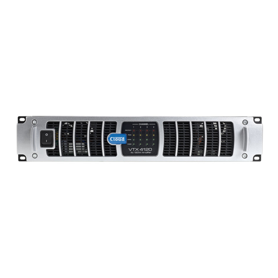
fig.2: VTX Front Panel (NOTE: VTX4120 shown – other models are identical) Front Panel Description POWER LEDs - (one per channel) – illuminate after PROTECT LEDs – (one per channel) – illuminate if power-up sequence to confirm normal power supply the internal heatsink temperature exceeds 90 °C operation AC Power switch... -
Page 7: Installation
Installation Connections and adjustments Inputs Mechanical Each amplifier channel has an electronically-balanced input on VTX amplifiers are designed to be mounted in a standard a 3-pin, 3.5 mm-pitch screw terminal connector. The mating 19” equipment rack. The front panel is fitted with rackmount connector is supplied. - Page 8 The three switches on the rear of VTX amplifiers allow a total of 8 routing possibilities, including 4-channel, dual stereo and mono operation with 4 channels paralleled. The table below clarifies the options: INPUT ROUTING: BUTTON POSITION AMPLIFIER AMPLIFIER CHANNELS FED BY EACH INPUT CONFIGURATION CH 2 CH 3...
-
Page 9: Protection
Protection 100 V/70 V-line operation VTX amplifiers may be used to drive 100 V-line or 70 V-line The amplifiers include comprehensive protection circuitry speaker systems with the addition of appropriate external to prevent damage to loudspeakers, the output devices and transformers. -
Page 10: Bose® Equalisation Modules (Optional)
Bose® equalisation modules General Notes (optional) EMC Considerations Cloud VTX amplifiers fully conform to the relevant electromagnetic compatibility (EMC) standards and are VTX amplifiers are compatible with Bose® Series II technically well behaved. You should experience no problems loudspeakers; a single-channel Bose® equalisation module interfacing units to other items of equipment and under may be fitted to as many channels as necessary. -
Page 11: Appendix
Appendix Technical Specifications VTX4120 VTX4240 VTX4400 Output (Normal Mode) 120 W (4Ω) 240 W (4Ω) 400 W (4Ω) Output (Bridged Mode) 240 W (8Ω) 480 W (8Ω) 800 W (8Ω) Frequency Response 20 kHz to 20 kHz, +0/-1 dB; (HPF bypassed) High Pass Filter -3 dB @ 65 Hz, slope 18 dB/octave (switchable) Distortion... -
Page 12: Location Of Jumpers And Other Internal Components
Location of jumpers and other internal components NOTE: The following jumpers and connectors are relevant to the optional VTX-WM1 surveillance card: J109 - J409 J110 - J410 J107 - 407A J801B, J802B Full details are in the VTX-WM1 Installation and User Manual BOSE®... -
Page 13: Factory Default Jumper Settings Table
Factory default jumper settings table Jumper/Connector Function Channel No. Default Setting J104 J204 Bose® EQ card sockets Empty J304 J404 J108 J208 Bose® EQ card bypass jumpers Present J308 J408 J107A J207A J307A J407A VTX-WM1 surveillance card interface sockets Empty J801B J802B J805B*... - Page 14 Bose® is a registered trademark of The Bose Corporation. In the interest of continuing improvements Cloud Electronics Limited reserves the right to alter specifications without prior notice. VTX Series User Manual v1.0...
- Page 16 Cloud Electronics Limited 140 Staniforth Road Sheffield S9 3HF England Tel: +44 (0)114 244 7051 Fax: +44 (0)114 242 5462 email: info@cloud.co.uk web: www.cloud.co.uk...
Need help?
Do you have a question about the VTX 4120 and is the answer not in the manual?
Questions and answers