Table of Contents
Advertisement
46-50 FOUR ZONE
INTEGRATED
MIXER AMPLIFIER
0
1
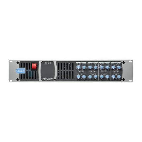
4 ZONE 50W INTEGRATED
MIXER AMPLIFIER
Installation and User Guide
ZONE 1
ZONE 2
ZONE 3
MUSIC LEVEL
SOURCE
MUSIC LEVEL
SOURCE
MUSIC LEVEL
1
1
2
2
3
3
4
4
5
5
CLIP
CLIP
CLIP
LF
HF
LF
HF
LF
6
6
-
10
-
10
-
10
dB
0
0
dB
0
0
dB
0
10
10
10
10
10
10
ZONE 1 MUSIC EQ
ZONE 2 MUSIC EQ
ZONE 2 MUSIC EQ
LEVEL
LEVEL
LEVEL
MIC 1
MIC 2
MIC 1
MIC 2
MIC 1
46-50 Installation and User Guide V1.0
ZONE 4
SOURCE
MUSIC LEVEL
SOURCE
1
1
2
2
3
3
4
4
5
5
CLIP
HF
LF
HF
6
6
-
10
0
dB
0
0
10
10
ZONE 2 MUSIC EQ
LEVEL
MIC 2
MIC 1
MIC 2
Advertisement
Table of Contents

Subscribe to Our Youtube Channel
Related Manuals for Cloud 46-50


Summary of Contents for Cloud 46-50
- Page 1 ZONE 2 MUSIC EQ LEVEL LEVEL LEVEL LEVEL 4 ZONE 50W INTEGRATED MIXER AMPLIFIER MIC 1 MIC 2 MIC 1 MIC 2 MIC 1 MIC 2 MIC 1 MIC 2 Installation and User Guide 46-50 Installation and User Guide V1.0...
- Page 2 The exclamation point within an equilateral triangle is intended to alert the user to the presence of important operating and maintenance (servicing) instructions in the literature accompanying the appliance. 46-50 Installation and User Guide V1.0...
-
Page 3: Important Safety Instructions
Class 2 Wiring, but voltages at these terminals may be of sufficient magnitude constitute a risk of electric shock. The external wiring connected to these terminals requires installation by an instructed person or the use of pre-made leads or cords. 46-50 Installation and User Guide V1.0... -
Page 4: Table Of Contents
Paging system connections ............................. 14 Music control ................................15 Zone 1 Facility Port ..............................16 Speaker outputs (Lo-Z) ............................16 Speaker outputs (100/70 V-line operation) ......................17 Auxiliary line outputs .............................. 17 Music Mute ................................. 17 46-50 Installation and User Guide V1.0... - Page 5 Fitting the EQ security cover ............................ 23 APPENDIX ........................... 24 PCB jumper locations ..............................24 Table of internal jumpers and default settings ....................25 EMC considerations ..............................26 Ground loops ................................26 TECHNICAL SPECIFICATIONS ....................26 GENERAL SPECIFICATIONS ....................27 46-50 Installation and User Guide V1.0...
-
Page 6: Safety Information
Safety Considerations and SAFETY INFORMATION Information Safety Notes regarding Installation The Cloud 46-50 must be earthed. Ensure that the mains • Do not expose the unit to water or moisture. power supply provides an effective earth connection using a three-wire termination. -
Page 7: Overview
Compatible with standard Cloud remote control plates: RL Series (music level) and RSL Series (music level and source selection), per-zone Unpack the 46-50 and its accessories with care. It is always a good idea to store all packaging (if practical), in case you ever •... -
Page 8: Optional System Components
- such as a DJ mixer, laptop, MP3 player or similar - to be connected to the 46-50 at a remote location. The module also includes the functions of the RSL-6 Remote... -
Page 9: Pm Series Microphones
The Cloud PM1 paging microphone is also compatible with Cloud PM Series paging microphones may be connected the 46-50. It is a much simpler unit which addresses a single directly to the 46-50 using MIC 1 input and the PAGING zone (although zones may be paralleled for wider access). -
Page 10: Block Diagram
Block Diagram The simplified block diagram above illustrates the basic signal architecture of the 46-50. 46-50 Installation and User Guide V1.0... -
Page 11: Front Panel Description
Power – rocker switch. Zone idents – a space is provided above each zone’s controls for printed labels identifying the zone by name. Fixing holes for security cover – prevents access to Zone EQ controls. 46-50 Installation and User Guide V1.0... -
Page 12: Rear Panel Description
14. MUSIC MUTE – 2-pin 5 mm-pitch screw terminal connector for connection of external emergency muting relay (e.g., fire control panel). See page 17. 15. Mains – IEC receptacle for AC mains. See page 13. 16. FUSE – mains fuse. See page 13 for fuse details. 46-50 Installation and User Guide V1.0... -
Page 13: Installation
The 46-50 Mixer Amplifier is built in a 2U-high 19” rack mount service centre. enclosure. It is recommended that the 46-50 is installed in a 19”... -
Page 14: Microphone Input
Installation and User Guide. Screen The diagram below shows the cable connections between a Signal ‘-‘ (cold) PM4 and a 46-50, where power is supplied by the 46-50. Signal ‘+’ (hot) PM4 PAGING MICROPHONE Unbalanced microphones may be used by connecting pin 2... -
Page 15: Music Control
The diagram below shows the connections between a PM1 via a DC voltage from third-party systems is also possible and a 46-50. Use of 2-pair cable is assumed; the same wiring (see page 21). principle is adopted if separate cables are being used for audio and control. -
Page 16: Zone 1 Facility Port
Cat 5 cable to a mating REMOTE SOURCE & LEVEL CONTROL WIRING male 9-pin Dsub connector in order to use it with the 46-50. This procedure, and details of how to configure the 46-50... -
Page 17: Speaker Outputs (100/70 V-Line Operation)
46-50’s of the 46-50 may be converted to 100 V and/or 70 V-line pre-amplifier sections for Zones 1 and 2 are available at the operation as required. -
Page 18: Setting Up & Operation
To avoid dramatic changes in volume when switching between a higher phantom voltage and thus necessitate an external sources, the 46-50’s music inputs are provided with preset PSU.) To enable phantom power at a mic input, internal gain trim controls ([2] on page 12). These vary the input motherboard jumpers J1 (MIC 1) and/or J2 (MIC 2) should sensitivity from -12 dBu (195 mV) to +8 dBu (2.0 V). -
Page 19: Zone Outputs
24 for locations of PCB jumpers. In some installations, a higher power output may be required in a zone than the 50 W the 46-50 power stages are rated at. To meet this requirement, the 46-50’s output stages may... -
Page 20: Line 6 Priority
If a remote active module is in use in Zone 1, it is possible to priority over all the others; for example, a jukebox in a bar, give a microphone connected at the 46-50 itself (at MIC 1 or or a digital sound store programmed to make automatic MIC 2) priority over input sources connected at the module. -
Page 21: Options And Additional Information
RL-1 and RSL-6 Series remote control plates – general considerations Cloud RL-1 Series and RSL-6 Series remote control plates are available in three form factors, two fit single-gang UK or American electrical back boxes respectively; the third is a 50 x 50 mm “Media” module, suitable for “Euro-module” mounting frames available in most European countries. -
Page 22: Using The Facility Port As An Auxiliary Zone Input
To install equalisation modules, first disconnect the permanently ‘force’ a zone to a particular line input. 46-50 from the AC mains supply, then remove the top cover (8 screws). The modules plug into the white 12-pin in-line sockets labelled CON3 (Zone 1), CON4 (Zone 2),... -
Page 23: Fitting The Eq Security Cover
Plug the 2-pin connectors on the other end of the flying lead assembly onto the corresponding headers on the A security cover is supplied with the 46-50 which can be fitted 46-50 main PCB (immediately behind the 100V/70V to the front panel to prevent access to the Zone EQ preset LINE OUTPUTS). -
Page 24: Appendix
Most jumpers have two possible positions; the black square in the symbol on the diagram below indicates the default setting. If any jumpers need to be changed, turn the 46-50 off and disconnect it from the mains. Undo the eight screws securing the top cover of the unit and remove it. -
Page 25: Table Of Internal Jumpers And Default Settings
3S: 3 seconds. release time Music Control Zone 1 Line 6 priority release time 6S: 6 seconds release time sub-board ABSENT: 12 seconds release time 1. These jumpers are factory-set to ON in Model 46-50T. 46-50 Installation and User Guide V1.0... -
Page 26: Emc Considerations
EMC considerations The Cloud 46-50 fully conforms to the relevant electromagnetic compatibility (EMC) standards and is technically well behaved; you should experience no operational problems and under normal circumstances, no special precautions need to be taken. If the unit is to be used within close proximity to potential sources of HF disturbance such as high power communications transmitters, radar stations and the like, the performance of the mixer may be reduced;... -
Page 27: General Specifications
610 mm x 200 mm x460 mm Shipping (Gross) 24” x 8” x 18” 7.65 kg /17 lbs (46-50); 10.5 kg / 23.1 lbs (46-50T) Weights Shipping (Gross) 10.2 kg / 23 lbs (46-50); 13.0 kg / 29.1 lbs (46-50T) 46-50 Installation and User Guide V1.0... - Page 28 Cloud Electronics Limited Cloud Electronics USA 140 Staniforth Road 1200 Iron Horse Drive, Sheffield S9 3HF Unit A, Park City, England Utah 84060. Tel: +44 (0)114 244 7051 United States of America. Fax: +44 (0)114 242 5462 Toll Free: 0855 810 0161 email: info@cloud.co.uk...
Need help?
Do you have a question about the 46-50 and is the answer not in the manual?
Questions and answers