Table of Contents
Advertisement
Quick Links
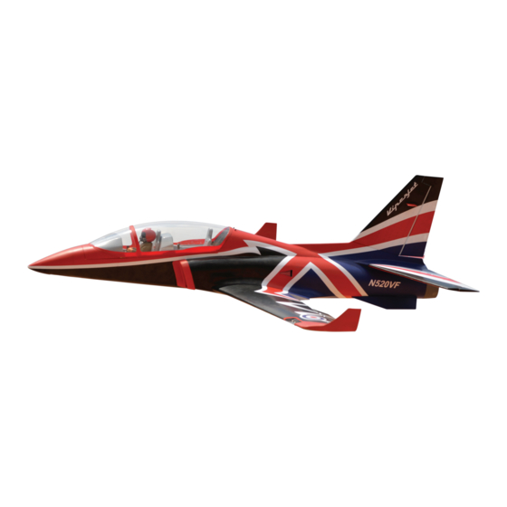
VIPER JET MKII
Glow and EP
ALL BALSA - PLY WOOD CONSTRUCTION
COVERED IN A HEAT-SHRINK FILM WITH PRINTED.
NOT INCLUDING ELECTRIC RETRACT GEAR
ONLY INCLUDING CNC SUSPENSION METAL STRUTS.
95% ALMOST READY TO FLY
SPECIFICATION:
- Wingspan: 1,885mm (74.21 in).
- Length: 1,820mm (71.65 in).
- Weight: 8.9 - 9.1kg (19.58 - 20 lbs).
- Wing area: 62.2dm
- Wing loading:143.1g/dm
- Wing type: Naca Airfoil.
- Gear type: Electric retract gear,
size: (92.55 x 51 x 35.1)mm (not included).
CNC Suspension Metal Struts (included).
Parts Listing required (not included):
- Radio: 8 channels minimum.
- Servo: 8 standard high torque servos, size: (33 x 17)mm.
- Engine: EDF 120mm.
- Battery: 10S - 12S LIPO 37V- 44.4 V.
- ESC: 160A.
Instruction Manual Book
.
2
.
2
Item code: BH175
Recommended EDF and Battery set up
(not included):
- Engine: Ducted Fan EDF JETFAN-120 eco
Ejets+ HET 800-68-685.
- Battery: 12S LIPO – 44.4 V ≥ 6000mAh 40C.
- Or Engine: Ducted Fan EDF Schubeler
DS-86-AXI HDS 120mm + TP 5660-9D motor.
- Battery: 10S LIPO - 37V ≥ 6000mAh 40C.
- ESC: 160A Phoenix Castle.
Made in Vietnam.
Advertisement
Table of Contents

Related Manuals for Black Horse Model BH175


Summary of Contents for Black Horse Model BH175
- Page 1 Instruction Manual Book Item code: BH175 VIPER JET MKII Glow and EP ALL BALSA - PLY WOOD CONSTRUCTION COVERED IN A HEAT-SHRINK FILM WITH PRINTED. NOT INCLUDING ELECTRIC RETRACT GEAR ONLY INCLUDING CNC SUSPENSION METAL STRUTS. 95% ALMOST READY TO FLY...
- Page 2 Thank you for purchasing Black Horse Model products. With over 18 years experience in production and fly testing, Black Horse Model is committed to bring the best quality products and good service to customers. Along with a team of creative engineers and skilled workers, we will always accompany with customers by our great experiences, fully enthusiasm...
- Page 3 In that Black Horse Model has no control over the final assembly or material used for final assembly, SUGGESTION Black Horse Model is not responsible for loss of use , or other incidental or consequential damages. To avoid scratching your new airplane, do not...
- Page 4 Viper Jet MKII Item code: BH175 Instruction Manual FLIGHT WARNINGS ADHESIVES AND REQUIRED TOOLS When ready to fly, first extend the transmitter aerial. Thin CA Switch on the transmitter. 30-minute epoxy Switch on the receiver. 6-minute epoxy Check that the wings are correctly fitted to the Threadlocker thread locking cement fuselage.
- Page 5 Viper Jet MKII Item code: BH175 Instruction Manual • Officially designated AMA Air Show Teams (AST) are authorized to use devices and practices as defined within the Team AMA Program Document. (AMA Document #718.) (j) Not operate a turbine-powered aircraft, unless in compliance with the AMA turbine regulations. (AMA Document #510-A.)
- Page 6 Viper Jet MKII Item code: BH175 Instruction Manual PARTS LISTING (NOT INCLUDED). EDF: 120mm Servo extension leads....pcs....1 pcs. 720mm ..3 pcs. 330mm ..2 pcs. LiPo: 4 Cell ....2 Packs 190mm ..8 pcs. LiPo: 6 Cell ....2 Packs Servos size: (32.3x16.8x31)mm.
- Page 7 Viper Jet MKII Item code: BH175 Instruction Manual : Fuselage. : Wing panel (2a, 2b). : Horizontal stabilizer (3a, 3b). : Vertical stabilizer. : Aluminium wing dihedral brace. : Aluminium tube horizontal stabilizer. : Aluminium tube vertical stabilizer. : Cockpit fuselage ( 8a: Canopy, 8b: Pilot, 8c: Cockpit).
- Page 8 Viper Jet MKII Item code: BH175 Instruction Manual INSTALLING THE AILERONS AND FLAPS Pinned hinge - - - - - - - - - - - - - 6 - - - - - - - - - - - - - 6...
- Page 9 Viper Jet MKII Item code: BH175 Instruction Manual Left wing Right wing INSTALLING THE AILERON AND FLAP SERVO Using the thread as a guide and using masking tape, tape the servo lead to the end of the thread: carefully pull the thread out. When you...
- Page 10 Viper Jet MKII Item code: BH175 Instruction Manual Flap Aileron Aileron and flap servos. 2 mm approx.16mm 2x10mm Screw For Flap. For Flap. 1.5 mm For Aileron. For Aileron. Screw 2 m m 1.5 mm 1.5 mm Set all scerws securely. If they come...
- Page 11 Viper Jet MKII Item code: BH175 Instruction Manual INSTALLING THE AILERON AND FLAP LINKAGES 4. Center the aileron and hold it in place using a 1. Install the control horn into the aileron and flap. couple of pieces of masking tape. Adjust the 2.
- Page 12 Viper Jet MKII Item code: BH175 Instruction Manual Apply threadlocker (screw cement). The number of times the same way Assembly (in this case twice). Assemble left and right sides the same way.
- Page 13 Viper Jet MKII Item code: BH175 Instruction Manual INSTALLING MAIN GEAR 43.70 30.70 92.20 24.10 21.00 48.50 ELECTRIC NOT INCLUDED. 5mm Washer 5x35mm Screw Screw 3x20mm Cap screw 3x4mm Setscrew - - - 8 - - - - - - - - - - - 2...
- Page 14 Viper Jet MKII Item code: BH175 Instruction Manual ELECTRIC GEAR RETRACTS Bottom view Bottom view Open Close Screw Cut off shaded portion carefully. Apply instant glue Must be purchased (C.A glue, super glue). separately! Assemble left and right C . A...
- Page 15 Viper Jet MKII Item code: BH175 Instruction Manual Apply threadlocker (screw cement). Assemble left and right sides the same way. Drill holes using the stated. (in this case 1.5mm 1.5mm Bottom view Bottom view 118mm 19mm...
- Page 16 Viper Jet MKII Item code: BH175 Instruction Manual Bottom view Bottom view Bottom view Assemble left and right sides the same way.
- Page 17 Viper Jet MKII Item code: BH175 Instruction Manual Top view Top view Wing tip Top view Apply epoxy glue. Must be purchased separately! Assemble left and right sides the same way.
- Page 18 Viper Jet MKII Item code: BH175 Instruction Manual Wing tip Top view INSTALLING HORIZONTAL STABILIZER Pinned hinge - - - - - - - - - - - - - 8 Bottom view Apply epoxy glue. Assemble left and right sides the same way.
- Page 19 Viper Jet MKII Item code: BH175 Instruction Manual Bottom view Assemble left and right sides the same way. INSTALLING THE HORIZONTAL STABILIZER SERVO Using the thread as a guide and using masking tape, tape the servo lead to the end of the thread: carefully pull the thread out.
- Page 20 Viper Jet MKII Item code: BH175 Instruction Manual Bottom view 2 mm approx.16mm 2x10mm Screw 1.5 mm Screw 2 m m 1.5 mm 1.5 mm Set all scerws securely. If they come 2 x 10mm Tp Screw Warning! off during flight you will lose control...
- Page 21 Viper Jet MKII Item code: BH175 Instruction Manual Set all scerws securely. If they come 2 x 10mm Tp Screw Warning! off during flight you will lose control - - - - 8 of your aircraft! 2x10mm Screw Bottom view <...
- Page 22 Viper Jet MKII Item code: BH175 Instruction Manual INSTALLING THE HORIZONTAL STABILIZER LINKAGES 1. Install the control horn into the horizontal stabilizer. 4. Center the horizontal stabilizer and hold it in place using a couple of pieces of masking tape. Adjust 2.
- Page 23 Viper Jet MKII Item code: BH175 Instruction Manual < Bottom view > Left < Bottom view > Right Apply threadlocker (screw cement). Assemble left and right sides the same way. The number of times the same way Assembly (in this case twice).
- Page 24 Viper Jet MKII Item code: BH175 Instruction Manual 12mm Aluminium tube. 312mm...
- Page 25 Viper Jet MKII Item code: BH175 Instruction Manual INSTALLATION THE VERTICAL STABILIZER Pinned hinge - - - - - - - - - - - - - 4 Hinges for Rudder are glued the same way as the aileron before.
- Page 26 Viper Jet MKII Item code: BH175 Instruction Manual Bottom view INSTALLATION THE VERTICAL STABILIZER SERVO Using the thread as a guide and using masking Install the rubber grommets and brass eyelets tape, tape the servo lead to the end of the onto the aileron servo.
- Page 27 Viper Jet MKII Item code: BH175 Instruction Manual 2 mm approx.16mm 2x10mm Screw 2 m m 1.5 mm Screw 1.5 mm 1.5 mm Set all scerws securely. If they come 2 x 10mm Screw Warning! off during flight you will lose control...
- Page 28 Viper Jet MKII Item code: BH175 Instruction Manual INSTALLATION THE VERTICAL STABILIZER LINKAGES 1. Install the control horn into the vertical stabilizer. 4. Center the aileron and hold it in place using a couple of pieces of masking tape. Adjust the 2.
- Page 29 Viper Jet MKII Item code: BH175 Instruction Manual Bottom view Apply threadlocker (screw cement).
- Page 30 Viper Jet MKII Item code: BH175 Instruction Manual 12mm Aluminium tube. 115mm Top view Top view...
- Page 31 Viper Jet MKII Item code: BH175 Instruction Manual Ply Wood part for rudder stab - - - - - - - - - 1 Top view Cut off shaded portion carefully. Apply instant glue (C.A glue, super glue). C . A...
- Page 32 Viper Jet MKII Item code: BH175 Instruction Manual INSTALLING THE NOSE GEAR RETRACT Metal Clevis - - - - - - - 2 Cable rod - - - - - - - 2 Locknut - - - - - - - 4...
- Page 33 Viper Jet MKII Item code: BH175 Instruction Manual Bottom view Bottom view 3x20mm Screw Bottom view Apply instant glue Drill holes using the stated. Cut off shaded portion (C.A glue, super glue). (in this case 1.5mm carefully. 1.5mm C . A...
- Page 34 Viper Jet MKII Item code: BH175 Instruction Manual 3x20mm Screw Bottom view Cable rod Crimp Cut off excess.
- Page 35 Viper Jet MKII Item code: BH175 Instruction Manual Bottom view Servo nose gear Metal Clevis Cab link Hex Nut Must be purchased Cut off excess. separately! Cut off shaded portion Pay close attention here. carefully.
- Page 36 Viper Jet MKII Item code: BH175 Instruction Manual Top view Connector Cable rod Servo nose gear...
- Page 37 Viper Jet MKII Item code: BH175 Instruction Manual INSTALLING THE EDF AND LIP OF AIR INLET, OUTLET Plastic air intake Fiberglass intake Right - - - - - - - - 2 Left Plastic air intake for cooling ESC - - - - - - - - 2...
- Page 38 Viper Jet MKII Item code: BH175 Instruction Manual Center Line Top view Cut off shaded portion carefully.
- Page 39 Viper Jet MKII Item code: BH175 Instruction Manual Top view Open / Close Hatch Bottom view...
- Page 40 Viper Jet MKII Item code: BH175 Instruction Manual 3x15mm Tp Screw - - - - - - - - - 4 3x15mm Tp Screw Foam Bottom view Foam Drill holes using the stated. Must be purchased separately! (in this case 1.5mm...
- Page 41 Viper Jet MKII Item code: BH175 Instruction Manual Adhesive tape. Bottom view Apply epoxy glue.
- Page 42 Viper Jet MKII Item code: BH175 Instruction Manual Bottom view Bottom view Ply Wood part for the rear bottom fuselage - - - - - - - - - - - 2 Bottom view Apply epoxy glue. Apply instant glue (C.A glue, super glue).
- Page 43 Viper Jet MKII Item code: BH175 Instruction Manual Bottom view Open / Close SECURE THE WING TO THE FUSELAGE 19mm Aluminium tube. Attach the wings to the fuselage and secure the 678mm wing panels. Bottom view...
- Page 44 Viper Jet MKII Item code: BH175 Instruction Manual Bottom view Assemble left and right sides the same way. Plastic air intake for cooling ESC - - - - - - - - - 2 Top view...
- Page 45 Viper Jet MKII Item code: BH175 Instruction Manual Top view INSTALLING THE SWITCH INSTALLING THE RECEIVER AND BATTERY 1. Plug the servo leads and the switch lead into the 1. The switch should be mounted on the fuselage receiver. You may want to plug an aileron...
- Page 46 Viper Jet MKII Item code: BH175 Instruction Manual Receiver Switch Battery Battery Top view Battery INSTALLING COCKPIT FUSELAGE Position the canopy so the rear frame on the canopy is aligned with the rear edge of the cockpit opening. Use canopy glue to secure the canopy to the canopy hatch.
- Page 47 Viper Jet MKII Item code: BH175 Instruction Manual Top view Top view Open/Close Top view Adhesive tape Apply epoxy glue.
- Page 48 Viper Jet MKII Item code: BH175 Instruction Manual BALANCING LATERAL BALANCE 1. It is critical that your airplane be balanced correctly. After you have balanced a plane on the C.G. Improper balance will cause your plane to lose You should laterally balance it. Doing this will control and crash.
- Page 49 Viper Jet MKII Item code: BH175 Instruction Manual In order to obtain the CG specified, reposition the receiver and other equipment. If not obtain the CG specified, add a weight and Do not fly before confirming the adjust. correct location of the CG. If the...
- Page 50 Viper Jet MKII Item code: BH175 Instruction Manual CONTROL THROWS FLIGHT PREPARATION PRE FLIGHT CHECK 1. We highly recommend setting up a plane using the control throws listed. 1. Completely charge your transmitter and receiver batteries before your first day of flying.
- Page 51 Viper Jet MKII Item code: BH175 Instruction Manual 25 mm Flap Control FOR YOUR RADIO INSTALLATION BASIC CONNECTION FOR AIRPLANE AND ADJUSTMENT OF SERVOS Example of connection For more information, refer to radio system instruction manual. Follow instruction manual of Engine and Battery.
- Page 52 Viper Jet MKII Item code: BH175 Instruction Manual MAIN GEAR DIMENSIONAL DETAIL NOSE GEAR STRUTS LANDING GEAR MOUNT. . MAIN GEAR STRUTS 10mm 5.1mm hold 5.1mm hold 25mm 21mm...
- Page 53 Viper Jet MKII Item code: BH175 Instruction Manual DECORATION < Side view > Left N520VF < Side view > Right N520VF Top view Bottom view...
- Page 55 I/C FLYING WARNINGS Always operate in open areas, away from fly near power lines,aerials or AL WAYS adjust the engine from behind NEVER factories, hospitals, schools, buildings other dangerous areas including airports, the propeller, and do not allow any part of and houses etc.
- Page 56 I/C FLYING GUIDELINES Operate the control sticks on the ALWAYS land the model INTO When ready to fly, first extend transmitter and check that the the wind, this ensures that the the transmitter aerial. control surfaces move freely and in model lands at the slowest possible the CORRECT directions.
Need help?
Do you have a question about the BH175 and is the answer not in the manual?
Questions and answers