BETCO Stealth ASD20BT Operator And Parts Manual
20” automatic scrubber stealth with traction drive
Hide thumbs
Also See for Stealth ASD20BT:
- Operator and parts manual (48 pages) ,
- Operator and parts manual (52 pages) ,
- Operator and parts manual (52 pages)
Table of Contents
Advertisement
E87028-00
E88063-00
STEALTH
ASD20BT
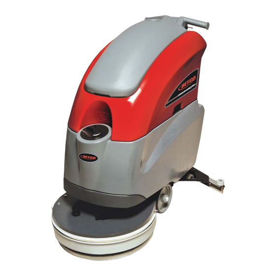
20" Automatic Scrubber
™
with Traction Drive
Scan this QR code to view
operator training video
Operator and Parts
Manual
400 Van Camp Road • Bowling Green, Ohio 43402
Customer Service: 888-GO-BETCO • Fax: 800-445-5056 • Technical Service: 877-856-5954 • www.betco.com
1
Advertisement
Table of Contents

Related Manuals for BETCO Stealth ASD20BT


Summary of Contents for BETCO Stealth ASD20BT
- Page 1 20” Automatic Scrubber ™ with Traction Drive Scan this QR code to view operator training video Operator and Parts Manual 400 Van Camp Road • Bowling Green, Ohio 43402 Customer Service: 888-GO-BETCO • Fax: 800-445-5056 • Technical Service: 877-856-5954 • www.betco.com...
-
Page 2: Table Of Contents
TABLE OF CONTENTS RECEIVING THE MACHINE........3 - 4 GENERAL SAFETY REGULATIONS ......... 5 MACHINE PREPARATION ........6 - 12 OPERATION ............13 - 14 TURNING OFF THE MACHINE ........15 DAILY MAINTENANCE ..........16 -17 WEEKLY MAINTENANCE ..........18 TROUBLESHOOTING ........... 19 BRUSH AND SELECTION USE........19 MAINTENANCE SCHEDULE.......... -
Page 3: Receiving The Machine
RECEIVING THE MACHINE Immediately check, when receiving the machine, that all the materials indicated on delivery documents have been received and also that the machine has not been damaged in transit. If it has been damaged, this damage must be immediately reported to the shipper and also to our customer’s service department. - Page 4 TECHNICAL DESCRIPTION Measurement Unit Stealth ASD20BT ™ Rated power HP (W) 1.5 (1100) Working width In (mm) 19.7 (500) Rear squeegee width In (mm) 29.2 (742) Work capacity ft2/h (m2/h) 22,050 (1450) Water consumption g/m2 Brush & Pad (diameter) in (mm) 20 (500) Brush RPM Brush pressure...
-
Page 5: General Safety Regulations
• Before using the machine make sure that all doors and covers are positioned as shown in this operating and maintenance manual. • When your BETCO machine is ready to be retired, the machine must be disposed of properly. It contain oils and electronic components. The machine was built using totally recyclable materials. -
Page 6: Machine Preparation
MACHINE PREPARATION 1. HANDLING THE PACKED MACHINE The machine is contained in specific packaging. It is not possible to place more than two packages on top of each other. The total weight is 220 lb. (100 kg). The overall dimensions of the package are: A : 45.1 in (1145 mm) B : 26.2 in (665 mm) C : 48.4 in (1230 mm) - Page 7 Weight 68 lb. (31 kg) WARNING: Your charger must be set according to the type of bat- tery you install. Call BETCO customer service to ensure correct charger setting after replacement batteries are installed. • The batteries must be handled using lifting and transportation means suitable for the weight and dimensions.
- Page 8 MACHINE PREPARATION 5. BATTERY MAINTENANCE For maintenance and recharging, follow the instructions provided by the battery manufacturer. 6. BATTERY DISPOSAL When the battery reaches the end of its working life, it must be disconnected by certified professional, and removed from the battery compartment. 7.
- Page 9 MACHINE PREPARATION 9. CONNECTING THE BATTERY CONNECTOR Connect the battery connector (2) to the machine connector (1) 10. BATTERY INDICATOR The battery indicator uses LEDs and has 8 positions (7 yellow - charged batter- ies, and 1 red - run down batteries). WARNING: A few seconds after the red indicator light comes on, the brush motor switches off automatically.
- Page 10 MACHINE PREPARATION 11. INSTRUMENT PANEL COMPONENTS The instrument panel components are identified as follows: A. Levers to activate brushes / traction (located beneath the handlebar) B. ON/OFF key switch C. Battery level / hour-counter display D. Traction speed control knob 12.
- Page 11 MACHINE PREPARATION 15. ADJUSTING THE SQUEEGEE HEIGHT The height of the squeegee must be adjusted based on wear of the squeegee blade. To do this, turn the knobs (2) counter clockwise to raise the squeegee, and clockwise to lower it. Note: the right and left wheels must be adjusted to the same level, so the squeegee can work parallel to the floor.
- Page 12 MACHINE PREPARATION 18. SOLUTION TANK Remove the front inlet cap and check the solution filter is correctly installed. Check the filter cap (beneath the solution tank, at the back) is correctly closed. 19. SOLUTION TANK Fill the tank with clean water in the front fill location (1) at a temperature not ex- ceeding 120°F (50°C).
-
Page 13: Operation
OPERATION 1. MACHINE OPERATION A. Connect the battery plug to the machine plug. B. Turn the key (1) of the main switch to the "ON" position (clockwise). The bat- tery charge level indicator lights will immediately come on. C. Turn on the water valve (2) (the water dispenses automatically when the brush is turning). -
Page 14: Operation
OPERATION 2. REVERSE MOVEMENT To move the machine in reverse push the switch levers (1) forward. WARNING: When moving the machine in reverse, raise the squeegee. 3. OVERFLOW DEVICE The machine has a float in a filter basket that trips when the recovery tank is full to stop airflow into the vacuum hose. -
Page 15: Turning Off The Machine
SHUTTING DOWN THE MACHINE 1. END OF WORK When shutting down the machine and before you perform any type of mainte- nance: A. Turn off the solution control valve (1) B. Raise the brush deck using the foot pedal (2) C. -
Page 16: Daily Maintenance
DAILY MAINTENANCE 1. CLEANING THE RECOVERY TANK A. Raise the vacuum cover (1). B. Remove the drain hose (2) from it's hook and empty the tank. C. Rinse the inside of the tank with water. D. Close the cover on the machine and replace the drain hose cap and drain hose. -
Page 17: Daily Maintenance
DAILY MAINTENANCE 4. CLEANING THE SQUEEGEE To clean: A. Remove the vacuum hose from the squeegee shoe adaptor. B. Loosen the knobs (1) at the squeegee shoe adapter. C. Remove and clean the squeegee shoe adapter. D. Carefully clean inside the squeegee shoe. E. -
Page 18: Weekly Maintenance
WEEKLY MAINTENANCE 1. CLEANING THE SQUEEGEE HOSE Every week, or whenever vacuum seems to be unsatisfactory, check the squee- gee hose for obstructions. To clean it: A. Remove the vacuum hose from the squeegee shoe adapter on the squeegee shoe. B. -
Page 19: Troubleshooting
TROUBLESHOOTING GUIDE INSUFFICIENT WATER ON THE PAD 1. Check the valve – located beneath the symbol – (1) is turned on. 2. Check there is water in the solution tank. THE MACHINE DOES NOT CLEAN WELL 1. Check the wear of the scrubbing pad and, if necessary, replace it. THE SQUEEGEE DOES NOT DRY WELL 1. -
Page 20: Maintenance Schedule
MAINTENANCE SCHEDULE RECOMMENDED SERVICE Stealth ASD20B INTERVALS (HOURS) DAILY 100 200 400 1,000 BATTERIES Check water level add if necessary DAILY Check cleanless of machine battery tray ELECTRIC Check tightness of electric contacts and fuses Check state of electric cables crossing the machine SOLUTION TANK t l i f... -
Page 21: Wear Items Listing
WEAR ITEMS LISTING Wear Items - Before Serial Number 214999999 Wear Items - After Serial Number 215000000 Part # Description Part # Description E88268 Pad Driver E82320 Pad Driver E88330 Brush, General Purpose 20" 0.3mm E83033 Brush, General Purpose 20" 0.3mm E88269 Brush, Medium Duty 20"... -
Page 22: Parts Diagrams And Listings
BRUSH DECK DIAGRAM - BEFORE SERIAL NUMBER 214999999... - Page 23 BRUSH DECK PARTS LISTING - BEFORE SERIAL NUMBER 214999999 Item# Part # Description Qty. Item# Part # Description Qty. E83802 Hex Bolt M8x30 Zinc E88272 Brush Deck Splash Guard E20073 Brush Deck E81709 Nyloc Hex Nut, M8 Zinc E83970 Bushing E83404 Flat Washer M9x24x2.5 Zinc...
- Page 24 BRUSH DECK DIAGRAM - AFTER SERIAL NUMBER 215000000...
- Page 25 BRUSH DECK PARTS LISTING - AFTER SERIAL NUMBER 215000000 Item# Part # Description Qty. Item# Part # Description Qty. E84318 Brush Deck Housing E83970 Bushing E83035 Brush, Heavy Duty 20" 0.7mm E82309 Spring, 11.8x1.2x15mm Zinc Compression E83033 Brush, General Purpose 20" 0.3mm E83802 Hex Bolt M8x30 Zinc E82320...
- Page 26 BRUSH DECK DRIVE DIAGRAM - BEFORE SERIAL NUMBER 214999999 19.11 19.1...
- Page 27 BRUSH DECK DRIVE PARTS LISTING - BEFORE SERIAL NUMBER 214999999 Item# Part # Description Qty. Item# Part # Description Qty. E20011 Motor Mount Plate E82845 Spacer E82312 Bushing E88245 Motor, Geared 24V 400W 140 RPM E83833 Hex Bolt M8x25 Zinc 19.11 E20451 Fitting, Solution Delivery Tube...
- Page 28 BRUSH DECK DRIVE DIAGRAM - AFTER SERIAL NUMBER 215000000 8.1 8.2 4.4.1 4.4.2...
- Page 29 BRUSH DECK DRIVE PARTS LISTING - AFTER SERIAL NUMBER 215000000 Item# Part # Description Qty. Item# Part # Description Qty. E84326 Threaded Rod E20123 Lock Washer M5x1.6 Zinc E22639 Tubing, 1.25" E83799 Flat Washer M6.6x18x2 SS E84327 Tubing, 6.5" E81874 Flat Washer M8x17x1.6 Zinc E22640 Cable Sheath...
- Page 30 SQUEEGEE ASSEMBLY DIAGRAM - BEFORE SERIAL NUMBER 214999999...
- Page 31 SQUEEGEE ASSEMBLY PARTS LISTING - BEFORE SERIAL NUMBER 214999999 Item# Part # Description Qty. Item# Part # Description Qty. E83909 Squeegee Blade, Polyurethane 30" x 1 3/4" x 1/8" 1 E82253 Bushing, Brass OD 11.95mm x ID 8.9mm x L 8.45mm 1 E12560 Squeegee Blade, Polyurethane 30 3/4"...
- Page 32 SQUEEGEE ASSEMBLY DIAGRAM - AFTER SERIAL NUMBER 215000000...
- Page 33 SQUEEGEE ASSEMBLY PARTS LISTING - AFTER SERIAL NUMBER 215000000 Item# Part # Description Qty. Item# Part # Description Qty. E84336 Mounting Stud E22352 Center Front Squeegee Blade Clamp E22637 Squeegee Blade Kit, 31" E22635 Clamp, Front Squeegee Blade E84277 Squeegee Blade Kit, Poly, 31" E22355 Center Rear Squeegee Blade Clamp E84278...
- Page 34 SQUEEGEE YOKE DIAGRAM - BEFORE SERIAL NUMBER 214999999...
- Page 35 SQUEEGEE YOKE PARTS LISTING - BEFORE SERIAL NUMBER 214999999 Item# Part # Description Qty. Item# Part # Description Qty. E83590 Chain E82279 Spring E83655 Adjuster Knob E88279 Micro Switch Sealed E20373 Guide Bushing E20286 Squeegee Yoke E20227 Squeegee Yoke ASM E85499 Hex Nut, M8x6.5 SS E20644...
- Page 36 SQUEEGEE YOKE DIAGRAM - AFTER SERIAL NUMBER 215000000...
- Page 37 SQUEEGEE YOKE PARTS LISTING - AFTER SERIAL NUMBER 215000000 Item# Part # Description Qty. Item# Part # Description Qty. E20006 Bushing E83824 Square Nut, M8 SS E88279 Micro Switch Sealed E81673 Nut, Hex Nyloc, M3 Zinc E20408 Squeegee Lift Lever E81342 Nut, Hex Jam, Nyloc, M8 SS E84339...
- Page 38 MAIN FRAME DIAGRAM - BEFORE SERIAL NUMBER 214999999...
- Page 39 MAIN FRAME PARTS LISTING - BEFORE SERIAL NUMBER 214999999 Item# Part # Description Qty. Item# Part # Description Qty. E20071 Clamp Plate E82834 Pivot Block E81735 Hex Bolt M12x35 Zinc E20501 Splash Guard E83829 Hex Jam Nut, M12X7 Zinc E20108 Screw, Pan Hd Phil Self Tap M4.8x16 SS E83550 NyLoc Hex Nut, M6 Zinc...
- Page 40 MAIN FRAME DIAGRAM - AFTER SERIAL NUMBER 215000000...
- Page 41 MAIN FRAME PARTS LISTING - AFTER SERIAL NUMBER 215000000 Item# Part # Description Qty. Item# Part # Description Qty. E88253 Bushing E20108 Screw, Pan Hd Phil Self Tap M4.8x16 SS E20006 Bushing E20246 Flat Hd Soc Machine Screw M6x50 Zinc E22002 Screw, M8 x 30 E83597...
- Page 42 TRANSAXLE DIAGRAM - AFTER SERIAL NUMBER 215000000 14.1.1...
- Page 43 TRANSAXLE PARTS LISTING - AFTER SERIAL NUMBER 215000000 Item# Part # Description Qty. Item# Part # Description Qty. E88253 Bushing E20108 Screw, Pan Hd Phil Self Tap M4.8x16 SS E20006 Bushing E20246 Flat Hd Soc Machine Screw M6x50 Zinc E22002 Screw, M8 x 30 E83597 Brush Deck Lift Idler Arm Weldment...
- Page 44 SOLUTION TANK DIAGRAM 1.14 1.18 1.12 1.17.1 1.17 1.11 1.19 1.17.2 1.17.3 1.17.2 1.17.3 1.15 1.16...
- Page 45 SOLUTION TANK PARTS LISTING Item# Part # Description Qty. Item# Part # Description Qty. 1.18 E20577 Spacer E20285 Solution Tank ASM E88258 Hose, Glass Reinforced 15 OD x 10 ID x 496 L 1.19 E20602 Fitting, Barbed Threaded E20409 Foot Pedal Latch Plate E20411 Bracket E20611...
- Page 46 RECOVERY TANK DIAGRAM 3.10 3.11.2 3.11.1...
- Page 47 RECOVERY TANK PARTS LISTING Item# Part # Description Qty. Item# Part # Description Qty. E88499 Hose, Vacuum 3.11.2 E20188 Hinge Pin E20074 Hinge Pin E83833 Hex Bolt M8x25 Zinc E82638 Screw, Pan Hd Phil Self Tap M3.9x13 SS E20354 Recovery Tank ASM E20189 Fitting, Barbed E82808...
- Page 48 VACUUM UNIT DIAGRAM 2.27 2.19 2.11 2.13 2.30 2.26 2.29 2.14 2.23 2.18 2.17 2.15 2.10 2.16 2.24 2.22 2.28 2.12 2.25 2.26 2.20.2 2.21 2.20.1 2.20.3 2.20 2.20.4...
- Page 49 VACUUM UNIT PARTS LISTING Item# Part # Description Qty. Item# Part # Description Qty. 2.19 E20064 Support Bracket E20265 Plate E20066 Recovery Tank Cover ASM 2.20 E88291 Vacuum Motor 24VDC 310W E20305 Mounting Ring 2.20.1 E83897 Connector, Electrical Housing 30A E20652 Sound Deadening Foam 2.20.2...
- Page 50 SOLUTION DELIVERY DIAGRAM...
- Page 51 SOLUTION DELIVERY PARTS LISTING Item# Part # Description Qty. Item# Part # Description Qty. E20602 Fitting, Threaded Barb E81035 Solenoid Valve E85762 Hose Clamp E22145 Fitting, 3/8" - 1/4" Reducer E22144 Tubing, 10 ID x 370 L E88829 Fitting, 90 Degree Elbow E20375 Tubing, 10 ID x 650 L...
- Page 52 HANDLEBAR DIAGRAM - BEFORE SERIAL NUMBER 214999999 27.3 27.7 3.13 27.7 27.6 3.14 27.4 27.5 27.8 27.1 3.13 27.2 3.12 3.16 3.15 26.1 3.11 3.11 26.2 3.12 3.22 3.23 3.19 3.20 3.13 3.10 3.21 3.17 3.10...
- Page 53 HANDLEBAR PARTS LISTING - BEFORE SERIAL NUMBER 214999999 Item# Part # Description Qty. Item# Part # Description Qty. E88301 Lever, Right Switch E20200 Handlebar Housing E82351 Key switch E87296 Drain Hose Clip E83316 Key Switch E83836 Hex Bolt M5x16 Zinc E83316 Key Switch E20121...
- Page 54 HANDLEBAR DIAGRAM - AFTER SERIAL NUMBER 215000000 1.47 1.37 1.14 1.46 1.40 1.15 1.27 1.36 1.45 1.39 1.41 1.42 1.24 1.10 1.17 1.23 1.17 1.22 1.25 1.16 1.12 1.44 1.23 1.22 1.16 1.31 1.19 1.15 1.28 1.12 1.29 1.13 1.29 1.11 1.3.3 1.26...
- Page 55 HANDLEBAR PARTS LISTING - AFTER SERIAL NUMBER 215000000 Item# Part # Description Qty. Item# Part # Description Qty. E20330 Ball Stud M10x22.5 1.25 E20362 Set Screw Hex Soc Dog Point M5x30 Zinc 1.26 E20298 Soc Button Head Screw M5x16 SS E20574 Bushing 1.27...
-
Page 56: Electrical System
ELECTRICAL DIAGRAM - BEFORE SERIAL NUMBER 214999999... -
Page 57: Battery Check Card, Hour Meter
ELECTRICAL PARTS LISTING - BEFORE SERIAL NUMBER 214999999 Item# Part # Description Item# Part # Description E20402 Electrical Connector 30A E88293 Battery Check Card, Hour Meter E82351 Key Switch Assembly w/Keys E20402 Electrical Connector 30A E20646 Chopper Card E20713 Potentiometer E88266 Relay Card E83972... - Page 58 ELECTRICAL DIAGRAM - AFTER SERIAL NUMBER 215000000...
- Page 59 ELECTRICAL PARTS LISTING - AFTER SERIAL NUMBER 215000000 Item# Part # Description Qty. Item# Part # Description Qty. Various Batteries E20713 Potentiometer Various Battery Charger Dilution Control Commutator Card (Not Used) Dilution Control Card (Not Used) Fuse E83316 Key Switch E81035 Solenoid Valve E84353...
- Page 60 ELECTRICAL DIAGRAM - BEFORE SERIAL NUMBER 214999999 Potentiometer TRACTION MOTOR VACUUM BRUSH MOTOR MOTOR ADJUSTMENT/INSPECTIONS OF THE VARIABLE SPEED CONTROL CARD 1. Verify the functionality of the variable speed control card. 2. If necessary adjust the traction card: • Lift up at least one of the traction wheel . •...
- Page 61 BATTERY CHECK CARD / HOUR METER - AFTER SERIAL NUMBER 215000000 1. Verify that when turning on the machine, the battery discharge indicator has the following starting sequence: • For the first 2 seconds, display the setting of the dip switches. •...
-
Page 62: Solution Tank Inspections
BATTERY CHECK CARD / HOUR METER - BEFORE SERIAL NUMBER 214999999 1. Verify that turning on the machine the battery check card has the follow- ing starting sequence: • Turning on of the LED which correspond to the set-up (red LED = “0”). •... -
Page 63: Vacuum System Inspection
VACUUM SYSTEM INSPECTION 1. Verify the cleanness and functionality of the float filter. 2. Check the air sealing of the vacuum unit on the recovery tank. 3. Verify the connections and the sealing of the vacuum hoses and the squeegee hoses. -
Page 64: Brush Base Adjustment
BRUSH BASE ADJUSTMENT Verify the right inclination of the brush deck adjust. To adjust the brush deck adjust as follows: • Lower the brush deck to the floor with a brush installed. • Loosen the M8 bolt and the M8 nut that attach the brush deck to the left arm. -
Page 65: Squeegee Adjustment
SQUEEGEE ADJUSTMENT 1. Adjust the inclination adjuster of the squeegee blade until the blade has a common inclination over its entire length. 2. Adjust the height of the wheels using the knob checking that the blade has an inclination between 30 and 45 degrees. 3. -
Page 68: Warranty
Service Distributor. If the original part is returned within the warranty policy period from date of delivery for inspection by Betco and is found to be defective the owner will be credited for the cost of replacement parts plus shipping and handling.
Need help?
Do you have a question about the Stealth ASD20BT and is the answer not in the manual?
Questions and answers