Table of Contents
Advertisement
Available languages
Available languages
Quick Links
Advertisement
Chapters
Table of Contents

Related Manuals for ProLights Lumipix12Q


Summary of Contents for ProLights Lumipix12Q
-
Page 1: User Manual
LUMIPIX12Q DIGITAL PIXEL-LED QUAD BATTEN Manuale Utente User Manual... - Page 2 Music & Lights S.r.l. si riserva ogni diritto di elaborazione in qualsiasi forma delle presenti istruzioni per l’uso. La riproduzione - anche parziale - per propri scopi commerciali è vietata. Al fine di migliorare la qualità dei prodotti, la Music&Lights S.r.l. si riserva la facoltà di modificare, in qualunque momento e senza preavviso, le specifiche menzionate nel presente manuale di istruzioni.
-
Page 3: Table Of Contents
3. 16 Informazioni sul dispositivo 3. 17 Ripristino impostazioni dispositivo 4 Manutenzione 4. 1 Manutenzione e pulizia del sistema ottico 4. 2 Risoluzione dei problemi Certificato di garanzia Contenuto dell'imballo: • LUMIPIX12Q • Staffa di fissaggio (2pz.) • Manuale utente... -
Page 4: Sicurezza
LUMIPIX 12Q ATTENZIONE! Prima di effettuare qualsiasi operazione con l’unità, leggere con attenzione questo manuale e conservarlo accuratamente per riferimenti futuri. Contiene informazioni importanti riguardo l’installazione, l’uso e la manutenzione dell’unità. SICUREZZA Avvertenze generali • I prodotti a cui questo manuale si riferisce sono conformi alle Direttive della Comunità Europea e per- tanto recano la sigla . -
Page 5: Informazioni Generali
LUMIPIX 12Q INFORMAZIONI GENERALI Spedizioni e reclami Le merci sono vendute “franco nostra sede” e viaggiano sempre a rischio e pericolo del distributore/clien- te. Eventuali avarie e danni dovranno essere contestati al vettore. Ogni reclamo per imballi manomessi dovrà essere inoltrato entro 8 giorni dal ricevimento della merce. Garanzie e resi Il prodotto è... -
Page 6: Introduzione
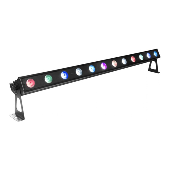
- 1 - INTRODUZIONE 1.1 DESCRIZIONE LUMIPIX12Q è un cambiacolori lineare, munito di 12 LED RGBW/FullColor (8W ciascuno) ad alta efficienza luminosa e in formato da 0,5mt. Il sistema di gestione è personalizzabile, in linea con le esigenze di utilizzo, da 4 a 48 canali di gestione in modalità... -
Page 7: Elementi Di Comando E Di Collegamento
LUMIPIX 12Q 1.3 ELEMENTI DI COMANDO E DI COLLEGAMENTO Vista frontale FUSE: T 2 A, 250V DMX IN MENU ENTER DOWN DMX OUT LumiPix 2Q POWER OUT POWER IN: 100~240V AC, 50/60Hz Dettaglio vista posteriore Fig.2 1. STAFFA DI MONTAGGIO 7. -
Page 8: Installazione
- 2 - INSTALLAZIONE 2.1 MONTAGGIO LUMIPIX12Q può essere collocato su un piano solido. Inoltre, grazie alle possibilità di fissaggio sulla dop- pia staffa (fig.3), l’unità può essere montata anche a testa in giù, su una traversa. Per il fissaggio occorrono dei supporti robusti per il montaggio. -
Page 9: Funzioni E Impostazioni
- 3 - FUNZIONI E IMPOSTAZIONI 3.1 FUNZIONAMENTO Per accendere il LUMIPIX12Q, inserire la spina del cavo di alimentazione in una presa di rete (240V~ 50Hz). L’unità può essere comandata da un unità DMX di comando luce oppure svolgere autonomamente il suo programma. -
Page 10: Struttura Menu
LUMIPIX 12Q 3.3 STRUTTURA MENU MENU (LEVEL 1) (LEVEL 2) (LEVEL 3) (LEVEL 4) DMX Address DMX Address < 001 > < 001 - 512 > DMX Channel DMX Channel < 4 ch > < 4 ch > < 6 ch > <... - Page 11 LUMIPIX 12Q < G B W > < R G B W > < Manu C > Manual Color Value < R = 255 > < R = 255 > < G = 255 > < G = 255 > <...
-
Page 12: Modalità Auto Show
• Sull’unità master selezionare il programma desiderato come indicato al paragrafo 3.4. • Servirsi dei connettori DMX del LUMIPIX12Q e di un cavo XLR per formare una catena di unità. In certe condizioni e lunghezze si consiglia di effettuare una terminazione come mostrato a pagina 14. -
Page 13: Configurazione Canale Dmx
DMX per il primo canale DMX. Se, per esempio, sull’unità di comando è previsto l’indirizzo 33 per coman- dare la funzione del primo canale DMX, si deve impostare sul LUMIPIX12Q l’indirizzo di start 33. Le altre funzioni del pannello saranno assegnate automaticamente agli indirizzi successivi. -
Page 14: Collegamenti Della Linea Dmx
LUMIPIX 12Q 3.10 COLLEGAMENTI DELLA LINEA DMX La connessione DMX è realizzata con connettori standard XLR. Utilizzare cavi schermati, 2 poli ritorti, con impedenza 120Ω e bassa capacità. Per il collegamento fare riferimento allo schema di connessione riportato di seguito: DMX - INPUT DMX - OUTPUT Spina XLR... -
Page 15: Tabella Canali Dmx
LUMIPIX 12Q 3.12 TABELLA CANALI DMX CH Function in CH4 mode Value CH Function in CH8 mode Value 0% - 100% 000 - 255 0% - 100% 000 - 255 GREEN GREEN 0 - 100% 000 - 255 0 - 100% 000 - 255 BLUE BLUE... - Page 16 LUMIPIX 12Q CH24 CH Function in CH24 mode Value 0% - 100% 000 - 255 GREEN 0 - 100% 000 - 255 LED1 BLUE 0 - 100% 000 - 255 WHITE 0 - 100% 000 - 255 0% - 100% 000 - 255 GREEN 0 - 100%...
-
Page 17: Funzioni Dispositivo
LUMIPIX 12Q 3.13 FUNZIONI DISPOSITIVO Per il LUMIPIX12Q è possibile accedere alle seguenti funzioni dispositivo: Dimmer • Per entrare nella modalità dimmer e scegliere e simulare diverse curve dimming, premere il tasto MENU ripetutamente fino a quando sul display non compare [DIMMER MODE], quindi premere il tasto ENTER. -
Page 18: Informazioni Sul Dispositivo
LUMIPIX 12Q • Premere il tasto MENU ripetutamente fino a quando sul display non compare [INFO] quindi premere ENTER per confermare. • Selezionare attraverso i tasti UP/DOWN la funzione [AUTO TEST] • Per confermare e dare l’avvio al test automatico premere il tasto ENTER. Manual Test Permette di eseguire tramite pannello comandi delle regolazioni sugli effetti per ottenere una perfetta uniformità... -
Page 19: Manutenzione
LUMIPIX 12Q - 4 - MANUTENZIONE 4.1 MANUTENZIONE E PULIZIA DEL SISTEMA OTTICO • Durante gli interventi, assicurarsi che l’area sotto il luogo di installazione sia libera da personale non qualificato. • Spegnere l’unità, scollegare il cavo di alimentazione ed aspettare finché l’unità non si sia raffreddata. • Tutte le viti utilizzate per l’installazione dell’unità... - Page 21 3. 14 White calibration 3. 15 Fixture test 3. 16 Fixure information 3. 17 Reset function 4 Maintenance 4. 1 Maintenance and cleaning the unit 4. 2 Trouble shooting Warranty Packing content • LUMIPIX12Q • Mount bracket (2pc.) • User manual...
-
Page 22: Safety
LUMIPIX 12Q WARNING! Before carrying out any operations with the unit, carefully read this instruction manual and keep it with cure for future reference. It contains important information about the installation, usage and maintenance of the unit. SAFETY General instruction • The products referred to in this manual conform to the European Community Directives and are there- fore marked with . -
Page 23: General Information
LUMIPIX 12Q GENERAL INFORMATION Shipments and claims The goods are sold “ex works” and always travel at the risk and danger of the distributor. Eventual dam- age will have to be claimed to the freight forwarder. Any claim for broken packs will have to be forwarded within 8 days from the reception of the goods. -
Page 24: Introduction
0,5mt format. Control system is customizable allowing “Pixel Control”, independent selection of each LED, from 4 to 48 channels. LUMIPIX12Q offers advanced possibilities in effect generation as LED video or sound activated arrays. 1.2 TECHNICAL SPECIFICATIONS Light source and optics • 12 x 8W RGBW/FC high-efficiency LEDS... -
Page 25: Operating Elements And Connections
LUMIPIX 12Q 1.3 OPERATING ELEMENTS AND CONNECTIONS Front view FUSE: T 2 A, 250V DMX IN MENU ENTER DOWN DMX OUT LumiPix 2Q POWER OUT POWER IN: 100~240V AC, 50/60Hz Zoom rear view Fig.2 1. MOUNTING BRACKET 6. POWER IN (Neutrik connector) for connection 2. -
Page 26: Installation
2.1 MOUNTING LUMIPIX12Q may be set up on a solid and even surface. The unit can also be mounted upside down to a cross arm. For fixing, stable mounting clips are required. The mounting place must be of sufficient stability and be able to support a weight of 10 times of the unit’s weight. -
Page 27: Functions And Settings
LUMIPIX 12Q - 3 - FUNCTIONS AND SETTINGS 3.1 OPERATION Connect the supplied main cable to a socket (100-240 VAC-50/60 Hz). Then the unit is ready for operation and can be operated via a DMX controller or it independently performs its show program in succession. To switch off, disconnect the mains plug from the socket. -
Page 28: Menu Structure
LUMIPIX 12Q 3.3 MENU STRUCTURE MENU (LEVEL 1) (LEVEL 2) (LEVEL 3) (LEVEL 4) DMX Address DMX Address < 001 > < 001 - 512 > DMX Channel DMX Channel < 4 ch > < 4 ch > < 6 ch > <... - Page 29 LUMIPIX 12Q < G B W > < R G B W > < Manu C > Manual Color Value < R = 255 > < R = 255 > < G = 255 > < G = 255 > <...
-
Page 30: Auto Show Mode
LUMIPIX 12Q 3.4 SHOW MODE If no DMX control signal is present at the DMX INPUT, the unit independently runs through its show pro- gramme provided that the blackout mode is switched off: • Press the button MENU so many times until the display shows [AUTO SHOW], then press the button ENTER. • Press the button UP/DOWN to switch between the show (AUTO 1 - AUTO 12, FADE). -
Page 31: Dmx Configuration
• Press the MENU button to go back or to meet the waiting time to exit the setup menu. To able to operate the LUMIPIX12Q with a light controller, adjust the DMX start address for the first a DMX channel. If e. g. address 33 on the controller is provided for controlling the function of the first DMX channel, adjust the start address 33 on the LUMIPIX12Q. -
Page 32: Connection Of The Dmx Line
LUMIPIX 12Q 3.10 CONNECTION OF THE DMX LINE DMX connection employs standard XLR connectors. Use shielded pair-twisted cables with 120Ω imped- ance and low capacity. The following diagram shows the connection mode: DMX - INPUT DMX - OUTPUT XLR plug XLR socket Pin1 : GND - Shield Pin2 : - Negative... -
Page 33: Dmx Control
LUMIPIX 12Q 3.12 DMX CONTROL CH Function in CH4 mode Value CH Function in CH8 mode Value 0% - 100% 000 - 255 0% - 100% 000 - 255 GREEN GREEN 0 - 100% 000 - 255 0 - 100% 000 - 255 BLUE BLUE... - Page 34 LUMIPIX 12Q CH24 CH Function in CH24 mode Value 0% - 100% 000 - 255 GREEN 0 - 100% 000 - 255 LED1 BLUE 0 - 100% 000 - 255 WHITE 0 - 100% 000 - 255 0% - 100% 000 - 255 GREEN 0 - 100%...
-
Page 35: Fixture Settings
LUMIPIX 12Q 3.13 FIXTURE SETTINGS It is possible to change the parameter value in the following way: Dimmer • Enter in Dimmer mode to select specific dimming curve, press the button MENU so many times until shows [DIMMER MODE], and press the button ENTER to confirm. • Press the button UP/DOWN to select [MODE 1 - MODE2 - MODE3]. -
Page 36: Fixure Information
LUMIPIX 12Q • Press the button MENU so many times until shows [INFO], then press the ENTER button to confirm. • Using the button UP/DOWN to select [AUTO TEST]. • To confirm and start the automatic test press the ENTER button. Manual Test Allows you to adjust effects from the control panel to obtain perfect uniformity between the projectors. -
Page 37: Maintenance
LUMIPIX 12Q - 4 - MAINTENANCE 4.1 MAINTENANCE AND CLEANING THE UNIT • Make sure the area below the installation place is free from unwanted persons during setup. • Switch off the unit, unplug the main cable and wait until the unit has cooled down. • All screws used for installing the device and any of its parts should be tightly fastened and should not be corroded. - Page 39 Place Stamp Here Affrancare Spett.le Music&Lights S.r.l. Via Appia Km 136.200 04020 Itri (LT) Italy "...
- Page 44 Music & Lights S.r.l. entertainment technologies Via Appia km 136,200 - 04020 Itri (LT) ITALY ISO 9001:2008 tel. +39 0771 72190 fax +39 0771 721955 Certified Company www.musiclights.it info@musiclights.it...
Need help?
Do you have a question about the Lumipix12Q and is the answer not in the manual?
Questions and answers