Table of Contents
Advertisement
Quick Links
Advertisement
Table of Contents

Related Manuals for FOR-A RS-HD808


Summary of Contents for FOR-A RS-HD808
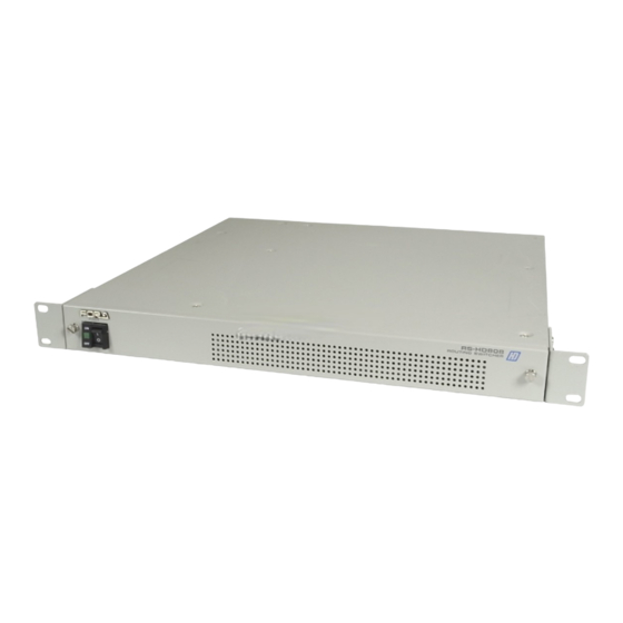
- Page 1 OPERATION MANUAL RS-HD808 Routing Switcher *S/*C Edition...
- Page 3 Precautions Important Safety Warnings [Power] Operate unit only on the specified supply voltage. Caution Disconnect power cord by connector only. Do not pull on cable portion. Do not place or drop heavy or sharp-edged objects on power cord. A damaged cord can cause fire or electrical shock hazards.
- Page 4 [Circuitry Access] Do not remove covers, panels, casing, or access circuitry with power applied to the unit! Turn power off and disconnect power cord prior to removal. Internal servicing / adjustment of unit should only be performed by qualified personnel. Do not touch any parts / circuitry with a high heat factor.
-
Page 5: Rack Mounting
RS-HD series units are fully inspected and adjusted prior to shipment and can be operated immediately upon completing all required connections and operational settings. Check your received items against the packing list below. ITEM REMARKS RS-HD808 AC cord/AC cord clip 1ea. To secure AC power cord to unit Connector assembly... -
Page 6: Table Of Contents
Table of Contents 1. Prior to Starting ........................1 1-1. Welcome ........................... 1 1-2. About the RS-HD series ....................1 1-3. About This Manual ......................1 2. Panel Descriptions ........................2 2-1. Front Panel........................2 2-2. Rear Panel ........................3 3. -
Page 7: Prior To Starting
Provides an economical solution to video signal routing requirements. 1-3. About This Manual This manual is intended to help the user easily operate the RS-HD808 and make full use of its functions during operations. Before connecting or operating your unit, read this operation manual thoroughly to ensure you understand the product. -
Page 8: Panel Descriptions
2. Panel Descriptions 2-1. Front Panel ① Where: ① Power Switch and Indicator Switch used to turn unit power ON / OFF. Power indication will be lit green whenever power switch is ON and power is applied to the unit. -
Page 9: Rear Panel
2-2. Rear Panel ③ ④ ⑤ ① ⑧ ⑦ ⑥ ② Where: ① INPUT Connectors Used for SDI (component or composite) or HD SDI video input connection from VTRs or other system video equipment. (Input format auto detected.) BNC connectors. ②... -
Page 10: Set Up
3. Set up 3-1. Board Settings Depending on your system configuration, settings for dipswitches and jumpers on the internal CPU and MAIN boards may have to be changed from factory defaults. 3-1-1. Accessing Internal CPU IMPORTANT Always switch unit power OFF and disconnect power cord before accessing unit interior to make setting changes. - Page 11 ④ Refer to sec. (See sec. 3-3 ‘CPU Settings’.) following and make settings on The MTX board and CPU as required for your system configuration. Front edge JP11 ACV NOR BF NOR ⑤ The layout of the MTX Switches S1 and S2 are shown below. MTX S1 Front edge ⑥...
-
Page 12: Removal And Adjustment Of The I/F Card
3-2. Removal and Adjustment of the I/F Card Use the following procedure when removing the I/F board. ① Remove the screw located on the back panel and removed the I/F card by pulling the I/F card out through the front. The jumpers are located inside the I/F Card. -
Page 13: Cpu Settings
3-3. CPU Settings Once you have accessed the internal CPU board, dipswitches and jumpers will be located on the board as indicated in the figure below. ① Dipswitch and Jumper Locations. Front edge JP11 ACV NOR BF NOR ② SW1 Settings Note that if you have more than one unit configured in your system, SW1-1, SW1-2 and SW1-3 factory settings must be changed to a different ID setting unless the unit is used as the master unit. - Page 14 SW1-4, SW1-5 and SW1-6 Combined settings determine signal switchover level of unit. Unit Level SW1-4 SW1-5 SW1-6 (* Factory setting is to level 1.) SW1-7 SW1-7 is also used to return all crosspoints to factory defaults. To return crosspoint settings to INn = OUTn factory defaults (IN1 = OUT1, IN2 = OUT2, etc., where n equals 1-8) follow the procedure in table below.
- Page 15 ④ JP2 Settings Used to set REMOTE connector to RS-232C or RS-422 protocol when controlling RS-HD series units via the REMOTE connector or computer command. Setting here must be to the same protocol as set at SW1-8 (② above). If not, you cannot remote control the unit. Front panel REMOTE connector to RS-422 Front panel...
-
Page 16: Mtx Settings
3-4. MTX settings The following settings are preset at the factory. DO NOT change any of these settings. card MTX card MTX S1 Front edge ① MTX Card:S1 1 2 3 4 5 6 7 8 All dipswitches are preset OFF at the factory before shipping. ②... -
Page 17: Connection
4. Connection 4-1. Reference Connection The REF IN connectors must be used to connect the same reference signal between all units configured in your routing system. If external reference used for all router units External reference signal Master Loopthru from REF IN Slave Loopthru from REF IN... -
Page 18: Reference Switching Point Signals
4-1-1. Reference Switching Point Signals REF IN external sync input signal should appear as one of the forms below for your particular system. HD signals are shown below [ 1 0 8 0 i ] Switching point ス イ ッ チ ン グ ポ イ ン ト 1123 1124 1125... -
Page 19: Connection
4-2. Connection 4-2-1. AC Power Cord Securing Clip Use the AC Power Cord Securing Clip included with your unit to ensure the AC power cord remains securely connected to the unit. ① Connect AC power cord to AC IN on the unit rear panel. From the right side of AC cord connector base, slide clip around AC connector cord. -
Page 20: Basic Connection
◇ Video Setting VTR1 User fabricated fan alarm device Digital video input External reference VTR8 RS-HD808 Looped thru REF IN signal Digital Digital or internally generated reference signal Monitor 8 Monitor 1... -
Page 21: Computer Control Connection
Crosspoint switchover settings can be made via computer command using either RS-232C or RS-422 protocol via the REMOTE connector. Digital video input VTR8 External reference RS-HD808 Digital Digital Looped thru REF IN signal Monitor 1 Monitor 8 or internally generated... -
Page 22: Rs-Ru Series Remote Control Connection
System expansion can be achieved by connecting to RS-RU series remote control and display unit. (Refer to a "4-3. System Configuration Example" to connect more than one unit.) RS-RU Series Remote control unit (Optional) RS-HD808 POWER AC100-120V - 50/60Hz IN REMOTE... -
Page 23: System Configuration Example
8 input x 8 output digital video + 2 lines of stereo audio routed using 3 remote control units and 2 display units. To set up this system, the units below are required. RS-HD808 × 1ea. (video router support) RS-A808 × 2 ea. (audio router support) RS-RU72JCD ×... - Page 24 System example External reference RS-RU72JCD REMOTE CONTROL UNIT LEVEL SOURCE DESTINATION/SETUP RS-HD808 ENTER ID = 0 (master) SETUP Level = 1 (digital video) RS-RU72JCD ID = 3 Level = 1, 2 (video / audio synced switchover) RS-A808 RS-RU36JCD REMOTE CONTROL UNIT...
-
Page 25: Alarm Connector
4-4. ALARM Connector The RS-HD808 also has a fan alarm connector. This connector should be used for fan alarm output when the front panel power switch is not easily visible. Connector Appearance HR10A-7R-6S (Hirose) connector (female) Pin Assignment Pin No. - Page 26 ALARM OUT signal specs Max. Voltage Max. Amp 30VDC 0.75A NOTE HR10A-7P-6P (Hirose) connector (male) is included with this unit for user cable fabrication at RS-HD808 side connection.
-
Page 27: Remote Connector
Connector pin assignments will be as follows based on which protocol setting is made; RS-232C or RS-422. If set to RS-232C IMPORTANT Max. allowable cable length between RS-HD808 and computer is 15 m when RS-232C protocol is used. Signal direction Pin No. - Page 28 Signal direction Pin No. Signal Computer- RS-HD Signal ground (SG) Signal ground (SG) Signal ground (SG) ← Transmit B (T+) → Receive A (R-) Frame ground (FG) Cabling An example of computer cable connection for control via REMOTE interface when it is set to RS-232C protocol is shown below.
-
Page 29: Control Operation
5. Control Operation 5-1. General RS-HD series units can be controlled via computer command when REMOTE interface at rear panel is set to RS-232C or RS-422 operation. Computer controlled crosspoints can be freely selected by command and are maintained at configured routing switchers by a backup battery when power is switched OFF or lost. -
Page 30: Operational Flow
5-4. Operational Flow Responses An example of RS-HD series routing response flow is given below. POWER ON Initialization Upload of crosspoint data will start when power is switched ON. Status confirmation Crosspoint settings confirmed / changed and routing performed once every sec. New crosspoint routing requested? Send control command... - Page 31 Command Logic An example of command logic flow is given below. New crosspoint routing requested Control command sent to RS-HD series unit (This point corresponds to ‘Send control command’ block in ‘Responses’ previous.) More than 1 sec. RS-HD series unit since control returns a response command sent?
-
Page 32: Rs-232C Control Commands
5-5. RS-232C Control Commands 5-5-1. Command Blocks Command blocks are as below when RS-232C protocol employed. All commands are ASCII code (HEX indications given following). ① ② ③ ④ Where: ① Channel type code V → Video signal ASCII 56 ②... -
Page 33: Output Off
5-5-2. Output Off If crosspoint selection is performed using the command sequence given below, no video will be output from the selected output. This effectively lets you turn video output off by setting a crosspoint with no input connection. Command blocks are as below when RS-232C protocol employed. -
Page 34: Status Request Commands
5-5-3. Status Request Commands Command blocks are as below to confirm crosspoint selection status. All commands are ASCII code (HEX indications given following). ① ② ③ Where: ① Channel type code V → Video signal ASCII 56 ② Control Code R →... -
Page 35: Response Commands
5-5-4. Response Commands Normal receive ① When starting switchover command. ASCII ② Status command received if RS-HD808 operation normal. S is command response indicating normally received. SPACE ASCII (If input channel 4 switched to output.) SPACE ASCII (If no input channel selected.) Error Receive E is command response indicating an error has occurred. -
Page 36: Control Commands And Ascii Codes
5-5-5. Control Commands and ASCII Codes Commands for controlling routing switchers in system configuration are as follows: Command ASCII Code Item To select channel type Control code setting. S→For normal switchover R→Status request Crosspoint Response command from routing switcher: Command ASCII Code Item Output when command is normally... -
Page 37: Rs-232C Control Commands
The ‘RS Control Command’ manual contains a complete list of RS-232C control commands that can be used to computer control your entire routing system of FOR-A routing switcher units. Which commands are valid for your system will depend on which of FOR-A’s routing products are configured in your system. -
Page 38: If Problems Occur
6. If Problems Occur If any of the following problems occur during operation of your RS-HD series unit, proceed as indicated below to see if the problem can be corrected before assuming a unit malfunction has occurred. Problem Check Action Power switch / Verify power is ON and power cord securely cord... -
Page 39: Specifications & Dimensions
7. Specifications & Dimensions 7-1. Unit Specifications Inputs / Outputs 8 x 8 Video Input SD – HD SDI / 143Mbps – 1.5Gbps, (auto reclock at 1.5Gpbs) 75Ω, 8 ea., BNC. Input Return Loss 5MHz–1/2fc: 15dB higher 1/2fc–fc: 10dB higher (fc = HD data clock frequency at 1.485 GHz) Cable compensation Up to 100m when 5C-FB equivalent cable used. -
Page 40: External Dimensions
7-2. External Dimensions (All dimensions in mm) - Page 41 Warning This equipment has been tested and found to comply with the limits for a Class A digital device, pursuant to Part 15 of FCC Rules. These limits are designed to provide reasonable protection against harmful interference when the equipment is operated in a commercial environment. This equipment generates, uses, and can radiate radio frequency energy and, if not installed and used in accordance with the instruction manual, may cause harmful interference to radio communications.
- Page 42 Two Executive Drive, Suite 670, Fort Lee Executive Park, Fort Lee NJ 07024, USA Phone: +1 (201) 944-1120 Fax : +1 (201) 944-1132 FOR-A America Distribution & Service Center 2400 N.E. Waldo Road, Gainesville, FL 32609, USA Phone: +1 352-371-1505 Fax: +1 352-378-5320...
Need help?
Do you have a question about the RS-HD808 and is the answer not in the manual?
Questions and answers