Cincoze CV-100 User Manual
Convertible panel pc
Hide thumbs
Also See for CV-100:
- User manual (44 pages) ,
- User manual (41 pages) ,
- User manual (44 pages)
Table of Contents
Advertisement
Quick Links
Advertisement
Table of Contents

Subscribe to Our Youtube Channel
Related Manuals for Cincoze CV-100


Summary of Contents for Cincoze CV-100
-
Page 2: Table Of Contents
CV-100/P1000 Series | User’s Manual Convertible Panel PC Contents Prefaces Revision …………………………………………………..……………….….…….. 03 Copyright Notice …………………………………………………………………… 03 Acknowledgement ……………………………………………………..... 03 Disclaimer ………………………………………………………….……………….. 03 Declaration of Conformity ……………………………………….………………… 03 Product Warranty Statement ……………………………………….…………….. 04 Technical Support and Assistance ………………………………….……………. 04 Conventions Used in this Manual …………………………………….………….. 04 Safety Precaution …..…………………………………….…………….………….. - Page 3 CV-100/P1000 Series | User’s Manual Convertible Panel PC Chapter 3 System Setup 3.1 Removing the Top Cover ……...…………………………..…………... 28 3.2 Installing a Half Size Mini PCIe Card ………………………………..29 3.3 Installing a Full Size Mini PCIe Card ………………..……………..30 3.4 Installing Antennas …………………………………..….……………..31 3.5 Installing a SO-DIMM ……………………………………..…….…..
-
Page 4: Revision
2015/01/13 Copyright Notice © 2014 by Cincoze Co., Ltd. All rights are reserved. No parts of this manual may be copied, modified, or reproduced in any form or by any means for commercial use without the prior written permission of Cincoze Co., Ltd. -
Page 5: Product Warranty Statement
1 Year Before sending your product in, you will need to fill in Cincoze RMA Request Form and obtain a RMA number from us. Our staff is available at any time to provide you with the most friendly and immediate service. -
Page 6: Technical Support And Assistance
| User’s Manual Convertible Panel PC Prefaces Technical Support and Assistance 1. Visit the Cincoze website at www.cincoze.com/support.php where you can find the latest information about the product. 2. Contact your distributor or our technical support team or sales representative for technical support if you need additional assistance. -
Page 7: Safety Precaution
CV-100/P1000 Series | User’s Manual Convertible Panel PC Prefaces Safety Precautions Before installing and using this device, please note the following precautions: 1. Read these safety instructions carefully. 2. Keep this User’s Manual for future reference. 3. Disconnected this equipment from any AC outlet before cleaning. -
Page 8: Package Contents
CV-100/P1000 Series | User’s Manual Convertible Panel PC Prefaces Package Contents Before installation, please ensure all the items listed in the following table are included in the package. CV-108/P1001 Q’ty Item Description CV-108/P1001 Panel PC Panel Mounting Kit Utility DVD Driver... - Page 9 CV-100/P1000 Series | User’s Manual Convertible Panel PC Prefaces CV-115/P1001 Q’ty Item Description CV-115/P1001 Panel PC Panel Mounting Kit Utility DVD Driver DIO Terminal Block Connector (Female) Power Terminal Block Connector (Female) HDD Screw Pack Mini PCIe Screw Pack CV-W115/P1001 Q’ty...
-
Page 10: Ordering Information
CV-100/P1000 Series | User’s Manual Convertible Panel PC Prefaces CV-119/P1001 Q’ty Item Description CV-119/P1001 Panel PC Panel Mounting Kit Utility DVD Driver DIO Terminal Block Connector (Female) Power Terminal Block Connector (Female) HDD Screw Pack Mini PCIe Screw Pack Ordering Information Model No. -
Page 11: Optional Accessories
CV-100/P1000 Series | User’s Manual Convertible Panel PC Prefaces Optional Accessories Model No. Product Description GSM60A12-CIN Adapter AC/DC 12V 5A 60W with 3pin Terminal Block Plug 5.0mm Pitch, GSM60A12-P1J SL2-SL3 US 2 heads power cord, US B type to IEC C13, SVT 18AWG/3C Black 1.8M SL-2+SL-3 EU 2 heads power cord, EU G type to IEC C13, H05VV-F 0.75mm2/3G Black 1.8M SL-... -
Page 12: Chapter 1 Product Introductions
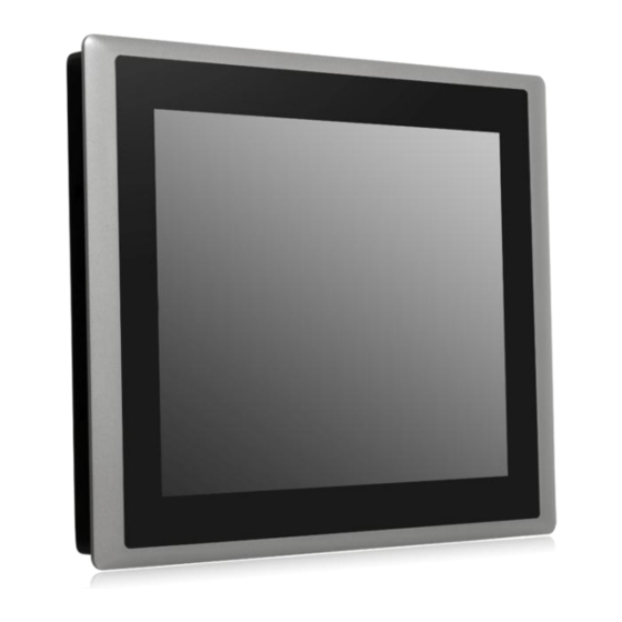
Chapter 1 Product Introductions... - Page 13 Chapter 1: Product Introductions 1.1 Overview The CV-100/P1000 series all-in-one panel PC offers LED backlight LCD. It features flat surface and IP65 dust/waterproof front panel. In addition, designed with aluminum die-casting front frame with rugged body structure that can be able to apply in industrial applications. The CV-100/P1000 series supports Convertible Display System (CDS) technology which makes it more flexible in system maintaining and upgrading.
-
Page 14: Cv-108/P1001
CV-100/P1000 Series | User’s Manual Convertible Panel PC Chapter 1: Product Introductions 1.1.1 CV-108/P1001 Key Features • 8.4" TFT SVGA 4:3 LCD with Resistive 5-wire Touch • Designed with Aluminum Die-Casting Front Frame • Onboard Intel® Atom™ E3845 Processor Quad Core, 1.91GHz •... -
Page 15: Cv-110/P1001
CV-100/P1000 Series | User’s Manual Convertible Panel PC Chapter 1: Product Introductions 1.1.2 CV-110/P1001 Key Features • 10.4" TFT SVGA 4:3 LCD with Resistive 5-wire / Projected Capacitive Touch • Designed with Aluminum Die-Casting Front Frame • Onboard Intel® Atom™ E3845 Processor Quad Core, 1.91GHz •... -
Page 16: Cv-112/P1001
CV-100/P1000 Series | User’s Manual Convertible Panel PC Chapter 1: Product Introductions 1.1.3 CV-112/P1001 Key Features • 12.1" TFT SVGA 4:3 LCD with Resistive 5-wire / Projected Capacitive Touch • Designed with Aluminum Die-Casting Front Frame • Onboard Intel® Atom™ E3845 Processor Quad Core, 1.91GHz •... -
Page 17: Cv-115/P1001
CV-100/P1000 Series | User’s Manual Convertible Panel PC Chapter 1: Product Introductions 1.1.4 CV-115/P1001 Key Features • 15" TFT XGA 4:3 LCD with Resistive 5-wire / Projected Capacitive Touch • Designed with Aluminum Die-Casting Front Frame • Onboard Intel® Atom™ E3845 Processor Quad Core, 1.91GHz •... -
Page 18: Cv-W115/P1001
CV-100/P1000 Series | User’s Manual Convertible Panel PC Chapter 1: Product Introductions 1.1.5 CV-W115/P1001 Key Features • 15.6" TFT WXGA 16:9 LCD with Resistive 5-wire / Projected Capacitive Touch • Designed with Aluminum Die-Casting Front Frame • Onboard Intel® Atom™ E3845 Processor Quad Core, 1.91GHz •... -
Page 19: Cv-117/P1001
CV-100/P1000 Series | User’s Manual Convertible Panel PC Chapter 1: Product Introductions 1.1.6 CV-117/P1001 Key Features • 17" TFT SXGA 4:3 LCD with Resistive 5-wire / Projected Capacitive Touch • Designed with Aluminum Die-Casting Front Frame • Onboard Intel® Atom™ E3845 Processor Quad Core, 1.91GHz •... -
Page 20: Cv-119/P1001
CV-100/P1000 Series | User’s Manual Convertible Panel PC Chapter 1: Product Introductions 1.1.7 CV-119/P1001 Key Features • 19" TFT SXGA 4:3 LCD with Resistive 5-wire / Projected Capacitive Touch • Designed with Aluminum Die-Casting Front Frame • Onboard Intel® Atom™ E3845 Processor Quad Core, 1.91GHz •... -
Page 21: System I/O
CV-100/P1000 Series | User’s Manual Convertible Panel PC Chapter 1: Product Introductions 1.2 System I/O 1.2.1 Front Power on/off switch CFast and SIM card Slot Press to power-on or power-off the system Used to insert a CFast card and SIM card... -
Page 22: Side (Left)
CV-100/P1000 Series | User’s Manual Convertible Panel PC Chapter 1: Product Introductions 1.2.3 Side (Left) USB 3.0 port Digital I/O Terminal Block Used to connect USB 3.0/2.0/1.1 device The Digital I/O terminal block supports 4 digital input and 4 digital output USB 2.0 port... -
Page 23: Top
CV-100/P1000 Series | User’s Manual Convertible Panel PC Chapter 1: Product Introductions 1.2.5 Top VESA Mounting Hole These are mounting holes for VESA mount (75x75mm and 100x100mm) 1.3 Mechanical Dimensions Unit: mm CV-108/P1001... - Page 24 CV-100/P1000 Series | User’s Manual Convertible Panel PC Chapter 1: Product Introductions Unit: mm CV-110/P1001...
- Page 25 CV-100/P1000 Series | User’s Manual Convertible Panel PC Chapter 1: Product Introductions Unit: mm CV-112/P1001...
- Page 26 CV-100/P1000 Series | User’s Manual Convertible Panel PC Chapter 1: Product Introductions Unit: mm CV-115/P1001...
- Page 27 CV-100/P1000 Series | User’s Manual Convertible Panel PC Chapter 1: Product Introductions Unit: mm CV-W115/P1001...
- Page 28 CV-100/P1000 Series | User’s Manual Convertible Panel PC Chapter 1: Product Introductions Unit: mm CV-117/P1001...
- Page 29 CV-100/P1000 Series | User’s Manual Convertible Panel PC Chapter 1: Product Introductions Unit: mm CV-119/P1001...
-
Page 30: Chapter 2 Jumpers And Connectors
Chapter 2 Jumpers and Connectors... -
Page 31: Jumper Settings
CV-100/P1000 Series | User’s Manual Convertible Panel PC Chapter 2: Jumpers and Connectors 2.1 Jumpers Settings When setting the jumpers, ensure that the jumper caps are placed on the correct pins. When the jumper cap is placed on both pins, the jumper is short. If you remove the jumper cap, or place the jumper cap on just one pin, the jumper is open. -
Page 32: Bottom View
CV-100/P1000 Series | User’s Manual Convertible Panel PC Chapter 2: Jumpers and Connectors 2.2.2 Bottom View... - Page 33 CV-100/P1000 Series | User’s Manual Convertible Panel PC Chapter 2: Jumpers and Connectors 2.3 Connector / Jumper / Switch Definition List of Connector / Jumper / Switch Connector Location Definition AT_ATX1 AT / ATX Power Mode Switch BL_PWR1 Backlight Power on / off switching...
-
Page 34: Switch Definition
CV-100/P1000 Series | User’s Manual Convertible Panel PC 2.4 Switches Definitions AT_ATX1: AT / ATX Power Mode Switch Switch Definition 1-2 (Right) ATX Power Mode(Default) 2-3 (Left) AT Power Mode CLR_CMOS1: Clear BIOS Switch Switch Definition Normal Status (Default) Clear BIOS... -
Page 35: Jumper Definition
CV-100/P1000 Series | User’s Manual Convertible Panel PC 2.5 Jumpers Definitions COM12_SEL1: COM1 / COM2 with Power Select Connector Type: 2X5 10-pin Header, 2.0mm pitch COM1 COM2 Definition Definition 1-3 On 2-4 On 3-5 On +12V 4-6 On +12V 7-9 On... - Page 36 CV-100/P1000 Series | User’s Manual Convertible Panel PC COM1_1: RS232 / RS422 / RS485 Connector Connector Type: 9-pin D-Sub RS232 RS422 / 485 Full RS485 Half Duplex Definition Duplex Definition Definition DCD1 TX1- DATA1- RxD1 TX1+ DATA1+ TxD1 RX1+ DTR1...
- Page 37 CV-100/P1000 Series | User’s Manual Convertible Panel PC DC_IN1: DC Power Input Connector (+9~48V) Connector Type: Terminal Block 1X3 3-pin, 5.0mm pitch Definition +9~48VIN Chassis GND DIO1: Digital Input / Output Connector Connector Type: Terminal Block 1X10 10-pin, 3.5mm pitch...
- Page 38 CV-100/P1000 Series | User’s Manual Convertible Panel PC DP1: DisplayPort Connector Definition Definition DP_LANE0_P DP_LANE3_N DP_LANE0_N DP_LANE1_P DP_AUX_P DP_LANE1_N DP_LANE2_P DP_AUX_N DP_HPD DP_LANE2_N DP_LANE3_P DP_PWR...
- Page 39 CV-100/P1000 Series | User’s Manual Convertible Panel PC LAN1: RJ45 with LEDs Port Definition Definition LAN1_MDI0P LAN1_MDI2N LAN1_MDI0N LAN1_MDI1N LAN1_MDI1P LAN1_MDI3P LAN1_MDI2P LAN1_MDI3N Act LED Status Definition Link LED Status Definition Blinking Yellow Data Activity Steady Green 1Gbps Network Link...
- Page 40 CV-100/P1000 Series | User’s Manual Convertible Panel PC LINE_OUT1: Line-out Jack (Green) MIC1: Microphone Jack (Pink) Connector Type: 5-pin Phone Jack Connector Type: 5-pin Phone Jack Definition Definition OUT_R MIC_R OUT_L MIC_L MINIPCIE1: Mini PCI-Express Socket Definition Definition Definition WAKE# +3.3V...
- Page 41 CV-100/P1000 Series | User’s Manual Convertible Panel PC POWER1: Power Connector PWR_SW1:Power Switch Connector Connector Type: 1X4-pin Wafer, 2.0mm pitch Definition Definition Power Button +12V SATA1: SATA with Power Connector Definition Definition SATA_TX1+ SATA_TX1- SATA_RX1- SATA_RX1+ +3.3V +3.3V +12V +3.3V...
- Page 42 CV-100/P1000 Series | User’s Manual Convertible Panel PC SPK_L1: Left Internal Speaker Connector SPK_R1: Right Internal Speaker Connector Definition Definition OUT_L Power Button USB1_2_1:USB2.0 Connector, Type A Definition Definition USB_DATA0- USB_DATA_1- USB_DATA0+ USB_DATA_1+ USB2_1: USB2.0 Connector, Type A Definition USB2_DATA1- USB2_DATA1+ USB3_1: USB 3.0 Connector, Type A...
-
Page 43: Chapter 3 System Setup
Chapter 3 System Setup... -
Page 44: Removing The Top Cover
CV-100/P1000 Series | User’s Manual Convertible Panel PC Chapter 3: System Setup 3.1 Removing the Top Cover In order to prevent electric shock or system damage, before removing the chassis cover, must turn off power and disconnect the unit from power source. -
Page 45: Installing A Half Size Mini Pcie Card
CV-100/P1000 Series | User’s Manual Convertible Panel PC Chapter 3: System Setup 3.2 Installing a Half Size Mini PCIe Card 1. Locate the Mini PCIe socket. 2. Use provided two screws on bracket to fasten the module and bracket together. -
Page 46: Installing A Full Size Mini Pcie Card
CV-100/P1000 Series | User’s Manual Convertible Panel PC Chapter 3: System Setup 4. Press down the module and use the two screws to fix the module. 3.3 Installing a Full Size Mini PCIe Card 1. Locate the Mini PCIe socket. -
Page 47: Installing Antennas
CV-100/P1000 Series | User’s Manual Convertible Panel PC Chapter 3: System Setup 3. Press down the module and use the two screws to fix the module. 3.4 Installing Antennas 1. Remove the antenna hole covers at front panel. 2. Have antenna jack penetrate through the hole. - Page 48 CV-100/P1000 Series | User’s Manual Convertible Panel PC Chapter 3: System Setup 3. Put on washer and fasten the nut with antenna jack. 4. Assemble the antenna and antenna jack together. 5. Attach the RF connector at another end of cable onto the module.
-
Page 49: Installing A So-Dimm
CV-100/P1000 Series | User’s Manual Convertible Panel PC Chapter 3: System Setup 3.5 Installing a SO-DIMM 1. Locate SO-DIMM socket. 2. Tilt the SODIMM module at a 45 degree angle and insert it to SODIMM socket until the gold-pated connector of module contacted firmly with the socket. -
Page 50: Installing The Top Cover
CV-100/P1000 Series | User’s Manual Convertible Panel PC Chapter 3: System Setup 3.6 Installing the Top Cover 1. Put on the cover. 2. Fasten the 8 screws to fix the cover. -
Page 51: Installing A Sata Hard Drive
CV-100/P1000 Series | User’s Manual Convertible Panel PC Chapter 3: System Setup 3.7 Installing a SATA Hard Drive 1. Locate the removable HDD bay and loosen the 2 screws. 2. Pull out the HDD bracket. 3. Make the PCB side of the HDD face up, place the HDD bracket on it. Ensure the direction of bracket is correct and use 4 provided screws to assemble HDD and HDD bracket together. -
Page 52: Installing A Sim Card
CV-100/P1000 Series | User’s Manual Convertible Panel PC Chapter 3: System Setup 4. Align the HDD bracket with the entrance of HDD bay. And insert the HDD bracket until the connector of HDD contact the SATA connector firmly. 3.8 Installing a SIM Card 1. -
Page 53: Installing A Cfast Card
CV-100/P1000 Series | User’s Manual Convertible Panel PC Chapter 3: System Setup 3.9 Installing a CFast Card 1. Locate the CFast card slot. 2. Remove the mounting cover by unscrewing the two screws. 3. Insert the CFast card. -
Page 54: Connecting With Cv Display Module
CV-100/P1000 Series | User’s Manual Convertible Panel PC Chapter 3: System Setup 3.10 Connecting with CV Display Module 1. Locate the module connector slot. 2. Turn over the unit to have the bottom side face up, loosen the 2 screws of the module connector bracket. - Page 55 CV-100/P1000 Series | User’s Manual Convertible Panel PC Chapter 3: System Setup 3. Connect the modules. 4. Fasten the 6 screws to fix the PC module on the display module.
-
Page 56: Chapter 4 Bios Setup
Chapter 4 BIOS Setup... -
Page 57: Bios Introduction
CV-100/P1000 Series | User’s Manual Convertible Panel PC Chapter 4: BIOS Setup 4.1 BIOS Introduction The BIOS (Basic Input/Output System) is a program located on a Flash Memory on the motherboard. When you start the computer, the BIOS program will gain control. The BIOS first... -
Page 58: Main Setup
CV-100/P1000 Series | User’s Manual Convertible Panel PC Chapter 4: BIOS Setup 4.2 Main Setup Press <Del> to enter BIOS CMOS Setup Utility, the Main Menu (as shown below) will appears on the screen. Use arrow keys to move among the items and press <Enter> to accept or enter a sub-menu. -
Page 59: Advanced Setup
CV-100/P1000 Series | User’s Manual Convertible Panel PC Chapter 4: BIOS Setup 4.3 Advanced Setup 4.3.1 ACPI Settings Enable or disable ACPI Auto Configuration. 59 59... -
Page 60: Super Io Configuration
CV-100/P1000 Series | User’s Manual Convertible Panel PC Chapter 4: BIOS Setup 4.3.2 Super IO Configuration You can use this screen to select options for the Super IO Configuration, and change the value of the selected option. ■ Serial Port 1 Configuration ... - Page 61 CV-100/P1000 Series | User’s Manual Convertible Panel PC Chapter 4: BIOS Setup ■ Serial Port 2 Configuration Serial Port This item will allow users to enable or disable serial port. COM2 Mode Select Change the Serial interface. Select <RS232>, <RS422> or <RS485> interface.
-
Page 62: Hardware Monitor
CV-100/P1000 Series | User’s Manual Convertible Panel PC Chapter 4: BIOS Setup 4.3.3 Hardware Monitor These items display the current status of all monitored hardware devices/ components such as voltages and temperatures. 4.3.4 Serial Port Console Redirection Console Redirection This item allows users to enable or disable console redirection. -
Page 63: Cpu Configuration
CV-100/P1000 Series | User’s Manual Convertible Panel PC Chapter 4: BIOS Setup 4.3.5 CPU Configuration ■ Socket 0 CPU Information This section provides information on your CPU, frequency, and cache memory. ■ Active Processor Cores Change the active processor cores. Select <All> or <1> mode. -
Page 64: Ppm Configuration
CV-100/P1000 Series | User’s Manual Convertible Panel PC Chapter 4: BIOS Setup 4.3.6 PPM Configuration ■ EIST Enable or disable Intel SpeedStep. ■ CPU C state Report Enables or disables support for CPU's power-saving functions. ■ Enhanced C state Enables or disables Intel CPU Enhanced Halt (C1E) function, a CPU power-saving function in system halt state. -
Page 65: Thermal Configuration
CV-100/P1000 Series | User’s Manual Convertible Panel PC Chapter 4: BIOS Setup 4.3.7 Thermal Configuration ■ Critical Trip Point Allows user to set the CPU temperature threshold. If the CPU temperature reaches this value, the operating system will shut down the system. This item is configurable only when DTS is enabled. -
Page 66: Ide Configuration
CV-100/P1000 Series | User’s Manual Convertible Panel PC Chapter 4: BIOS Setup 4.3.8 IDE Configuration ■ Serial-ATA (SATA) This item will allow users to enable or disable Serial ATA. ■ SATA Mode This item will allow users to select IDE or AHCI Mode. -
Page 67: Compatibility Support Module Configuration
CV-100/P1000 Series | User’s Manual Convertible Panel PC Chapter 4: BIOS Setup 4.3.9 Compatibility Support Module Configuration ■ CSM Support Enables or disables UEFI CSM (Compatibility Support Module) to support a legacy PC boot process. ■ Boot option filter Allows user to select which type of operating system to boot. -
Page 68: Usb Configuration
CV-100/P1000 Series | User’s Manual Convertible Panel PC Chapter 4: BIOS Setup 4.3.10 USB Configuration ■ Legacy USB Support Allows USB keyboard/ mouse to be used in MS-DOS. ■ XHCI Hand-off Determines whether to enable XHCI (USB3.0) Hand-off feature for an operating system without XHCI (USB3.0) Hand-off support. -
Page 69: Chipset
CV-100/P1000 Series | User’s Manual Convertible Panel PC Chapter 4: BIOS Setup 4.4 Chipset 4.4.1 North Bridge This section provides information on the installed memory size and memory/onboard graphics- related configuration options. - Page 70 CV-100/P1000 Series | User’s Manual Convertible Panel PC Chapter 4: BIOS Setup ■ Intel IGD Configuration This section provides onboard graphics-related configuration options. GOP Driver This item will allow users to enable or disable GOP Driver. Integrated Graphics Device This item will allow users to enable or disable Integrated Graphics Device.
-
Page 71: South Bridge
CV-100/P1000 Series | User’s Manual Convertible Panel PC Chapter 4: BIOS Setup 4.4.2 South Bridge ■ Azalia HD Audio Control detection of the Azaliadevice. Audio Controller Enabled: Azalia will be unconditionally enabled. Disabled: Azalia will be unconditionally disabled. ■ USB Configuration ... - Page 72 CV-100/P1000 Series | User’s Manual Convertible Panel PC Chapter 4: BIOS Setup ■ PCI Express Configuration PCI Express Port 0 This item will allow users to enable or disable PCI Express Port 0. Speed Change the PCI Express interface speed. Select <AUTO> ,<Gen 2> or <Gen 1>...
-
Page 73: Security
CV-100/P1000 Series | User’s Manual Convertible Panel PC Chapter 4: BIOS Setup 4.5 Security This section allows you to configure and improve your system and allows you to set up some system features according to your preference. 4.5.1 Administrator Password Administrator Password controls access to the BIOS Setup utility. -
Page 74: Boot
CV-100/P1000 Series | User’s Manual Convertible Panel PC Chapter 4: BIOS Setup 4.6 Boot This section allows you to configure the boot settings. 4.6.1 Setup Prompt Timeout Use this item to set number of seconds to wait for setup activation key. -
Page 75: Save & Exit
CV-100/P1000 Series | User’s Manual Convertible Panel PC Chapter 4: BIOS Setup 4.7 Save & Exit This section allows you to configure the boot settings. 4.7.1 Save Changes and Reset This item allows user to reset system setup after saving changes. - Page 76 © 2014 Cincoze Co., Ltd. All rights reserved. The Cincoze logo is a registered trademark of Cincoze Co., Ltd. All other logos appearing in this catalog are the intellectual property of the respective company, product, or organization associated with the logo.
Need help?
Do you have a question about the CV-100 and is the answer not in the manual?
Questions and answers