
Related Manuals for ADLINK Technology GIE64+


Summary of Contents for ADLINK Technology GIE64+
- Page 1 GIE64+ 4-CH PoE GigE Vision Interface Card User’s Manual Manual Rev.: 4.00 Revision Date: July 17, 2013 Part No: 50-11245-1030 Advance Technologies; Automate the World.
-
Page 2: Revision History
Revision History Revision Release Date Description of Change(s) 2.00 Feb. 24, 2012 Initial release 2.10 Mar. 23, 2012 Minor spec changes 3.00 May 30, 2013 New product version release 4.00 July 17, 2013 Revision to new product version release... -
Page 3: Preface
GIE64+ Preface Copyright 2013 ADLINK Technology, Inc. This document contains proprietary information protected by copy- right. All rights are reserved. No part of this manual may be repro- duced by any mechanical, electronic, or other means in any form without prior written permission of the manufacturer. - Page 4 Conventions Take note of the following conventions used throughout this manual to make sure that users perform certain tasks and instructions properly. Additional information, aids, and tips that help users perform tasks. NOTE: NOTE: Information to prevent minor physical injury, component dam- age, data loss, and/or program corruption when trying to com- plete a task.
-
Page 5: Table Of Contents
GIE64+ Table of Contents Revision History..............ii Preface ..................iii List of Figures ............... vii List of Tables................ix 1 Introduction ................ 1 Overview................1 Features................1 Applications ................. 2 Specifications............... 2 1.4.1 Power over Ethernet Port ........... 2 1.4.2 General Specifications.......... - Page 6 This page intentionally left blank. Table of Contents...
-
Page 7: List Of Figures
GIE64+ List of Figures Figure 1-1: GIE64+ Schematic Diagram ..........4 Figure 1-2: GIE64+ Board Layout ............5 Figure 1-3: RJ-45 Ethernet Connector ..........5 Figure 1-4: Status LEDs..............6 Figure 1-5: Power Connector ............. 7 Figure 1-6: Card ID Switch Location ..........8 Figure 1-7: LED Status Indicator Location ........ - Page 8 This page intentionally left blank. viii List of Figures...
-
Page 9: List Of Tables
GIE64+ List of Tables Table 1-1: Board Layout Legend ............5 Table 1-2: RJ-45 Ethernet Port Connector Signals......6 Table 1-3: Status LED Legend ............7 Table 1-4: Power Connector Pin Assignments ......... 7 Table 1-5: ID Switch Position Legend..........9 Table 1-6: LED Status Indicator Display Definitions ....... - Page 10 This page intentionally left blank. List of Tables...
-
Page 11: Introduction
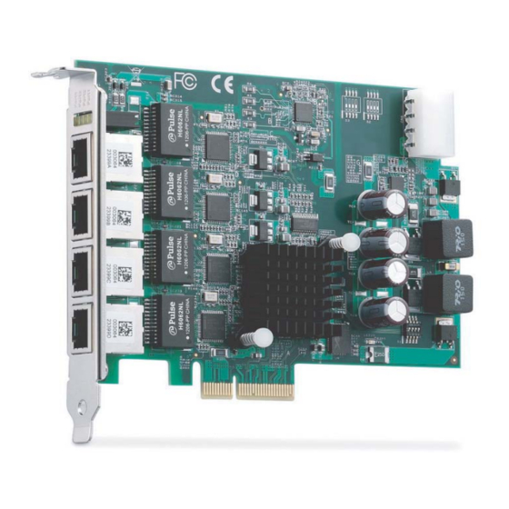
GIE64+ Introduction 1.1 Overview ® ADLINK's GIE64+ is a PCI Express x4 lane, PoE (Power over Ethernet) frame grabber with support for four independent Gigabit Ethernet ports. Multiple Gigabit Ethernet Vision device connec- tions are supported for standard Gigabit Ethernet Vision data transfer rates of up to 1000 Mb/s. -
Page 12: Applications
1.3 Applications The GIE64+ is ideally suited to frame grab functions in a wide vari- ety of applications, including: Machine Vision Inspection systems Scientific research instrumentation Medical research instrumentation The GIE64+ Function Library Reference can be downloaded from the product’s pages at http://www.adlinktech.com NOTE: NOTE: 1.4 Specifications... -
Page 13: General Specifications
GIE64+ 1.4.2 General Specifications Function Description Input voltage: 3.3VDC and 12VDC, (w/ PC system power) Input from power connector (see Figure 1-2): Max 7A @ 12VDC (support- Power Requirements ing up to 4 ports at 15.4W per PoE port) Input from PCIe slot: Max 2.1 A @ 12VDC (compatible to PCIe Spec), with connec- tion cut off by fuse when exceeded PCI Express... -
Page 14: I/O And Indicators
1.5 I/O and Indicators All dimensions shown are in mm NOTE: NOTE: 101.26 Figure 1-1: GIE64+ Schematic Diagram Introduction... -
Page 15: Ethernet Port
GIE64+ Figure 1-2: GIE64+ Board Layout PCIe lane RJ-45 Ethernet Ports PoE Status LED Power Connector Table 1-1: Board Layout Legend 1.5.1 RJ-45 Ethernet Port Figure 1-3: RJ-45 Ethernet Connector Introduction... -
Page 16: Status Leds
Signal MDI0+ (PoE_DC48V) MDI0- (PoE_DC48V) MDI1+ (PoE_DC0V) MDI2+ (PoE_DC48V) MDI2- (PoE_DC48V) MDI1- (PoE_DC0V) MDI3+ (PoE_DC0V) MDI3- (PoE_DC0V) Table 1-2: RJ-45 Ethernet Port Connector Signals 1.5.2 Status LEDs Figure 1-4: Status LEDs Introduction... -
Page 17: Power Connector
GIE64+ The GIE64+ provides four yellow LEDs to indicate operating con- ditions of the four PoE ports, as shown, with corresponding status as follows. Status ON: Port 1 PoE On OFF: Port 1 PoE Off ON: Port 2 PoE On OFF: Port 2 PoE Off ON: Port 3 PoE On OFF: Port 3 PoE Off... -
Page 18: Card Id Switch (S1)
1.5.4 Card ID Switch (S1) The GIE64+ is equipped with a card ID switch allowing identifica- tion of individual cards in a multi-card system. Figure 1-6: Card ID Switch Location Introduction... -
Page 19: Table 1-5: Id Switch Position Legend
GIE64+ S1 Slider S1 Slider Table 1-5: ID Switch Position Legend Introduction... -
Page 20: Onboard Led Status Indicators
1.5.5 Onboard LED Status Indicators 9 LEDs on the rear side of the GIE64+ indicate the data stream for each port, as follows. Figure 1-7: LED Status Indicator Location Status Definition Abnormal, PCIe switch downstream function is disabled. 1, 2, 3, 4 Blinking Normal Abnormal, PCIe switch downstream... -
Page 21: Table 1-6: Led Status Indicator Display Definitions
GIE64+ Status Definition Normal Abnormal, PCIe switch has unexpected error Table 1-6: LED Status Indicator Display Definitions Default status of LEDs 1-4 is blinking, for LEDs 5-8 lit or blink- ing, and LED 9 OFF. If the GIE64+ is malfunctioning and abnormal LED behavior, board damage may haver occurred. - Page 22 This page intentionally left blank. Introduction...
-
Page 23: Getting Started
GIE64+ Getting Started 2.1 Unpacking Checklist Before unpacking, check the shipping carton for any damage. If the shipping carton and/or contents are damaged, inform your dealer immediately. Retain the shipping carton and packing materials for inspection. Obtain authorization from your dealer before returning any product to ADLINK. - Page 24 8. Power up the computer. The GIE64+ can be installed in a PCI Express x4, x8, or x16 slot. ® Please download the Intel 82574L driver from: NOTE: NOTE: downloadcenter.intel.com Getting Started...
-
Page 25: Important Safety Instructions
GIE64+ Important Safety Instructions For user safety, please read and follow all instructions, WARNINGS, CAUTIONS, and NOTES marked in this manual and on the associated equipment before handling/operating the equipment. Read these safety instructions carefully. Keep this user’s manual for future reference. Read the specifications section of this manual for detailed information on the operating environment of this equipment. - Page 26 Never attempt to fix the equipment. Equipment should only be serviced by qualified personnel. A Lithium-type battery may be provided for uninterrupted, backup or emergency power. Risk of explosion if battery is replaced with one of an incorrect type. Dispose of used batteries appropriately. WARNING: Equipment must be serviced by authorized technicians when:...
-
Page 27: Getting Service
5215 Hellyer Avenue, #110, San Jose, CA 95138, USA Tel: +1-408-360-0200 Toll Free: +1-800-966-5200 (USA only) Fax: +1-408-360-0222 Email: info@adlinktech.com ADLINK Technology (China) Co., Ltd. Address: (201203) 300 Fang Chun Rd., Zhangjiang Hi-Tech Park, Pudong New Area, Shanghai, 201203 China Tel: +86-21-5132-8988 Fax:... - Page 28 84 Genting Lane #07-02A, Cityneon Design Centre, Singapore 349584 Tel: +65-6844-2261 Fax: +65-6844-2263 Email: singapore@adlinktech.com ADLINK Technology Singapore Pte. Ltd. (Indian Liaison Office) Address: 1st Floor, #50-56 (Between 16th/17th Cross) Margosa Plaza, Margosa Main Road, Malleswaram, Bangalore-560055, India Tel: +91-80-65605817, +91-80-42246107 Fax: +91-80-23464606 Email: india@adlinktech.com...
Need help?
Do you have a question about the GIE64+ and is the answer not in the manual?
Questions and answers