Table of Contents
Advertisement
Quick Links
Advertisement
Table of Contents

Related Manuals for Ledj Slimline CW Series


Summary of Contents for Ledj Slimline CW Series
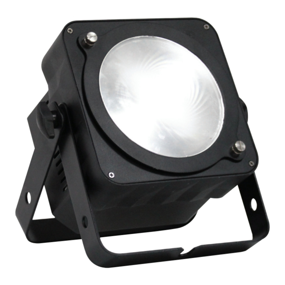
- Page 1 Slimline CW & WW Series 1 x 20W COB LED User Manual Convection Optional White housing cooled, IR remote versions no fan! Order ref: LEDJ90E Order codes: LEDJ61 - 1CW20 Black housing LEDJ61A - 1CW20 White housing LEDJ62 - 1WW20 Black housing LEDJ62A - 1WW20 White housing...
-
Page 2: Safety Advice
Safety advice WARNING FOR YOUR OWN SAFETY, PLEASE READ THIS USER MANUAL CAREFULLY BEFORE YOUR INITIAL START-UP! • Before your initial start-up, please make sure that there is no damage caused during transportation. • Should there be any damage, consult your dealer and do not use the equipment. • To maintain the equipment in good working condition and to ensure safe operation, it is necessary for the user to follow the safety instructions and warning notes written in this manual. • Please note that damages caused by user modifications to this equipment are not subject to warranty. CAUTION! CAUTION! TAKE CARE USING KEEP THIS EQUIPMENT THIS EQUIPMENT! AWAY FROM RAIN, HIGH VOLTAGE-RISK MOISTURE AND LIQUIDS OF ELECTRIC SHOCK!! IMPORTANT:... - Page 3 Product overview & technical specifications Slimline CW & WW COB Series Housing a 20W COB LED, the Slimline series gives smooth, even light across the wide 60° beam angle. Supplied with a removable 25° beam reduction lens the fixture offers greater versatility enabling rental companies to stock one product with two beam angle options. These units have rugged, all metal housing, side entry XLR and power connections and measure only 128mm in depth for easy transportation and installation. They can be operated in sound active, stand-alone, master/slave or DMX modes. • 1 x 20W cool white (6500K) or warm white (3200K) COB LED • Interchangeable beam angle: 25°or 60° (field angle: 80°) • 3000Hz refresh rate • DMX channels: 1 or 2 selectable • Static colour, colour change, colour fade, auto run, sound active and master/slave modes • 0 - 100% dimming with variable strobe • Bracket allows for multiple rigging or floor standing applications • Recessed rear control panel and rubber feet allow the panel to sit flat on the floor for uplighting • 4 push button menu with LED display • 3-pin XLR in/out sockets • IEC Power in/out sockets • Side entry XLR and power connections • Convection cooled • Optional IR remote (LEDJ90E) White housing CW version WW version 25° - Lux 5850 1831 25°...
-
Page 4: Technical Specifications
Technical specifications POWER IN POWER OUT DMX OUT DMX IN WW rear panel MODE ENTER DOWN SLIMLINE 1CW20 www.prolight.co.uk POWER IN POWER OUT DMX OUT DMX IN MODE ENTER DOWN SLIMLINE 1WW20 CW rear panel www.prolight.co.uk In the box: 1 x fixture, 01 - Bracket 05 - Function buttons 09 - IEC power out socket 1 x 25° lens, 02 - Bracket tightening knobs 06 - DMX input socket 10 - Fuse 1A 250V... -
Page 5: Dimming Mode
Operating instructions DMX channel mode: Operating in a DMX control mode environment gives the user the greatest flexibility when it comes to customising or creating a show. In this mode you will be able to control each individual trait of the fixture and each fixture independently. A001 To access the DMX channel mode, press the “MODE” button on the rear of the unit to show on the LED display. Now press the “ENTER” button and use the “UP” and “DOWN” buttons to set the desired DMX address. Now press the “ENTER” button to choose one of the 1 or 2 DMX channel modes use the “UP” and “DOWN” buttons, and press the “ENTER” button to confirm the setting. To exit out of any of the above options, press the “MODE” button. 1 channel mode: 2 channel mode: Channel Value Function Channel Value Function 0-255 0-100% dimming 0-255 0-100% master dimmer No function 1-255 Variable strobe (slow-fast) Dimming mode: C000 To access the dimming mode, press the “MODE” button on the rear of the unit to show on the LCD display. Then press the “MODE” to set the desired brightness. Now press “ENTER” until the display F--O shows on the LED display and use the “UP” and “DOWN” buttons to set the strobe speed. -
Page 6: Important Notes
Operating instructions Optional IR remote functions: Button functions: 01 - Blackout DIMMING 02 - To set the brightness of the LED either select 20%, 50% or 100% or alternatively 100% you can use the ‘+’ and ‘-’ buttons STROBE 03 - Flash off 100% 04 - To set the flash speed of the LED either select 20%, 50% or 100% or alternatively DMX MODE SOUND ACTIVE SLAVE SET ADDR you can use the ‘+’ and ‘-’ buttons 05 - Set the LED into DMX mode 06 - Set the LED into sound active mode 1 2 3 07 - Set the LED into slave mode 08 - Set the DMX address for the LED 4 5 6 0 7 8 9 Optional IR remote Order code:... -
Page 7: Dmx Setup
DMX setup Setting the DMX address: The DMX mode enables the use of a universal DMX controller. Each fixture requires a “start address” from 1- 511. A fixture requiring one or more channels for control begins to read the data on the channel indicated by the start address. For example, a fixture that occupies or uses 7 channels of DMX and was addressed to start on DMX channel 100, would read data from channels: 100,101,102,103,104,105 and 106. Choose a start address so that the channels used do not overlap. E.g. the next unit in the chain starts at 107. DMX 512: DMX (Digital Multiplex) is a universal protocol used as a form of communication between intelligent fixtures and controllers. A DMX controller sends DMX data instructions form the controller to the fixture. DMX data is sent as serial data that travels from fixture to fixture via the DATA “IN” and DATA “OUT” XLR terminals located on all DMX fixtures (most controllers only have a data “out” terminal). DMX linking: DMX is a language allowing all makes and models of different manufactures to be linked together and operate from a single controller, as long as all fixtures and the controller are DMX compliant. To ensure proper DMX data transmission, when using several DMX fixtures try to use the shortest cable path possible. The order in which fixtures are connected in a DMX line does not influence the DMX addressing. For example; a fixture assigned to a DMX address of 1 may be placed anywhere in a DMX line, at the beginning, at the end, or anywhere in the middle. When a fixture is assigned a DMX address of 1, the DMX controller knows to send DATA assigned to address 1 to that unit, no matter where it is located in the DMX chain. DATA cable (DMX cable) requirements (for DMX operation): This fixture can be controlled via DMX-512 protocol. The DMX address is set on the back of the unit. Your unit and your DMX controller require a standard 3-pin XLR connector for data input/output, see image below. Further DMX cables can be purchased from all good sound and lighting suppliers or Pro Light Concepts dealers. -
Page 8: Line Termination
DMX setup Notice: Be sure to follow the diagrams below when making your own cables. Do not connect the cables shield conductor to the ground lug or allow the shield conductor to come in contact with the XLRs outer casing. Grounding the shield could cause a short circuit and erratic behaviour. Special note: Line termination: When longer runs of cable are used, Termination reduces signal transmission you may need to use a terminator on problems and interferance. it is always advisable to connect a DMX terminal, the last unit to avoid erratic behaviour. (resistance 120 Ohm 1/4 W) between pin 2 Using a cable terminator will decrease (DMX-) and pin 3 (DMX+) of the last fixture. the possibilities of erratic behaviour. (3-pin - Order ref: CABL9O, 5-pin - Order ref: CABL89) 5-pin XLR DMX connectors: Some manufactures use 5-pin XLR connectors for data transmission in place of 3-pin. 5-pin XLR fixtures may be implemented in a 3-pin XLR DMX line. When inserting standard 5-pin XLR connectors in to a 3-pin line a cable adaptor must be used. The diagram below details the correct cable conversion. -
Page 9: Weee Notice
WEEE notice Correct Disposal of this Product (Waste Electrical & Electronic Equipment) (Applicable in the European Union and other European countries with separate collection systems) This marking shown on the product or its literature, indicates that it should not be disposed with other household wastes at the end of its working life. To prevent possible harm to the environment or human health from uncontrolled waste disposal, please separate this from other types of wastes and recycle it responsibly to promote the sustainable reuse of material resources. Household users should contact either the retailer where they purchased this product, or their local government office, for details of where and how they can take this item for environmentally safe recycling. Business users should contact their supplier and check the terms and conditions of the purchase contract. This product should not be mixed with other commercial wastes for disposal. www.prolight.co.uk Slimline CW & WW COB Series User Manual... -
Page 10: Optional Accessories
Optional accessories Please contact your local retailer to purchase these accessories. DIMMING 100% STROBE 100% DMX MODE SOUND ACTIVE SLAVE SET ADDR 1 2 3 4 5 6 0 7 8 9 Optional IR remote Order code: LEDJ90E Optional Quad Case (Holds 4 x fixtures) Order code: CASE95 To keep up-to-date on the latest accessories and product range additions please visit www.prolight.co.uk www.prolight.co.uk... - Page 11 www.prolight.co.uk Slimline CW & WW COB Series User Manual...
- Page 12 www.prolight.co.uk Slimline CW & WW COB Series User Manual...
Need help?
Do you have a question about the Slimline CW Series and is the answer not in the manual?
Questions and answers