Table of Contents
Advertisement
Advertisement
Table of Contents

Related Manuals for Vari BDR-595 Adela


Summary of Contents for Vari BDR-595 Adela
- Page 1 Drum mower Adela BDR-595 Instructions for use...
-
Page 2: Table Of Contents
Contact to manufacturer:....................26 List of components......................27 Machine casing......................28 Handlebars........................ 30 Cutting disc drive ..................... 32 Wheel drive ......................34 Gearbox ........................36 10 Letter of Guarantee......................38 Text and illustrations c 2003 VARI,a.s. Publication No. VL-080-2003... -
Page 3: Basic Information
BDR-595 Adela 1 Basic information. , Ask your dealer to provide unpackaging of the machine and briefing. Fill in the following data concerning your machine. The data are important for ordering spare parts. It is advised to make a copy of this page with all data on the machine purchase for the case of a loss or theft or the original record. -
Page 4: Introduction
,a.s. as a system of gardening, farming, small agricultural and communal technology. Drum mower Model BDR-595 Adela is a design follow-up to the drum mower Model , very popular on the market thanks to its very easy operation, silent,... -
Page 5: Operation Safety
BDR-595 Adela 3 Operation safety. 3.1 Safety regulations. , This international symbol indicates important messages concerning safety. When you see the symbol, be aware of a possible injury threatening to yourself or to other persons and read the attached instructions carefully. -
Page 6: Declared And Guaranteed Noise And Vibration Values
BDR-595 Adela make sure there are no leakages and spills on engine parts when refuelling. If they happen to occur, dry out the stained parts or wait until the petrol evaporates. , When the machine is in operation, all other persons (children in particular) and animals have to be outside the machine’s working space. - Page 7 BDR-595 Adela...
-
Page 8: Use, Technical Specification And Technical Description Of The Machine
4.1 Using the machine. Drum mower BDR-595 Adela is designed and manufactured according to the latest knowledge in the field of the small gardening and farming machinery. It excels in easy maneouvrability, silent, high-performing and fuel-saving engine HONDA, and problem-free maintenance. -
Page 9: Instructions For Use
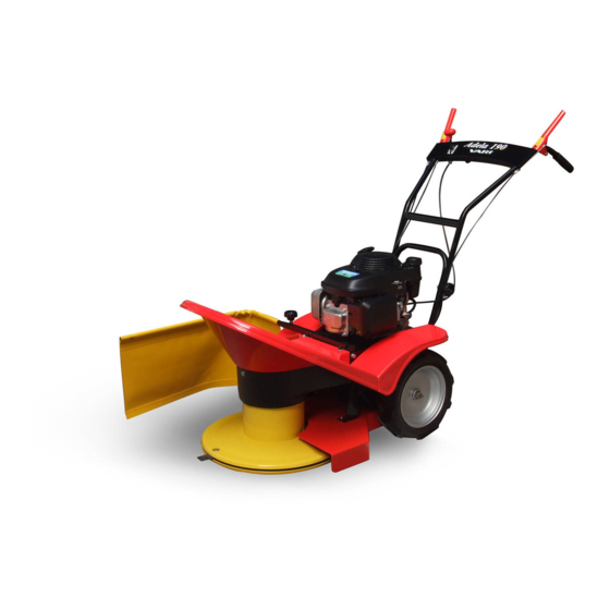
BDR-595 Adela Figure 1: Drum mower BDR-595 Adela Rear grip points (for steering, lifting or loading the machine) Cutting disk drive gear lever with brake Accelerator lever (engine speed setting) Machine travel gear clutch lever Starter grip Handlebars Engine Plastic rosebit to set... -
Page 10: Putting The Machine Into Operation
BDR-595 Adela 6. Bolt the upper casing (6) to the metal holder on the lower casing (14) by means of bolt M5x10 (15) and a large flat washer Ø5.5 mm (16). Mudguards (17) are to be screwed to the upper casing (6) by using bolts M6x16 (18), nuts M6 (19) and large flat washers Ø... -
Page 11: Starting The Cutting Disk
BDR-595 Adela 3. Let the new or cold engine running on choke for about 30 seconds (accelerator lever in the „CHOKE“ position), then move the accelerator lever into the position „MAX“. In this position let the engine running for about 30 seconds. - Page 12 BDR-595 Adela Figure 3: Handlebars and accelerator lever Clutch lever of the cutting disk drive and brake Accelerator lever (engine speed adjustment) Machine travel clutch lever Bowden cable of the cutting disk brake Right handlebar grip Bowden cable of the...
-
Page 13: Stopping The Machine
BDR-595 Adela STOP position of accelerator lever MIN (turtle) position of accelerator lever - engine stands still – engine runs idle MAX (hare) position of accelerator lever CHOKE position of accelerator lever (for – engine runs at maximum speed cold engine start only) – engine runs on choke 5.5 Stopping the machine. -
Page 14: Working With The Machine
BDR-595 Adela rotations; this is why it is advised to switch it off by pushing the lever into the STOP position as soon as possible!) 5.6 Working with the machine. 5.6.1 Working width of the machine. , Prior to the machine use, the sward must be cleared of solid bodies such as stones, wires, loose construction debris, etc., which could be flung or might otherwise... -
Page 15: Problems At Cutting
BDR-595 Adela 5.6.3 Problems at cutting. Choking of the cutting disk cover space with the cut material manifests as follows: a) Engine markedly losing speed but not stalling: machine travel to be switched off immediately (lever on the left handrail grip); drive on reverse gear just a bit with a simultaneous slight lifting of the machine front (by pushing down on the handlebar handrails). -
Page 16: Machine Lubrication
BDR-595 Adela 6.1 Machine lubrication. 6.1.1 Gear oil replacement and refilling. , When replacing oils, follow the basic hygienic principles, regulations and laws on environment protection. The gearing works in an oil bath. Oil volume should be checked once a month (oil plugs see Fig. -
Page 17: Engine Oil Replacement
BDR-595 Adela Figure 4: Oil plugs Plug to pour oil into the gearbox Plug to drain oil from the gearbox 6.1.2 Engine oil replacement. See the operating manual for engine. To drain oil, the machine should be either tilted to the side with the pour-in neck with oil gauge, or the engine should be dismounted from the machine (see Chapter 6.4, items a),b),d) ). -
Page 18: Tightening The Bolted Connections
BDR-595 Adela Figure 5: Lubrication points Figure 5.1: Rotary clutch lever Figure 5.3: Brake lever seating Figure 5.2: Tightening pulley arm pin 6.2 Tightening the bolted connections. Check the bolted connections for their proper tightening. Prior to each machine use, check the tightening of bolts fastening the blades in the upper disk as well as the tightening of bolts fastening the lower disk onto the flange. - Page 19 There is a “VARI“ stamp on the blade, which identifies the manufacturer and is at the same time a control mark indicating that the blade is an original spare part.
-
Page 20: V-Belt Replacement And Adjustment Of Tightening Pulley
BDR-595 Adela 6.4 V-belt replacement and adjustment of tightening pulley. V-belt should be replaced according to its wear (cracked sides, torn belt, sides worn out down to belt carrier fibres, belt “pulled“ out of shape) or after about 100 hours of operation at the maximum. - Page 21 BDR-595 Adela approx. 1.5 – 2.0 cm from the bottom of the tightening pulley (see Fig. 7) and the cable in the Bowden of the tension pulley must exhibit no slackness. In the case that the adjustment bolt is completely screwed out and it is necessary to tighten the V-belt, the spring on the cable can be hooked into the front hole on the arm of the tightening pulley (see Fig.
-
Page 22: Adjusting The Litz Wires Of Pulley, Brake And Machine Travel Gear Clutch
BDR-595 Adela 6.5 Adjusting the litz wires of pulley, brake and machine travel gear clutch. In order to guarantee low operating forces on levers which control the drive switching, it is advisable to lubricate the cables in Bowdens at least 2x during the season with some of oils available in atomiser (e.g. -
Page 23: Diagnostics Of Driving Problems
BDR-595 Adela 6.6 Diagnostics of driving problems. Problem Reason Remedial action Cutting disk does not Tightening pulley is not stressing Tightening pulley to be set by adjustment turn the belt properly bolt No. 2. (see Fig. 8) Litz wire is fallen out from... -
Page 24: Table Of Service Operations
BDR-595 Adela 6.7 Table of service operations. Operation During season After season Gearbox oil volume check 1x monthly yes,* Engine oil volume check prior to each machine use Engine air filter check prior to each machine use check Check of blades for fastening and... -
Page 25: Machine Storage
BDR-595 Adela c) Clean the wheel hub inside, wheel hub flange with balls and the free wheel from dirt and old grease. d) Fill the hub inside with new grease (e.g. for water pumps) lubricating at the same time also the flange with balls and free wheel surfaces. -
Page 26: Disposal Of Packaging And Machine After The End Of Service Life
6. All components should be ordered in the nearest service shop or at your dealer’s. In the case of any confusions concerning the spare parts or technical issues, the VARI a.s. commercial, customer-service or technical departments are prepared to answer all your inquiries. -
Page 27: List Of Components
BDR-595 Adela 9 List of components. -
Page 28: Machine Casing
BDR-595 Adela 9.1 Machine casing... - Page 29 BDR-595 Adela Machine casing Pos. Part Name Dimensions Drawing-Standard Ord. No. Pcs 1 Frame 22 9 1536 050 196 001 2 Screen holder 22 9 1856 005 169 016 4 Handle 22 9 8044 009 196 016 5 Upper cover...
-
Page 30: Handlebars
BDR-595 Adela 9.2 Handlebars... - Page 31 BDR-595 Adela Handlebars Pos. Part Name Dimensions Drawing-Standard Ord. No. Pcs 1 Handlebars weldment 22 9 8078 059 196 002 2 Control lever 32 0 8058 009 196 013 4 Clutch bowden cable 622 9 8074 044 196 515 5 Pulley bowden cable...
-
Page 32: Cutting Disc Drive
BDR-595 Adela 9.3 Cutting disc drive... - Page 33 BDR-595 Adela Cutting disc drive Pos. Part Name Dimensions Drawing-Standard Ord. No. Brake shoe 22 9 1664 024 189 014 Driven pulley 22 9 3325 012 189 004 Upper disc 22 9 5025 011 196 056 Brake cam 22 9 8032 048...
-
Page 34: Wheel Drive
BDR-595 Adela 9.4 Wheel drive... - Page 35 BDR-595 Adela Wheel drive Pos. Part Name Dimensions Drawing-Standard Ord. No. Pcs 1 Gearbox BDR-595 22 9 3282 052 196 014 2 Driving pulley 22 9 3325 032 196 046 3 Driven clutch element 32 0 3625 029B 196 045...
-
Page 36: Gearbox
BDR-595 Adela 9.5 Gearbox... - Page 37 BDR-595 Adela Gearbox Pos. Part Name Dimensions Drawing-Standard Ord. No. 1 Fork weldment 22 1 3330 013A 189 078 2 Complete lever 22 9 3330 017 196 022 3 Complete driving disc 22 9 3616 006 189 029 4 Worm...
-
Page 38: Letter Of Guarantee
Warranty period for the product and accessories supplied with the product is 24 months from the date of sale to the purchaser if not stated otherwise in the “Service Manual for VARI Machines and Systems Equipped with HONDA Engines“. Time from the enforcement of liability for defects to the date when the user was obliged to take over the thing after the end of repair is not included in the warranty period. - Page 39 BDR-595 Adela Warranty inspection 1 Warranty inspection 1 Date: ………………………………………Person in charge:………………………………………………… Machine model………………………… Serial No.:…………………………… Service shop stamp and signature Warranty inspection 2 Warranty inspection 2 Date:………………………………………Person in charge:………………………………………………… Machine model………………………… Serial No.:…………………………… Service shop stamp and signature Warranty service Warranty service Date of complaint delivery:………………………………………………………………………………………...
Need help?
Do you have a question about the BDR-595 Adela and is the answer not in the manual?
Questions and answers