
Related Manuals for AeroWorks 50cc EXTRA 300 ARF-QB


Summary of Contents for AeroWorks 50cc EXTRA 300 ARF-QB
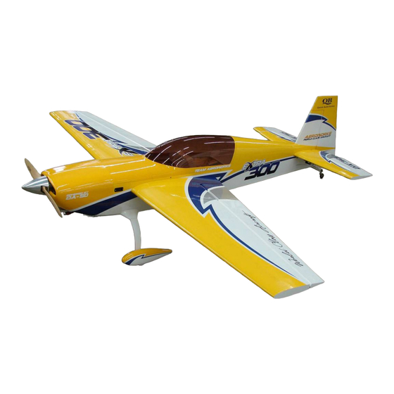
- Page 1 50cc EXTRA 300 ARF-QB (Quick Build) ASSEMBLY MANUAL AEROWORKS 4903 Nome Street, Denver, CO. 80239 - Phone 303-371-4222 - Fax 303-371-4320 E-mail - info@aero-works.net...
-
Page 2: Table Of Contents
TABLE OF CONTENTS Page Aeroworks Contact Information ………………………………………………………………. 3 Introduction ……………………………………………………………………………………... 4 Kit Contents……………………………………………………………………………………… 5 Items Needed To Complete ……………………………………………………………………... 8 Tightening and Re-shrinking the Covering ………………………………………………….. Ultracote™ Colors …………………………………………………………………………….. 10 Check Seams and Overlaps for Good Seal ……………………………………………………. 11 Checking Hinges For Proper Throw ……………………………………………………………... -
Page 3: Aeroworks Contact Information
Further, Aeroworks reserves the right to change or modify this warranty without notice. In that Aeroworks has no control over the final assembly or materials used for final as- sembly, No liability shall be assumed nor accepted for any damage resulting from the use by the user of the final user-assembled product. -
Page 4: Introduction
INTRODUCTION Your new 50cc EXTRA 300 ARF-QB is a highly aerobatic airplane. It is capable of both pre- cision and 3-D maneuvers. The aircraft builds easily, quickly, and precisely due to its state of the art CAD design, LASER cut technology, and high quality included hardware. We hope you enjoy building and flying your 50cc EXTRA 300 ARF-QB. -
Page 5: Kit Contents
KIT CONTENTS 40x14mm hex style bolts and (6) #6 bonded washers (1)Hatch cover for the landing gear installed by (2) 50cc Extra 300 ARF-QB T2.6x16mm PWA screws Materials List Canopy base—painted, with (4) 4-40 blind nuts in- stalled Basic Aircraft Parts (1) Tinted Canopy—glued on the canopy base and... - Page 6 (6) pin point hinges glued (1) AW Aluminum Tail Wheel Assembly – Medium (1) Aileron servo string installed Right Wing with Aileron – covered: Pre-drilled for the (1) 32mm o.d. Aluminum Tube for wing joint— mounting of the control horns Anodized Black (2) 8-32 blind nuts installed for the wing mounting.
- Page 7 (2) 6x70x160mm Foam for the Fuel Tanks (6) 8x450mm Nylon Ties for the fuel tank mounting (10) 3x150mm Small Nylon Ties for the fuel line (4) 356x12.5mm Velcro (1) Card Stock (8”x11”) for making the template for cutting of cowling (1) Pre-cut (hot air exit) Template for cutting out the bottom of the cowl (1) Paper Degree Meter for the Rudder...
-
Page 8: Items Needed To Complete
ITEMS NEEDED TO COMPLETE Hardware • Allen wrenches US and Metric. • Dremel cutting disc and sanding drum tool • Electric drill and selection of bits • Razor saw • Flat head screwdriver • Hobby heat gun • Hobby iron and covering sock •... -
Page 9: Tightening And Re-Shrinking The Covering
TIGHTENING AND RE-SHRINKING THE COVERING 1. Open your kit slowly and take care not to dam- 3. If bubbles persist, use a small pin to punch holes age any parts of the kit. Remove all parts from in the bubble to relieve trapped air and reheat. their plastic protective covers for inspection. -
Page 10: Ultracote™ Colors
Ultracote™ Colors 1. Your model is covered with Ultracote™ covering. In case of repairs, the colors are: Yellow/Silver/Blue Scheme Pearl Blue #845 Silver #881 Cub Yellow #884 White #870 Red/White/Black Scheme Black #866 Silver #881 True Red #866 White #870... -
Page 11: Check Seams And Overlaps For Good Seal
It is the responsibility of the purchaser / operator to check the covering seams and overlaps for security and a good seal. Aeroworks is not responsible for failure of covering seams or overlaps during flight. Note: If covering continues to lift apply a small amount of thin CA underneath the covering. -
Page 12: Checking Hinges For Proper Throw
CHECKING HINGES FOR PROPER THROW If the elevator hinges are tight follow the IMPORTANT same process as described for the wings. If control surfaces will not throw to full deflec- tion it may be necessary using a heat gun to Note: Once these steps have been completed apply heat to the knuckle of each hinge. -
Page 13: Wing Assembly
WING ASSEMBLY 3. Attach the 6” extension to the servo lead and Aileron Servo Installation secure with Aeroworks Safety Clip. Ensure the connectors will not come apart from vibration or 1. The ailerons have been pre-hinged and glued to light tension. - Page 14 5. Draw the servo extension through the wing and 7. Install servo with servo mounting screws. pull through the wing root rib. Note: Taping servo lead to the inside of the wing panel will help to prevent lead from dropping back inside of wing panel during transportation 6.
- Page 15 2. Assemble the pushrod and control horn assem- 4. Place the control horns over the predrilled bly as shown. The ball link goes between the mounting holes. left and right sides of the control horn sides and is secured with a nylon lock nut. Start with the center hole in the control horn.
- Page 16 6. Securely fasten the control horn to the aileron 8. Use the supplied adjustment wrench to adjust the with six wood screws. pushrod as shown below. 9. Use the opposite end of the adjustment wrench 7. Plug servo and battery into the receiver and turn to tighten the pushrod jam nuts against the ball radio on.
- Page 17 10. Ensure the servo does not bind at either end point at full deflection. A 1” servo arm is rec- ommended for best results. A 1 1/4” servo arm is required for full deflection of the aileron bevel. 11. Repeat all the above steps for the other wing.
-
Page 18: Stab And Elevator Assembly
STAB AND ELEVATOR ASSEMBLY 4. Install servo with servo mounting screws. Elevator Servo Installation 1. The elevators have been pre-hinged and glued to the stabs and are ready for flight. No other steps are necessary for hinging. Clear covering has been provided for sealing of the hinge gaps if desired. - Page 19 2. Assemble the pushrod and control horn assem- 4. Place the control horns over the predrilled bly as shown. The ball link goes between the mounting holes. left and right sides of the control horn sides and is secured with a nylon lock nut. Start with the center hole in the control horn.
- Page 20 6. Mount the control horn using six wood screws. 8. Use the supplied adjustment wrench to adjust the pushrod as shown below. 7. Plug servo and battery into the receiver and turn 9. Use the opposite end of the adjustment wrench radio on.
- Page 21 10. Finished elevator servo installation shown be- low. Repeat steps for other stab/elevator assembly...
-
Page 22: Rudder And Pull-Pull Cable Assembly
RUDDER AND PULL – PULL CABLE ASSEMBLY 3. Mix epoxy in mixing cup and use a tapered stick Rudder Installation to apply the epoxy inside the pre-drilled holes in the trailing edge of the fin. Apply epoxy to one 1. Gather the rudder, five hinges, rubbing alcohol, side of each hinge and insert the hinge com- petroleum jelly and epoxy materials as shown. -
Page 23: Servo Installation
5. Mix epoxy in mixing cup and use a tapered stick 7. Ensure there is no gap between fin and rudder. to apply the epoxy inside the pre-drilled holes in Allow epoxy to fully cure. Check you have full the leading edge of the rudder. Apply epoxy to rudder deflection before epoxy fully cures. - Page 24 2. Gather the rudder control horn parts as shown 4. Place the control horns over the predrilled below. (2) ball link assemblies, (2) left and (2) mounting holes. right side control horns. Assemble the ball links between the control horns as shown. Secure with nylon lock nut.
- Page 25 6. Mount rudder control horns using six wood 9. Install the rudder servo in the servo cutout with screws. the output shaft to the front. Note: Remove balsa stick holding the elevator pull 7. Repeat the above steps for mounting the other strings at this time.
- Page 26 11. Pull the rudder cables from rear of fuse to the 13. Thread cable through brass swage tube. rudder servo tray. Note: Cables run parallel down fuse and do not cross each other. 12. Using an X-ACTO knife clean away any burrs 14.
- Page 27 15. Loop the cable back through the brass swage 17. Cut off excess cable as shown tube and pull tight. 16. Crimp the brass swage tube with a crimping tool 18. A drop of thin CA may be applied to the swage or pliers.
- Page 28 19. Attach ball links to the rudder servo arm and 21. Tape the rudder balance tab to the top leading then attach the servo arm to the rudder servo as edge of the vertical fin in the neutral position as shown.
-
Page 29: Tail Wheel Installation
23. Follow the same steps for the opposite side of 2. Align rudder tiller steering arm with pre drilled the rudder as shown below. Rudder pull pull as- mounting holes at bottom of rudder. sembly is now complete. 3. Apply a drop of thick CA to the tiller arm Tail Wheel Installation mounting screws before inserting in the pre- drilled holes. - Page 30 4. Mount the tail wheel steering tiller using two 6. Place a drop of thick CA on tail wheel strut wood screws. mounting screws before inserting in the pre- drilled mounting holes on the bottom rear of the fuse. 5. Place the tail wheel leaf spring on top of the tail 7.
- Page 31 8. Attach the steering spring to the rudder tiller. 10. With spring centered between tiller arms and tail Center the spring between both tail wheel and wheel centered, bend spring wire through tail steering tillers. wheel steering tiller. 9. Use pliers to twist spring end closed around the 11.
- Page 32 12. Repeat spring installation for other side. 13. Bottom view of completed tail wheel installa- tion.
-
Page 33: Main Landing Gear, Gear Cuffs, And Wheel Pants Assembly
MAIN LANDING GEAR - GEAR CUFF AND WHEEL PANT ASSEMBLY 3. Align mounting holes of main landing gear with Main Landing Gear Installation pre drilled mounting holes in fuselage mounting plate. 1. Gather the landing gear parts as shown below: •... - Page 34 5. Bolt landing gear strut to fuse with (4) 8-32 bolts 7. Gather the landing gear cuffs, mounting bolts and washers. Ensure tapered edge of the gear and bonded washers. strut is facing toward the rear. Note: There is a right and left gear cuff. 6.
- Page 35 9. Use the (2) 4-40 mounting bolts and (2) bonded 12. Align the flat sides of the axle bolt vertical and washers to secure the gear cuffs to the landing snug the lock nut against the landing gear strut. gear. 10.
- Page 36 14. Tighten the lock nut against the landing gear 16. Install the wheel and outer wheel collar. Use strut to secure axle. blue Loctite on the wheel collar set screw before final tightening. 15. Install the inner wheel collar on the axle. Use a 17.
- Page 37 18. Repeat above steps for other wheel and wheel pant. 19. Final landing gear installation shown below.
-
Page 38: Engine Installation
ENGINE INSTALLATION 3. Locate the laser cut engine mounting template Engine Installation for either the DA-50 or 3W-50. If other engines 1. The 50cc Extra 300 will accept a wide range of are used the Universal template may be modified engine types. - Page 39 5. Mark the location of the engine mounting holes 7. Remove engine box top hatch cover. on template. 6. Use a 1/4 drill bit to drill the engine mounting 8. Align mounting template with firewall and tape holes. Template is now ready for use. in place.
- Page 40 9. Use a 1/4 bit to drill the engine mounting holes in 11. Using mounting bolts and flat fender washers firewall. mount engine to firewall. Tighten the bolts evenly to prevent crushing of the firewall. 10. Use blue loctite to secure the engine mounting 12.
- Page 41 13. Attach the muffler to the motor at this time. Note: Muffler will be removed during cowl installa- tion. It may be left off at this time in order to aid in cowl installation.
-
Page 42: Canister Installation
CANISTER INSTALLATION Canister Installation 2. Use a hobby knife to remove the covering around the hot air exit holes. Gather the canister muffler parts as shown: Shown: (1) KS 86 Canister (Rear Exit) Note: Take care not to remove the covering from the (1) 25mm Drop Double Bend flex header tuned pipe hatch cover. - Page 43 4. Canister mounting bracket location shown be- 6. Use 30 Minute epoxy to secure the canister low. mount as shown. 5. Test fit canister mount in the fuse. If necessary 7. Reinstall the canister mount in the fuse. Allow sand canister mount to achieve proper fit. epoxy to fully cure before moving on to the next step.
- Page 44 10. Slide the canister into the canister tunnel as Canister mount viewed from front as shown be- shown below. low. 9. Assemble the canister to the header with the Tef- 11. Secure the header in place using the mounting lon coupler and clamps in accordance with bolts and gasket provided with your engine.
- Page 45 12. Finished canister installation shown below. 13. Reinstall canister hatch as shown below. Canis- ter installation is now complete.
-
Page 46: Tuned Pipe Installation
Tuned Pipe Installation Tuned Pipe Installation 2. Use a hobby knife to remove the covering around the hot air exit holes as shown. Gather the tuned pipe parts as shown: Shown: (1) MTW RE2 Tuned Pipe (1) 25mm Drop Double Bend Flex Header (1) Teflon Coupler (2) Mounting Clamps... - Page 47 4. Tuned pipe mounting bracket location shown 6. Use 30 Minute epoxy to secure the pipe mount below. as shown. 5. Test fit pipe mount in the fuse. If necessary sand 7. Reinstall the pipe mount in the fuse. Allow ep- pipe mount to achieve proper fit.
- Page 48 10. Assemble the tuned pipe to the header with the Pipe mount viewed from front as shown below. Teflon coupler and clamps in accordance with manufactures instructions. 9. Remove engine to allow easier tuned pipe instal- 11. Slide the tuned pipe into the pipe tunnel as lation.
- Page 49 12. Reinstall engine as shown below. 15. Reinstall pipe hatch as shown below. Pipe in- stallation is now complete. 13. Secure the header in place using the mounting bolts and gasket provided with your engine. Use blue Loctite to secure the bolts. 14.
-
Page 50: Throttle/Choke Servo Installation
3. Assemble ball link to threaded end of pushrod. Throttle Servo and Choke Installation Gather the left and right plywood throttle and Note: Thread ball link half way onto pushrod to choke servo mounting trays, the throttle and allow for proper adjustment during final choke servos, servo arms and pushrod parts as installation. - Page 51 5. Assemble brass threaded coupler to 4-40 ball 7. Assemble servo arm to servo at 90 degrees to link and ball link and brass spacer to the servo servo. Align throttle servo with throttle pushrod arm as shown below. and mark servo mounting location. Ensure the throttle pushrod will line up with the servo out- put arm with no binding.
- Page 52 9. Apply 5 minute epoxy to the side of the servo 11. With servo arm still 90 degrees to servo and mount that will be in contact with the engine box throttle arm of carburetor in the center or half side.
- Page 53 13. Gather the soldering tools as shown below. 15. Solder the threaded brass coupler to the end of the throttle pushrod. Note: For best results we recommend a high quality Silver Solder like “Sta-Brite” silver solder. 14. Lightly sand end of pushrod for best bond. 16.
- Page 54 17. If installing a choke servo use the provided 19. We recommend installing the carburetor choke mounting tray and hardware shown below. Fol- pushrod as shown. Use nylon ties to provide lowing same installation steps used for installing support and holding friction for the choke push- throttle servo install choke servo.
-
Page 55: Ignition Installation
IGNITION INSTALLATION 1. Gather the ignition module, battery, switch, 3. Use a 1/8” bit to drill the ignition module regulator and installation parts as shown below. mounting holes. 2. Position the ignition module on the side of the 4. Thread nylon tie through mounting holes. engine mounting box and mark the location of the nylon tie holes as shown. - Page 56 5. Roll the supplied foam rubber to make a 4 layer 7. Connect ignition module to pickup line of en- pad as shown. Make the pad slightly larger than gine. Secure with Safety Clip, safety wire, tape the ignition module. or other method.
- Page 57 9. Mount ignition battery on opposite engine box 11. Mount switch in accordance with the switch side with nylon tie and foam padding. manufacturers instructions and hardware. 10. Switch mounting location is at builders discre- 12. Mount ignition regulator as desired. Secure all tion.
-
Page 58: Fuel Tank Assembly And Installation
FUEL TANK ASSEMBLY AND INSTALLATION 3. Assemble the fuel pick up line, rubber stopper Fuel Tank Assembly and metal end caps. As shown below. 1. Gather the fuel tank parts as shown below. • Fuel tank • Hardware • Brass barbs •... - Page 59 5. Final assembly of rubber fuel stopper with fuel 7. Install the fuel tubing and clunk. Secure the fuel pick up tube shown below. tubing with nylon ties to the pick-up tube and clunk. 6. Install air vent tube into rubber stopper and bend 8.
-
Page 60: Fuel Tank Installation
“T”, fuel filter in the fuel line to the carburetor. filler dot, fuel filter and nylon ties. Note: The fuel “T”, and fuel filter are not supplied, but are available through Aeroworks. Filter Carb Fill... - Page 61 4. Use small nylon ties to secure fuel line. 6. Thread nylon ties under tank mounting plate and center in position. Note: Gasoline will cause the fuel line to expand over time. Always secure fuel lines with nylon ties to prevent them from pulling off during flight.
- Page 62 8. Install the tank. Run the fuel pick up line to the 10. Mark location of fuel filler dot. engine. Secure the tank with the two long nylon ties trim away any excess nylon tie as shown. 9. Gather the fuel filler dot and drill bits as shown 11.
- Page 63 12. Use thick CA to secure fuel dot in fuse. 14. Secure fuel pick up line to engine carburetor with small nylon tie. 13. Feed filler line through dot and plug line into 15. Route the vent line on top of the fuel tank and filler plug as shown.
- Page 64 16. Feed vent line tubing through bottom of fuse. Cut off excess fuel line. Note: Place a zip tie around the vent line as shown. Be careful not to tighten the zip tie to the point of closing the vent line. This will pre- vent the vent line from falling back inside the fuse and flooding the airplane with gas during fueling.
-
Page 65: Radio Installation
RADIO INSTALLATION 1. Gather the radio components as shown below. 3. Install regulator in accordance with manufactur- Battery, Switch, Regulator if used, receiver, ers recommended installations. foam rubber and Velcro one wrap straps. 2. Mount radio switch in accordance with the 4. - Page 66 5. Install receiver using foam padding and Velcro 7. Place tape on the antenna and tube, this will one wrap strap as shown. keep the antenna from backing out of the tube. 6. Install the receiver antenna in the pre-mounted 8.
- Page 67 9. Typical radio installation shown for heavier en- gine selections. Note: If models CG is tail heavy move batteries forward. If models CG is nose heavy move batteries to the rear. 10. Reinstall engine box top hatch cover.
-
Page 68: Cowl Installation
COWL INSTALLATION 1. Remove muffler as shown below. 3. Tape the provided template material to the bot- tom of the fuse as shown below. 2. Gather the materials as shown below. Template 4. Use a T-Pin to mark the location of the bottom material, hobby knife, ruler, tape, marker and cowl mounting bolts onto the template. - Page 69 5. Enlarge mounting holes using a hobby knife as 7. Mark “Cowl Side” on the top side of the tem- shown. plate. It is very important that the template does not change position when attached to the cowl. 8. Trace around the head of the engine being care- 6.
- Page 70 9. Use a hobby knife to cut out the engine cylinder 11. Using cowl mounting bolts align template with exit opening as shown. bottom of cowl. Use a felt tip marker to transfer the template cutout pattern to the cowl and mark cut location.
- Page 71 13. Install the cowl and check that everything fits Cutting Cowl For Muffler Installation correctly and nothing rubs against cowl. If needed enlarge the cutouts and test fit again until 1. Gather the pitts style muffler as shown below. everything fits correctly. If using canister or tuned pipe locate the pre-cut 2.
- Page 72 4. It will be necessary to turn the cowling as shown in order to clear the muffler for installation. 5. Mount cowl to the fuse using (4) 4-40x16mm button style hex head bolts (4)#6 bonded washers...
-
Page 73: Preflight Preparation
1. Gather (4) 8-32 wing mounting bolts, (4) #8 rub- 3. Attach the 6” extension to the servo lead and ber backed washers and (4) hairpins for prepara- secure with Aeroworks Safety Clip. Ensure the tion of mounting the wings. connectors will not come apart from vibration or light tension. - Page 74 5. Gather (4) 4-40 stab mounting bolts and (4) #6 7. Gather (2) 4-40, (2) 6-32 cowl mounting bolts small rubber backed washers. and (4) #6 small rubber backed washers. 6. Slide the stab tubes in the fuse stab tube sleeves. 8.
- Page 75 9. Gather the (4) 4-40 hatch mounting bolts and (4) #6 small rubber backed washers. Note: It is highly recommended you apply thin CA glue to the front hold down dowels. This is a High vibration area and can loosen the front dowels. Always check the front dowels are secure before each flying session Us thin CA to...
-
Page 76: Decal Installation
DECAL INSTALLATION 3. Placement of optional decal package shown, in- Decal installation cluded decals will differ. 1. Decals supplied with the kit may vary from the photos below. Decal installation instructions are for reference purposes only. Gather supplied decals, transfer tape, ruler, scis- sors, hobby knife, plastic squeegee or credit card, Windex or Application fluid like Rapid Tac. - Page 77 4. Using rubbing alcohol or glass cleaner. Clean all 6. Remove backing from decal sheet. areas before any decal installation. Note: Decals and model shown in following steps may very from your model. Decal installation will be similar 5. Tighten all covering prior to any decal installation. 7.
- Page 78 8. Spray back side of decal with application fluid, 10. Using a plastic squeegee or credit card. Spread Windex or soapy water solution. decal smooth and remove all excess application fluid. Let decal set until dry enough to be able to remove transfer tape with out removing decal.
- Page 79 12. Finished decal installation. Work slowly and carefully and you will be rewarded with a beautifully finished model.
-
Page 80: Center Of Gravity (C.g.) / Control Throws
4” location. Control Throws 1. The amount of control throw should be adjusted 2. Balance the 50cc EXTRA 300 ARF-QB without using mechanical means as much as possible and fuel in the tank with the batteries installed and then electronically with the radio. - Page 81 3. Use the widest part of the elevator as shown to 5. Slide the throw meter under the rudder boost tab. measure the elevator throw in inches. 4. Gather the Rudder Throw Meter (Supplied) and 6. Center the throw meter on the rudder using the scotch tape.
- Page 82 7. Secure the tabs to the fin using scotch tape. Use the supplied flight control deflection meter . Prop up the to measure the throws in degrees tail of the aircraft until the fuselage is paral- lel to the table top. 10.
-
Page 83: Control Throw Deflection Table
Control Throw Deflection Table Preflight Checks Low Rate High Rate Center of Gravity: Check CG is set properly. Aileron 1 3/4” or 18˚ up 2 1/2” or 25˚ up Engine: The engine should run smoothly at all 1 3/4” or 18˚ down 2 1/2” or 25˚ down throttle settings with smooth transition from idle to full throttle without stalling or hesita- Rudder... - Page 84 Aerobatics The 50cc EXTRA 300 ARF-QB is capable of any aerobatic maneuver. After you gain some confi- dence and little experience flying the airplane you can cut loose and perform any maneuver you can think of. Here is a list of some of the more popular aerobatic and 3D maneuvers you can try: •...
- Page 85 50 cc EXTRA 300 ARF-QB NOTES ___________________________________________________________________________ ___________________________________________________________________________ ___________________________________________________________________________ ___________________________________________________________________________ ___________________________________________________________________________ ___________________________________________________________________________ ___________________________________________________________________________ ___________________________________________________________________________ ___________________________________________________________________________ ___________________________________________________________________________ ___________________________________________________________________________ ___________________________________________________________________________ ___________________________________________________________________________ ___________________________________________________________________________ ___________________________________________________________________________ ___________________________________________________________________________ ___________________________________________________________________________ ___________________________________________________________________________ ___________________________________________________________________________ ___________________________________________________________________________ __________________________________________________________________________...
Need help?
Do you have a question about the 50cc EXTRA 300 ARF-QB and is the answer not in the manual?
Questions and answers