
Related Manuals for AeroWorks 60-90 EXTRA 260 ARF-QB


Summary of Contents for AeroWorks 60-90 EXTRA 260 ARF-QB
- Page 1 60-90 EXTRA 260 ARF-QB (Quick Build) ASSEMBLY MANUAL AEROWORKS 4903 Nome Street, Denver, CO. 80239 - Phone 303-371-4222 - Fax 303-371-4320 E-mail - info@aero-works.net...
-
Page 2: Table Of Contents
TABLE OF CONTENTS Page Aeroworks Contact Information ………………………………………………………………. 3 Introduction ……………………………………………………………………………………... 4 Kit Contents……………………………………………………………………………………… 5 Items Needed To Complete ……………………………………………………………………... 7 Tightening and Re-shrinking the Covering ………………………………………………….. Check Seams and Overlaps for Good Seal ……………………………………………………. 9 Wing Assembly………………………………………………………………….……………….. 10 Stab and Elevator Assembly……………………………………………………………………. 14 Rudder and Pull-Pull Cable Assembly …………………………………………………………... -
Page 3: Aeroworks Contact Information
Further, Aeroworks reserves the right to change or modify this warranty without notice. In that Aeroworks has no control over the final assembly or materials used for final as- sembly, No liability shall be assumed nor accepted for any damage resulting from the use by the user of the final user-assembled product. -
Page 4: Introduction
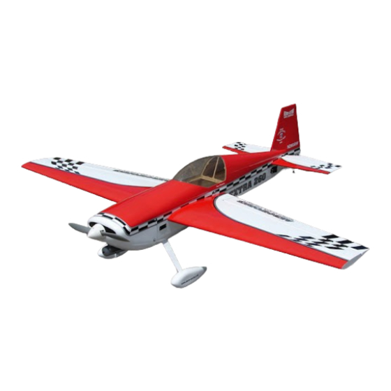
INTRODUCTION Your new 60-90 EXTRA 260 ARF-QB is a highly aerobatic airplane. It is capable of both precision and 3-D maneuvers. The aircraft builds easily, quickly, and precisely due to its state of the art CAD design, LASER cut technology, and high quality included hardware. We hope you enjoy building and flying your 60-90 EXTRA 260 ARF-QB. -
Page 5: Material List
KIT CONTENTS (4) 3mm split lock washers for the mounting of the MATERIAL LIST canopy 60-90 size Extra 260 (1) 3.5(o.d.) x600mm Antenna tube installed (2) 3.5(o.d.) x70mm pull-pull exit tube installed BASIC AIRCRAFT PARTS: Left Wing with Aileron – covered: Pre-drilled for the mounting of the control horns (1) 6-32 blind nut installed for the wing mounting. - Page 6 (2) 2.1x22mm threaded rod with nylon clevises Horizontal Stabilizer with elevator assembly with (6) (1) 1.8x300mm push rod with Z bend on one end CA hinges (not glued)---covered Elevators Pre-drilled (1) 3.5mm o.d. x300mm push rod sleeve for the mounting of the control horns (1) Easy Connector (2) Plywood plastic tube holder Rudder with (4) CA hinges (not glued) –...
-
Page 7: Items Needed To Complete
ITEMS NEEDED TO COMPLETE Hardware • Allen wrenches US and Metric. • Dremel cutting disc and sanding drum tool • Electric drill and selection of bits • Razor saw • Flat head screwdriver • Hobby heat gun • Hobby iron and covering sock •... -
Page 8: Tightening And Re-Shrinking The Covering
TIGHTENING AND RE-SHRINKING THE COVERING 1. Open your kit slowly and take care not to dam- 3. If bubbles persist, use a small pin to punch holes age any parts of the kit. Remove all parts from in the bubble to relieve trapped air and reheat. their plastic protective covers for inspection. -
Page 9: Check Seams And Overlaps For Good Seal
Aeroworks is not re- sealed securely. This is especially important at the sponsible for failure of covering seams or over- leading edges of the wings and stabs. -
Page 10: Aileron Servo Installation
WING ASSEMBLY 3. Use a straight edge to make sure that the aileron Aileron/Servo Installation sits flush with the wing-tip. The ailerons and wings come pre-hinged but are not glued. The builder must glue the hinges in place using thin CA. 1. -
Page 11: Pushrod / Control Horn Installation
5. Using preinstalled draw string draw the servo 8. Install the servo using the hardware supplied by extension through the wing and pull through the the servo manufacturer. wing root rib. Note: Taping servo lead to the inside of the wing panel will help to pre- vent lead from drop- ping back inside of... - Page 12 2. Place the control horns over the predrilled 4. Thread the two mounting bolts into the control mounting holes. horn back plate on top of the aileron. Be careful not to over tighten as this could crush the sheet- ing. 3.
- Page 13 6. Locate the 2 aileron pushrods, 2 metal R/C links 8. Install the pushrod onto the nylon control horn and 2 nylon keepers. using the supplied R/C Link. Center all servos using the radio, leave the radio on until you have clearly marked the pushrod.
-
Page 14: Stab And Elevator Assembly
10. Final servo installation shown below. Be sure to 2. Install the wing and check the alignment of the use a piece of fuel tubing over the clevis to keep stab to the wing. it secure. 3. Ensure the ailerons are centered with the wing, it Stab/Elevator Installation may be necessary to tape them in place. - Page 15 4. Use a pen to lightly mark the stabs position in 6. Mix 30 Minute Epoxy and brush onto the ex- relation to the fuse on both top and bottom. posed wood in the center of the stab. Make sure to use epoxy on both top and bottom.
-
Page 16: Servo And Pushrod Installation
Us a 1/16” drill bit to drill the 4 1. Gather the elevator servo and 12” extension. It is servo mounting screw holes. recommended that an Aeroworks safety clip is used on the connecter to keep the extension con- nected to the servo. -
Page 17: Rudder And Pull-Pull Cable Assembly
4. Install the servo using the hardware supplied by 6. Finished elevator servo and pushrod assembly the servo manufacturer. shown below. 5. Install the nylon control horn using the same Rudder and Pull-Pull installation method as described on the wings. 1. - Page 18 2. Use 3-4 drops of Thin CA on each side of the 4. Gather the rudder servo and a 2” double out put rudder to securely glue each hinge to the Verti- arm, this will give you the best geometry and the cal fin.
- Page 19 6. Place a drop of Thick CA on the nuts to prevent 8. Tape the rudder balance tab to the top leading them from loosening in flight. edge of the vertical fin in the neutral position as shown. This ensures the rudder is straight when the cables are attached.
- Page 20 10. Pull the rudder cables from rear of fuse to the 12. Install the clevises on the rudder servo arm. rudder servo tray. Note: Cables run parallel down fuse and do not cross each other. 11. Assemble the pull-pull clevis and threaded cou- 13.
-
Page 21: Main Landing Gear, Wheel Pants And Tail Wheel Assembly
MAIN LANDING GEAR/ TAIL WHEEL/ WHEEL PANTS ASSEMBLY 14. Assemble and install the clevises onto the rudder control horns. 1. Gather the landing gear parts as shown below. Landing gear strut, 3 6-32 mounting bolts, 3 flat Finished pull-pull assembly shown below. washers, 3 lock washers, 2 wheel pants, 4 4-40 mounting bolts, 2 wheels, 2 axles assemblies, 4 wheel collars, tail wheel strut, 3 tail wheel... - Page 22 3. Install the rear wheel collar about 2mm away 5. Install the landing gear with the straight edge from the axle back plate, install the wheel and towards the front and the tapered edge towards then install the final collar. the rear.
- Page 23 7. Main landing gear installation is now complete. 9. Apply a drop of thick CA to the tiller arm mounting screws before inserting in the pre- drilled holes. 8. Align rudder tiller steering arm with pre drilled 10. Mount the tail wheel steering tiller using two mounting holes at bottom of rudder.
-
Page 24: Cowl Preparation For Glow Engine Installation
11. Install the tail wheel using three wood screws. COWL PREPERATION FOR GLOW Use thick CA to secure the mounting screws. ENGINE INSTALLATION Note: If Installing an electric motor go to page 35 1. Align cowl to fuse and bolt in place. Mark the location of the air exit from the fuse onto the cowling. -
Page 25: Stroke Engine And Throttle Servo Installation
ENGINE AND THROTTLE SERVO INSTALLATION 2. Gather the glow engine of your choice, 8 6-32 4. Set the engine in between the left and right bolts 8 3.5mm flat washers, 4 3.5mm split lock mounting rails. It may be necessary to clamp the washers and 4 6-32 lock nuts. - Page 26 6. Mark the position of the engine mounting holes 8. Use 4 6-32 bolts, 4 flat washers, and 4 6-32 lock on the engine mount. Mark the center of each nuts to install the engine to the mount. engine mounting hole with a center marking tool or beveled pencil or pen.
- Page 27 10. Trace the size and location of the throttle push- 12. Reinstall the engine mounts using a small rod guide tube onto the firewall. amount of blue loctite, this will keep the bolts in place. Note: Insure throttle pushrod is lined up with throttle arm of the carb.
- Page 28 3. Install the throttle pushrod guide tube into the Throttle servo installation for 2 stroke hole drilled in a previous step and secure in engine place with thick CA. Slide the pushrod through the guide tube and install the threaded rod with 1.
-
Page 29: Stroke Engine And Throttle Servo Installation
5. Install the precut foam block at the rear of the 7. Place the 6mm x 130mm x 60mm foam pad firewall. Glue or double sided tape may be used onto the tank floor. It will be necessary to cut to secure the foam block to the tank floor. - Page 30 2. Install the engine using the same method as the 2 4. Use a drill bit to drill the hole for the throttle stroke installation. The correct distance from the pushrod guide tube firewall to the thrust washer is 4 3/4”. 5.
- Page 31 6. Install the pushrod guide tube and throttle push- 8. Secure the pushrod to the side of the fuse with rod onto the engine using the pre-bent Z-bend. the included plywood guides. 7. Attach the pushrod to the servo using the sup- 9.
- Page 32 10. Route the included zip ties through the precut tank mounting slots. 11. Place the 6mm x 130mm x 60mm foam pad onto the tank floor.
-
Page 33: Fuel Tank Assembly And Installation
. This will make it easier to reference after completely drain the tank. installation. Note: Fuel filler dot not included but available through Aeroworks. Vent Carburetor Fill Line 2. Assemble the stopper as shown below. Use Zip 4. - Page 34 5. Install the fuel filler dot (not supplied) higher than the tank to keep the fuel from draining out during refueling. 6. Install the fuel tank using the nylon tie installed earlier. 7. Finished tank installation shown below.
-
Page 35: Electric Motor And Battery Installation
Note: Use a covering iron to seal the cover- ing before removing any material. Note: Motor mount available from Aeroworks 4. Use 30 Minute Epoxy to assemble the engine 2. Final hot air exit holes shown below. It is recom- mounting block. - Page 36 7. Install the 6-32 blind nuts into the back of the the skyshark lightning 50 power package elec- motor mount. tric package available through Aeroworks, other installations may differ slightly. Gather the motor mount, Electric motor, 5cell 5000mah battery, 60A ESC, 3A BEC 6.
- Page 37 Glue the supplied spacer plate to the back side of 11. Align the center marks made in the previous the motor mount. steps with the laser etched motor thrust marks on the firewall. Make sure the mount is aligned properly and trace all the way around the mount.
- Page 38 13. Drill the 4 mounting holes using a 5-32 drill bit. 15. Drill the 4 mounting holes using a 5-32 drill bit. Install the 4 6-32 blind nuts using the same method as described steps 7 and 8 14. Clamp the mounting block to the firewall and 16.
- Page 39 17. Gather the 2 supplied air inlets. Use 200 grit 19. Finished air inlet installation shown below. sand paper to lightly scuff the gluing surface for a stronger bond. 20. Use the motor mounting bolts (not supplied) to 18. Use 30 minute epoxy to glue the air inlets in mount the motor.
- Page 40 21. Check the distance from the firewall to the prop 23. Use adhesive backed Velcro (not supplied) to adaptor, the correct distance is 4 3/4”. secure the battery. Use 3 pieces of the hook side measuring 37mm x 20mm mounted to the bat- tery and a large piece measuring 40mm x 220mm on the battery tray floor.
- Page 41 25. Final electric installation shown below.
-
Page 42: Cowl Installation
Cowl Installation 1. Gather the materials as shown below. Template 3. Flip the airplane over and trace the muffler material, hobby knife, ruler, tape, marker and shape onto the template, and leave 1” of space pencil. between the cutout and the muffler. 4. - Page 43 5. Use a Dremel tool to cut out the cowl. Cut a strip of the template long enough to reach the glow plug on the engine. Tape this strip to the side of the fuse and mark the location of the plug.
- Page 44 10. Finished cowl installation shown below.
-
Page 45: Radio Installation
Radio Installation 1. Gather the receiver, receiver battery, switch, 6” 4. Final switch installation shown below. extension 2 nylon ties, foam pad, and Velcro One Wrap Strap as shown below. 5. Route the included nylon ties into the precut 2. Mark the switch location on the fuse as shown making sure that it does not interfere with the mounting holes as shown below for the re- wing location. - Page 46 6. Mount the receiver battery with nylon tie and 8. Install the receiver antenna in the pre-mounted foam padding. antenna tube. Push the antenna into the antenna tube, be sure that the antenna is all the way into the tube. Note: Placing baby powder on the antenna will aid in sliding it through the tube.
-
Page 47: Decal Installation
Decal installation 1. Decals supplied with the kit may vary from the photos below. Decal installation instructions are for reference purposes only. Gather supplied decals, transfer tape, ruler, scis- sors, hobby knife, plastic squeegee or credit card, Windex or Application fluid like Rapid Tac. - Page 48 3. Use a straight edge and a hobby knife to separate 5. Peel the backing from the transfer tape. the decals from the rest of the decal sheet. 4. Cut a strip of transfer tape the same size as the 6.
- Page 49 7. Firmly press the transfer tape onto the decal. 9. Spray the area with application fluid before in- stalling the decal to allow a longer working time and aid in positioning the decal. 10. Apply the decal onto the surface. 8.
- Page 50 11. Using a plastic squeegee or credit card. Spread 13. Finished decal installation. Work slowly and decal smooth and remove all excess application carefully and you will be rewarded with a fluid. Let decal set until dry enough to be able to beautifully finished model.
-
Page 51: Preflight Preparation
PRE-FLIGHT PREPARATION 1. Slide the wing tube in the fuse wing tube sleeve. 3. Slide the rubber backed washers on the hatch Slide the wings on the wing tube and plug in the mounting bolts and insert bolts through the hatch aileron servo connectors. -
Page 52: Center Of Gravity - Control Throws
The control 2. Balance the .60-90 EXTRA 260 ARF-QB with- throws are shown in degrees and inches of de- out fuel in the tank with the batteries installed flection measured at the widest point of the con- and ready to fly. - Page 53 3. Use the widest part of the elevator as shown to 5. Slide the throw meter under the rudder boost tab. measure the elevator throw in inches. Use scotch tape to secure the throw meter to the rudder. 4. Gather the Rudder Throw Meter (Supplied) and 6.
-
Page 54: Control Throw Deflection Table
Low Rate High Rate table top. Deflection meter is available from Aeroworks. Aileron 1 ” or 16˚ up 1 1/2” or 25˚ up 1 ” or 16˚ down 1 1/2”... -
Page 55: Preflight Checks
Preflight Checks Aerobatics Center of Gravity: Check CG is set properly. The 60-90 EXTRA 260 ARF-QB is capable of any aerobatic maneuver. After you gain some confi- Engine: The engine should run smoothly at all dence and little experience flying the airplane you... - Page 56 60-90 EXTRA 260 ARF-QB NOTES ___________________________________________________________________________ ___________________________________________________________________________ ___________________________________________________________________________ ___________________________________________________________________________ ___________________________________________________________________________ ___________________________________________________________________________ ___________________________________________________________________________ ___________________________________________________________________________ ___________________________________________________________________________ ___________________________________________________________________________ ___________________________________________________________________________ ___________________________________________________________________________ ___________________________________________________________________________ ___________________________________________________________________________ ___________________________________________________________________________ ___________________________________________________________________________ ___________________________________________________________________________ ___________________________________________________________________________ ___________________________________________________________________________ ___________________________________________________________________________ __________________________________________________________________________...
Need help?
Do you have a question about the 60-90 EXTRA 260 ARF-QB and is the answer not in the manual?
Questions and answers