
Related Manuals for LG LE2104


Summary of Contents for LG LE2104
- Page 1 DIGITAL VIDEO RECORDER OWNER’S MANUAL MODEL: LE2104 LE2104D Before connecting, operating or adjusting this product, please read this owner’s manual carefully and completely.
- Page 2 Warning: Do not install this equipment in a confined space CAUTION such as a bookcase or similar unit. Warning: Wiring methods shall be in accordance with the RISK OF ELECTRIC SHOCK National Electric Code, ANSI/NFPA 70. DO NOT OPEN Warning: This is a class A product. In a domestic environ- CAUTION: TO REDUCE THE RISK OF ELECTRIC SHOCK ment this product may cause radio interference in which case the user may be required to take adequate measures.
- Page 3 IMPORTANT SAFETY EMC Directive 2004/108/EC and Low Voltage Directive 2006/95/EC. INSTRUCTIONS European representative : LG Electronics Service Europe B.V. Veluwezoom 15, 1327 AE Almere, 1. Read these instructions. The Netherlands (Tel : +31-036-547-8940) 2. Keep these instructions. 3. Heed all warnings.
- Page 4 ‘damaged’ while playing a recording stored inside the system’s HDD, it must be replaced with a new one. Ask for an engineer’s assistance for HDD replacement from your dealer. LG Electronics is not responsible for deleted data caused by user mishandling.
- Page 5 In order to maintain stable system performance, have your system checked regularly by the service center. LG Electronics is not held responsible for system breakdown caused by user mishandling. There is a risk of explosion if a battery is replaced by an incorrect type. Dispose of used batteries according to the instructions.
-
Page 6: Table Of Contents
Search Mode ................49 Contents Remote Setup Mode ..............50 Remote Export Settings ............54 Introduction ..............7 Additional programs ............56 Features ................... 7 Emergency Agent Program ............56 Accessories ..................7 Export Viewer Program ............57 Front Panel ..................8 Web Viewer Program ..............58 Rear Panel .................. -
Page 7: Introduction
• Network bandwidth throttle. Introduction Automatically adjust a bandwidth according to net- work speed status of unit. • Remote alarm notification via client software or E-mail. Features • Time and date sync from NTP server. • Stable embedded Linux operating system. •... -
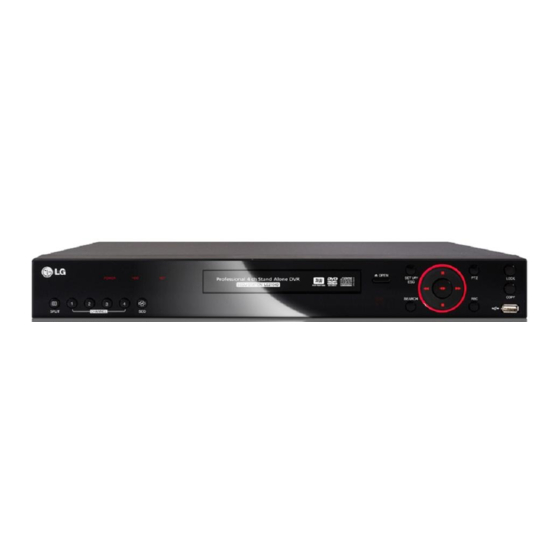
Page 8: Front Panel
Front Panel LE2104D model f g h LE2104 model f g h a POWER Indicator: Lights when the DVR is powered. f PTZ: Switches this unit to PTZ mode to control the PTZ camera connected. HDD Indicator: Blinks when the HDD is accessed. -
Page 9: Rear Panel
Rear Panel Rear panel with the TV or VGA output select switch. n o p Rear panel without the TV or VGA output select switch. n o p a VIDEO INPUT h ALARM IN/OUT Terminals Connect the camera’s video output to these BNC con- IN: Input terminals for alarm(relay) signal. -
Page 10: Remote Control
Remote Control • SPLIT: Press to see different multiscreen modes. • SEQ: Views the all channels in sequence on the full screen display mode. You cannot use sequence mode with the 4 split. • ALM.OFF: Cancels alarm activation and returns the sys- tem to the condition before the alarm was activated. -
Page 11: Connections And Settings
Connections and settings Precautions • Depending on the camera and other equipment there are various ways to connect the unit. Please refer to the camera manual or manuals for other devices as necessary for additional connection information. • Be sure to switch off the camera before installation and connection. Basic Connection Overview Connect the coaxial-type cameras Connect BNC type spot monitor. -
Page 12: Connecting Camera
The LE2104/LE2104D models without TV/VGA output select Connecting USB device switch can be outputted simultaneously from the VGA and MAIN OUT jack. On other LE2104/LE2104D models with TV/VGA output select switch, main monitor type should be selected to display the main screen. -
Page 13: Connecting Console (Rs-232C) Port
USB memory device LAN connection Insert the memory device into the USB port. The system Connect the LAN port to an available 10/100 base-T port automatically recognizes the device. with a straight ethernet cable (not supplied). The NET indi- cator on the front panel will be lit. Using a USB memory device the system software can be easily upgraded. -
Page 14: Connecting Alarm Input And Alarm Output
D1 or D2 port. It may cause a malfunction. • The MAIN and SPOT buttons of the LKD1000 controller are not activated for LE2104/LE2104D models. Alarm Output Connect the alarm device to the alarm output. Alarm signal output at an event occurrence. -
Page 15: Hdd Installation
The internal hard disk drive (HDD) is a fragile piece of equipment. Please follow the guidelines below when using You can install up to 2 HDDs. (LE2104 model only) the DVR to protect against possible HDD failure. However, since the product contains many parts which may... - Page 16 5. Attach the HDD onto the hard disk mounting brackets Note: with four screws. When you add the new HDD, do not change the position of the HDD. It may delete the current data and cause a mal- function. Replacing the Hard Disk Drive Turn the power of the unit off and detach the power plug from the outlet.
-
Page 17: System Operation
1. Turn on the unit. System booting will commence. The • If the DVR is turned off accidently and then turned on LG logo image will be displayed on the main monitor again, the DVR may take a long time to be rebooted. during the system booting. -
Page 18: General Explanation Of The Livescreen On The Main Monitor
General Explanation of the Live Displays the search menu. Screen on the Main Monitor Displays the PTZ remote control Main Monitor Screen window. Displays in the full screen display mode to return to the 4 division screen windows. Views the all channels in sequence on the full screen display mode. - Page 19 PTZ Camera Control To manually adjust the iris of a camera. You can control the cameras connected via the data port of RS-485 terminal. You must set the configuration between Displays the Selected the PTZ camera and the DVR. Preset Number 1.
- Page 20 2. Use number buttons to enter the memorized preset position’s index number then press ENTER or click the icon. The camera moves to the preset position and the picture of the camera in that position appears on the monitor. To Clear the Preset Position You can clear a memorized preset position.
- Page 21 Notes: Normal User Login (Local) • You can also use the COPY button on the front panel for Normal User Logout (Local) export function. Configuration Changed • Check the export device before you proceed. Configuration Imported Factory Default Set • You can export the recorded data only in the live mode.
-
Page 22: Confi Guration Menu
Confi guration menu Using a mouse to set a menu Use the left or right mouse buttons to set the menu. The features and options of the DVR are configured through the menu. The operations of this unit can be set via Button Function a menu displayed on the main monitor. -
Page 23: Camera Settings
• Covert: You can set the camera conditions to prevent operation by other users. If the covert option is set to ON, “LG logo” is displayed on the live window with POWER or NORMAL user. • Audio: You can connect the audio input with a specified camera input. - Page 24 Recording Settings for the PTZ cameras connected via the data port of Settings concerning normal recording. the RS-485 terminal. • Channel: Selects the desired channel to set the options. • Channel: Selects the desired channel to set the con- • Resolution: Selects the recording resolution.
- Page 25 Sensor Recording Motion Recording Settings concerning sensor recording. Settings concerning motion recording. • Channel: Selects the desired channel to set the options. • Channel: Selects the desired channel to set the options. • Resolution: Selects the recording resolution. • Resolution: Selects the recording resolution. •...
-
Page 26: Schedule Settings
Video Format 6. Select [OK] icon and press ENTER to confirm your set- tings. Selects the video format to NTSC or PAL according to your 7. Select [Exit] and press ENTER to exit the sub-setup video system format. menu. Note: This function is not activated for spot out channel. - Page 27 To Set the Recording Schedule for a Typical Green+Red (Continuous+Sensor event recording): Recording starts automatically from the preset time. Day of the Week When the sensor alarm occurs within a designated 1. Select a day of the week. time, change the continuous recording mode to The recording schedule screen is displayed.
- Page 28 3. Select a special day title on the list and press ENTER. The title color turns red. 4. Select the [Edit] icon then press ENTER to edit the spe- cial day or select the [Delete] icon to delete the special day schedule.
-
Page 29: Display Settings
Display settings Main Monitor • Dwell Time: You can set the channel sequence time to 2 SEC, 5 SEC, 10 SEC, 20 SEC, 30 SEC, 40 SEC, 50 SEC, 60 SEC, 70 SEC, 80 SEC or 90 SEC. Spot Monitor •... -
Page 30: Event Settings
Event Settings Motion • Channel: Select the channel to set motion detection. • Sensitivity: Set the level of sensitivity for the created motion detection area. Sensitivity can be set from level 01 to 10 or NONE. • Relay Output: ON: Outputs the alarm (relay) signal via the RELAY- OUT terminal. -
Page 31: Network Settings
5. Click the right mouse button to exit the settings. TCP/IP 6. Select [Exit] and press ENTER to exit the sub-setup menu. Output • DHCP: DHCP stands for Dynamic Host Configuration Protocol. ON: Network settings of this unit are configured automatically by the DHCP server. - Page 32 ON: Select to enable DDNS function. This free service is very useful when combined with the LG DDNS Server. It allows Internet users to con- When you want to change DDNS host name nect the LG DDNS Server using a Host Name, rather If you want to change the registered host name to new one, than an IP Address.
- Page 33 Notifi cation Mail • Sensor On: • Notification ON: Sends an e-mail when a sensor has occurred. ON: Notifies the user of unit operating information by e-mail according to notification settings. OFF: Not used. OFF: The notification function is not used. •...
-
Page 34: System Settings
Emergency System Settings • Notification: ON: Notifies the emergency agent about unit oper- ating information according to your notification settings. OFF: Notification function is not used. If you set to OFF, the Emergency ID, IP Address and Port options are not set. •... - Page 35 • Daylight Saving End: Select the Daylight Saving end Buzzer time. Caution: If you change the time setup, warning message will be dis- played. For example, if you delay the time by 10 minutes, the overlapped 10minutes data can be deleted. •...
- Page 36 User Update You can register a new user with various access rights to the The update feature allows you to upgrade DVR software DVR or client program. and add/upgrade PTZ protocols. In this case, the current DVR settings are not deleted or replaced during the update process.
- Page 37 Hard Disk Note: If you change the value of event partition, the current recorded data of HDD is deleted and the partition is reset. The partitions will be formatted automatically and the system will be restarted. Backup • Format: Initializes the HDD (Hard Disk Drive). All data on the selected HDD will be erased.
- Page 38 • You cannot use the [Estimate], [Start] and [Erase] • If you use the CD/DVD writer device for backup,the options in backup progressing. backup status will be displayed as shown below. • Do not remove the USB device while the backup is in - 1st.
- Page 39 System • IR Remote ID: Select the IR Remote ID for this unit (0~9). If you use multi systems set the IR Remote ID for each DVR unit. • DVR ID: Select the DVR ID for this unit (NONE, 1~16). If you use multi systems set the DVR ID for each DVR unit.
-
Page 40: Recording
Recording Images from a camera will be recorded on the built-in hard disk. Note: External recording devices can be used as copy areas for images recorded on the hard disk. It is impossible to record images on the external recording devices directly. Instant recording Ensure all the cameras are connected and that time and date have been set correctly. -
Page 41: Search And Playback
Search and Playback Playback It is possible to play a recorded image without stopping recording. 1. Select a channel you want to playback. 2. Press bB to play a recorded image of the previous 1 or 2 minutes of recording. The playback image will be displayed on the full screen window. - Page 42 10. Use v/V to select the channel you want to playback Event Search and press ENTER. Repeat this step to select the other Search a recorded picture by date and type of event. channels. 1. Use v/V to select the [Event Search] option then press 11.
- Page 43 Bookmark Search Functions available during playback Search the desired picture with a bookmark registered by Button the bookmark function. System Remote Front Function Control 1. Use v/V to select [Bookmark Search] then press ENTER. Control panel The bookmark list menu is displayed. Stop playback.
-
Page 44: Client Program
Connecting to the DVR Client program Register the Site Name Client Program is the network program of the LE2104 series You should register a site name to control DVR by the Client LG DVR. The description pictures may differ from your OS Program. -
Page 45: Main Screen Of Dvr Client Program
How to fi nd the IP Address • Up to 5 users can connect to the DVR system using the client program as shown below. In case of using the Static IP Address User User 1 User2 User3 User4 User5 Check the IP Address in the TCP/IP option of the DVR setup Case 1 Admin... -
Page 46: Live Mode
> Site Sequence: Each channel of the logged When the icon is clicked, the screen will be changed site in the sequence mode will be displayed to split mode and if the icon is clicked again, the in sequence. screen will be changed by sequence. Choose the display window mode. - Page 47 Note: 2. Select the PTZ camera channel window. Configuration of camera view is set the first time only. This 3. Use virtual remote control buttons to control the PTZ configuration setup is memorized for the next time and camera. displayed as it is. Using the live window You can play back the recorded data and monitor via net- work.
- Page 48 To Tour the Preset Positions To register preset posi- You can tour all preset positions. tions. 1. Click the icon. To move the camera to All registered preset positions in the camera will the preset position. be selected and the camera position image will be switched on to the active window.
-
Page 49: Search Mode
Search Mode You can search the data of a selected site name in the remote setup tab via the network. Using the Date/Time Search function Use to search a recorded picture by specifying date, hour and minute. 1. Select the event search tab. 2. -
Page 50: Remote Setup Mode
2. Set each option using the mouse (See page 24). up the convert option. The marked up channels are 3. Click the [OK] button to confirm the settings. displayed “LG logo” on the live windows for POWER or NORMAL user. Sensor Recording Settings 2. - Page 51 Schedule setup 2. Set each option using the mouse (see page 25). 1. Select a day of the week. 3. Click the [OK] button to confirm the settings. 2. Mark up the desired recording option. • No record: Do not schedule recording. Motion Recording Settings •...
-
Page 52: Network Setup
Schedule Copy Settings Event setup 1. Select the source day to copy. 2. Select the destination day from the day of the week, weekday or weekend options. 3. Click the copy button to copy the schedule data. Special day Settings 1. - Page 53 Mail Settings change the port number (1025 ~ 65535). You can set up to 9 IP address and port numbers. Set the mail options. • Notification: When you mark up the notification option, notify the user about unit operating information by E- System setup mail according to your notification settings.
-
Page 54: Remote Export Settings
Remote Export Settings Buzzer settings Select the buzzer options. • Button: Makes a sound when using the buttons. • Sensor: Makes a sound when an sensor occurs. You can copy the recorded images and audio data from the DVR unit to the PC. This function is permitted for •... - Page 55 • Delete: Delete the selected export setting schedule from the list. • Export: Click to start export the data of the selected export setting. • Cancel: Click it to cancel data exporting. • Exit: Click to exit the window. How to export the data 1.
-
Page 56: Additional Programs
(See page 33- 34). 1. Double-click the [LG Emergency Agent] icon to start the emergency agent program. The Emergency icon is displayed in the system tray on the bottom right of the screen. -
Page 57: Export Viewer Program
Message Search Export Viewer Program You can playback from the export data on the PC using this program. The export viewer program is saved automatically when you install the client program or export the data. Main Screen of Export Viewer 1. -
Page 58: Web Viewer Program
Playing Data Web Viewer Program 1. Double click the [Export Viewer] icon on the PC or run Logging in the Web Viewer the [Export Viewer.exe] file in the Export Viewer folder of the external USB device. If you insert the exported 1. - Page 59 Using the Web Viewer You can control the live image using the Web Viewer. Mode select icon. Click to change the PTZ View mode or Live View mode. Screen Mode selection icons. (See page 46) Live screen display win- dow (See page 18) Live screen control •...
-
Page 60: Reference
Check the power cable on the camera is connected correctly. played on the screen but the camera images are not Check there is no problem with the video cable connection from the camera to the LG displayed. DVR system. Turn off the DVR system and turn it on again. - Page 61 Symptoms Resolutions Check the audio recording option is correctly set for the camera you wish to record audio. Audio data recorded with video data is not playing. Check the speaker and audio (line input) on the rear of system are connected correctly. Check the connected speaker is working properly.
- Page 62 Symptoms Resolutions E-mail reception failed without SMTP server setting. • Make sure the network is correctly set. • Make sure the mail address is input correctly. • Check the spam mail setting of the inputted mail address. (If you set the spam mail, some mails are deleted automatically or classified in the spam mail box) •...
-
Page 63: Recommended Devices
Recommended Devices Supported USB Memory list Maker Model Name Capacity LG Electronics XTICK Mini Slide / Slide 1G/2G/4G IOCELL CellDisk Swing 1G/2G/4G/8G Sony MicroVault 1G/2G/4G S100 / M100 / V210W 1G/2G/4G SANDISK Cruzer Micro 512M/1G TRANSCEND 1G/2G IMATION Flash Drive Nano / Icon... -
Page 64: Time Zones
Time zones Timezone Timezone name Timezone Abbreviation Eniwetok, Kwajalein -12:00 Midway Island, Samoa -11:00 Hawaii -10:00 Alaska -09:00 -08:00 Pacific Time (US and Canada); Tajuana -08:00 -07:00 Mountain Time (US and Canada), Chihuahua, La Paz, -07:00 -06:00 Mazatlan, Arizona Central Time (US and Canada), Saskatchewan, Guadalajara, Mexico -06:00 -05:00 City, Monterrey, Central America... -
Page 65: Factory Default Confi Guration Settings
Factory Default Confi guration Settings Classification Detailed Items Default Setting 1st level 2nd level 3rd level Channel 01~04 Name CH 01~CH 04 Camera Covert Audio NONE, 01 ~ 04 Channel CH 01~CH 04 Port NONE Control ID Protocol LG_MULTIX Baud Rate 9600 Channel CH 01~CH 04... - Page 66 Classifi cation Detailed Items Default Setting 1st level 2nd level 3rd level Input Channel 01~04 Sensor Type N.O. Sensor Camera 01~04 Relay Output Event Channel 01~04 Motion Sensitivity Relay Output Output Relay Off ALARM ACK. DHCP IP Address NULL Subnet Mask NULL Gateway NULL...
- Page 67 Classifi cation Detailed Items Default Setting 1st level 2nd level 3rd level Date (2008.01.01) Time (None) Date Format (YYYY/MM/DD) Time Format 24 Hr (12 Hr) Date/Time Time Zone (GMT) Daylight Saving Daylight Saving Start Current Time Daylight Saving End Current Time Server PUBLIC SERVER Private Time Server...
-
Page 68: Recording Time Table (250Gb Hdd)
Recording Time Table (250GB HDD) NTSC Resolution Quality Recording Time (Hr) Recording Time (Hr) (NTSC/PAL) Video Video+Audio Video Video+Audio 1589 1090 1123 1895 1226 1187 1992 1266 12.5 1386 Lowest 2703 1520 2014 1275 2784 1545 2226 1356 3036 1620 2297 1383 3202... - Page 69 NTSC Resolution Quality Recording Time (Hr) Recording Time (Hr) (NTSC/PAL) Video Video+Audio Video Video+Audio 1160 12.5 1528 1061 1021 Lowest 1625 1107 1155 1790 1181 1258 2020 1277 1907 1231 12.5 1164 1186 1080 1414 1005 1213 1355 1233 12.5 704x240 Normal 704x288...
- Page 70 NTSC Resolution Quality Recording Time (Hr) Recording Time (Hr) (NTSC/PAL) Video Video+Audio Video Video+Audio Lowest 1093 1072 704x480 Normal 704x576 High Best Reference...
-
Page 71: Specifi Cations
User I/F User Interface Mouse, IR Remote, Keyboard Controller (LKD1000) Interface Type SATA Interanl HDD 1TB (Up to 2 HDDs) – LE2104 series Storage Max Capacity 500GB (Up to 1 HDD) – LE2104D series Internal ODD Yes (LE2104D model Only) Backup/Export Device Interface 3 x USB 2.0, Network... - Page 72 Network Connection Ethernet 10/100M, RJ-45 Bandwidth Control Network NTP (Network Time Protocol) Application SW PC Client, WEB Client, Emergency Agenct, Export Viewer Button Lock Covert Camera Protection Security User Level Management Data Integrity Check (Watermark) Multiplex Triplex Setup Configuration Export/Import USB Memory Stick, Network Daylight Saving System...
Need help?
Do you have a question about the LE2104 and is the answer not in the manual?
Questions and answers