Table of Contents
Advertisement
User Manual
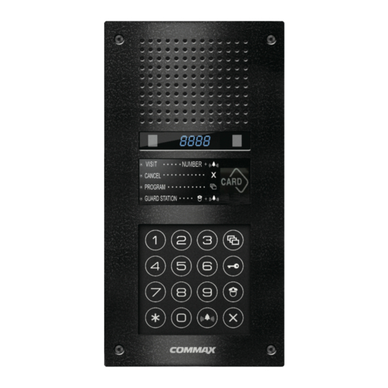
Anti Vandal lobby phone DRC-900LC/RF1
• Thank you for purchasing COMMAX products.
• Thank you for purchasing COMMAX products.
• Please carefully read this User's Guide (in particular, precautions for safety) before using a product and follow
• Please carefully read this User's Guide (in particular, precautions for safety) before using a product and follow
instructions to use a product exactly.
instructions to use a product exactly.
• The company is not responsible for any safety accidents caused by abnormal operation of the product.
• The company is not responsible for any safety accidents caused by abnormal operation of the product.
- Feature -
•Common 8 wires(When using the video phone)
•RF/ID
38
Advertisement
Table of Contents

Subscribe to Our Youtube Channel
Related Manuals for Commax DRC-900LC/RF1


Summary of Contents for Commax DRC-900LC/RF1
-
Page 1: User Manual
•Common 8 wires(When using the video phone) •RF/ID • Thank you for purchasing COMMAX products. • Thank you for purchasing COMMAX products. • Please carefully read this User’s Guide (in particular, precautions for safety) before using a product and follow •... -
Page 2: Table Of Contents
25. Miscellaneous ........................35 26. Part list ...........................35 27. Specifications ........................35 1. Greeting * Thank you for purchasing a COMMAX product * This product is a high tech Main Entrance interphone that supports electronic and remote keys features. Please read this manual carefully. -
Page 3: Safety Warning & Caution
2. Safety Warning & Caution Please follow the things described below in order to prevent any danger or property damage. Prohibition. Warning It may cause a serious damage or No disassembly injury if violated. No touch Must follow strictly. Caution Shows plugging out the power cord It may cause a minor damage or without an exception... - Page 4 Warning Please don’ t disassemble, If an abnormal sound, burning Please don’t insert any Please use only the designated repair or rebuild this product smell or smoke is coming out metallic or burnable materials batteries for the products of of the product, please plug out arbitrarily (please contact the into the ventilation hole.
-
Page 5: Overview
3. Overview 3-1. Part name Description Description Camera Electronic-key button Speaker Guard button FND Display Cancel button RF ID Call button Dial button Wiring connection terminal Microphone Reset switch Program button Switchgear connection terminal... - Page 6 3-2. Essentials ✽ Program Button ⑦ (P: Program ) This button is used to Program. Program : Program Enter ✽ Electronic Key Button (K : Key) ⑧ This button is used to release the door by using PIN. (Available only when the Electronic Key option has been set as OFF. When it is set as ON, Finger Print Recognition is enabled) ✽...
- Page 7 ✽ Change the message on FND To change the message on FND, press the Program button (P) for 5 seconds. 1) Displaying system version ⇨ 0101-9901 SLI DRC-900L Ver.1.1 2) Displaying general message ⇨ hELLo hAPPy dAy...
- Page 8 •Must know Before Use! This button is used to cancel the current operation. 1) Accessing All Features with the Program Button - When an error has been made as indicated by continuous beeps, please cancel and start again from the beginning. Beep- Beep-Beep Start again from the beginning (Error)
-
Page 9: Pin Types
4. PIN Types 4-1. Management PIN - This PIN is for use by the person in charge of the Management Office. - By default, this PIN is set as 4321. - For convenience, hereafter management PIN. 4-2. Building PIN - This is the common PIN for each main entrance. - By default, this PIN is set as 1234. -
Page 10: Setting Pin
5. Setting PIN. 5-1. Management PIN Setup - P - Old Management PIN – E – 0 – E - New PIN – E - Management PIN must be 4-digits long. - 0000 will no be recognized as a valid PIN. Enter the old PIN 4321. - Page 11 5-2. Building PIN Setup - P - Old Management PIN – E – 1 – E - New PIN – E - Building PIN must be 4-digits long. - 0000 will no be recognized as a valid PIN. 4 3 2 1 Enter the old PIN 4321.
- Page 12 5-3. Household PIN Setup - K – Program Number – E – Household Number – E – Old Household PIN – E – New PIN – P - Household PIN must be 4-digits long. - 0000, 1234 will no be recognized as a valid PIN. - This method of Household PIN change may vary depending on household interphone types.
-
Page 13: Household Pin Confirmation
6. Household PIN Confirmation 6-1. Household PIN Confirmation - P - Management PIN - E - Program Number - E – Household Number – E Press the Program button (P). Enter the Management PIN. Press the Call button (E). Press the Program Number(16). Household Number. -
Page 14: Configuring Building And Serial Numbers In The Main Entrance Interphone
7. Configuring Building and Serial Numbers in the Main Entrance Interphone P-Management PIN - E - 2 - E - Serial Number - E Enter the Management PIN. Press the Program button (P). Press the Call button (E). Press the Call button (E). The Serial Number previously Press the Program Number(2). - Page 15 7-2. Configuring Serial Number from the Main Entrance Interphone P – Management PIN - E - 3 - Serial Number – E Enter the Management PIN. Press the Program button (P). Press the Call button (E). Press the Call button (E) (The Serial Number previously Enter the new Serial Number.
-
Page 16: Using Remote Card Keys(Rf/Id)
8. Using Remote Cardkeys (RF/ID) 8-1. Testing Remote Cardkeys -P - Management PIN - E - 9 - E - Card Test - X (Cancel) -This feature is used to test Remote Cardkeys. Press the Press the Program button (P). Enter the Building (Management) PIN. - Page 17 8-2. Remote Cardkey Registration - P - Building Management PIN - E - 10 - E - Card Registration - X (Cancel) Press the Enter the Building (Management) PIN. Press the Program button (P). Call button (E). ex) Building PIN Press the Card Here Press the Press the...
- Page 18 8-3. Individual Deletion of Remote Cardkeys - P - Management PIN - E - 12 - E - Card Deletion - X (Cancel) Press the Enter the Building (Management) PIN. Press the Program button (P). Call button (E). ex) Building PIN Press the Card Here 1.
- Page 19 8-4. Confirming Remote Cardkey Registration - P - Building Management PIN - E - 13 - E - Card Confirmation - X (Cancel) Enter the Building (Management) PIN. Press the Press the Program button (P). ex) Building PIN Call button (E). Press the Press the Card Here Program Number (13).
- Page 20 8-5. All Remote Cardkey deletion - P - Building Management PIN - E - 11 - E - E - Refrain from deleting all Remote Cardkeys, except for during installation. Press the Enter the Building (Management) PIN. Press the Program button (P). Call button (E).
-
Page 21: Electronic Key Setting
9. Electronic key setting - P- Management PIN - E - 8 - E - 0 – E : Deactivate usage of electronic keys ( Available PIN number access) - P-Management PIN - E - 8 - E - E - : Deactivate usage of electronic keys Door ( Not available PIN access) - This feature is for deactivating or activating the use of electronic keys in door access . -
Page 22: Door Release Time Setup
10. Door Release Time Setup - P – Management PIN – E – 4 – E – Door Release Time - E - This feature asjusts the door release time. 4 3 2 1 Enter the Management PIN. Press the Program button (P). Press the Call button (E). -
Page 23: Line Call Setup
11. Line Call Setup - P-Management PIN - E - 21 - E - 0 - E : All calls - P-Management PIN - E - 21 - E – 0103 - E : Line call ex) This function is for calling to specified line like from 1sthouse line to 3rdhouse line. -
Page 24: Page Signal Selection
12. Page Signal Selection - P-Management PIN - E - 5 - E - 0 - E: Melody Tone - P-Management PIN - E - 5 - E - 1 - E: Bell (Ringer) - This feature sets the Recall tone heard when Households or the Guardhouse is paged from the Main Entrance. -
Page 25: The Number Of Emitting Chime Setup
13. The number of emitting chime setup - P-Management PIN - E - 7 - E - 0 - E: Constant call - P-Management PIN - E - 7 - E - 1 - E: Call once - This function is to set the call sound when make a call to household or guard station from the lobby. -
Page 26: Video Out Impedance Adjustment
14. Video Out Impedance Adjustment - P-Building (Management) PIN - E - 6 - E - 0 - E: Short Distance - P-Building (Management) PIN - E - 6 - E - 1 - E: Long Distance - By default, the unit is set for short distance. Do not change if possible. -
Page 27: Inputhousehold Number
15. InputHousehold number - P-Management PIN - E - 15 - E - Household Number - E-Multi Sub number - E - This function is for inputting household number with lobbyphone in case of a guard stationunit is not installed Enter the Management PIN. - Page 28 1. Press the Program button(P). (‘Prog’willappear) 2. Enter the Management PIN. 3. Press the Page button(E). 4. Enter number 15 (HouseholdInterphone Diagnosis). 5. Press the Page button (E). (‘idCh’ will appear) 6. Call to guard station from household 7. The Household’s status is shownon the displaywindow(FND). 8.
-
Page 29: A Talk Volume Control
16. A Talk volume control - P - Administration password - E - 28 - E - Volume(Level) - E - Through this function, You can adjust the speaker volume of the common lobby phone Press the Program button (P). Enter the Management PIN. -
Page 30: How To Set The Button Lighting
17. How to set the button linghting - P- Administration password - E - 27 - E - 0 - E : Light on (When it is touched) - P- Administration password - E - 27 - E - 1 - E : Light on (Always) - Through this function, you can adjust the light of the key button. -
Page 31: Paging The Household
18. Paging the Household Enter the Household Number Press the page button. Ex) unit 101 A paging tone will sound. Press the Call button (E). Wait for a reply. Start to conversation 19. Paging the Guard Station Press the Guard button. Press the Page button. -
Page 32: Door Release Using The Household Pin
20. Door Release Using the Household PIN * Household Number – K – Household PIN - E Press the Electronic key button. Enter the Household Number. Ex) To open the door of unit 101 Enter the Household PIN. Press the Page button. Press the Call button (E). -
Page 33: How To Use Lobby Phone
22. How to use lobby phone. * Calling to household from lobby phone * Household number – E Press the household number Press the Call button. Emit call sounds ex)In case of household 101 * Opening door with household PIN * Household number –... -
Page 34: Appendix (Various Program Summaries)
23. Appendix (Various Program Summaries) Various PIN Programs 1. P - Old Management PIN - E - 0 - E - New PIN- E: Management PIN Change 2. P- Old Management PIN -E -1 - E - New PIN - E: Building PIN Change 3. -
Page 35: Wiring Method
24. Wiring Method Lobby camera phone(DRC-900LC) -
Page 36: Miscellaneous
We will do our best to make you satisfy with our services. 26. Part list MANUAL 27. Specifications Installation Method Flush Mounted Model Name DRC-900LC/RF1 Transmission System Household (8 wire), Guard (4 wire) Rated Voltage , 0.5A Power Consumption Standby: 200mA, Max : 500mA Conversation... - Page 37 Memo...
- Page 38 513-11, Sangdaewon-dong, Jungwon-gu, Seongnam-si, Gyeonggi-do, Korea Int’l Business Dept. Tel. : +82-31-7393-540~550 Fax. : +82-31-745-2133 Web site : www.commax.com PM10900LCR10 Printed In Korea / 2014.01.104...
Need help?
Do you have a question about the DRC-900LC/RF1 and is the answer not in the manual?
Questions and answers